EP1321090A2 - Appareil électroménager, en particulier un lave-vaisselle, avec une porte ameliorée - Google Patents
Appareil électroménager, en particulier un lave-vaisselle, avec une porte ameliorée Download PDFInfo
- Publication number
- EP1321090A2 EP1321090A2 EP02024012A EP02024012A EP1321090A2 EP 1321090 A2 EP1321090 A2 EP 1321090A2 EP 02024012 A EP02024012 A EP 02024012A EP 02024012 A EP02024012 A EP 02024012A EP 1321090 A2 EP1321090 A2 EP 1321090A2
- Authority
- EP
- European Patent Office
- Prior art keywords
- electric
- home appliance
- door
- access door
- appliance according
- Prior art date
- Legal status (The legal status is an assumption and is not a legal conclusion. Google has not performed a legal analysis and makes no representation as to the accuracy of the status listed.)
- Withdrawn
Links
Images



Classifications
-
- A—HUMAN NECESSITIES
- A47—FURNITURE; DOMESTIC ARTICLES OR APPLIANCES; COFFEE MILLS; SPICE MILLS; SUCTION CLEANERS IN GENERAL
- A47L—DOMESTIC WASHING OR CLEANING; SUCTION CLEANERS IN GENERAL
- A47L15/00—Washing or rinsing machines for crockery or tableware
- A47L15/42—Details
- A47L15/4251—Details of the casing
- A47L15/4257—Details of the loading door
- A47L15/4259—Arrangements of locking or security/safety devices for doors, e.g. door latches, switch to stop operation when door is open
Definitions
- the present invention refers to an electric home appliance, in particular a dishwashing machine, provided with an improved door providing access to the interior of the machine.
- Household-type dishwashing machines are largely known to usually include, within an outer casing, a washing vessel that is open on the front and is capable of being closed, under interposition of a sealing gasket, by means of an access door that is hinged along an horizontal axis on the lower side thereof, so as this is described for instance in GB-A-2 166 790.
- Such an access door accommodates, usually in correspondence of a control box or panel appropriately provided on the upper side to this purpose, electronic and/or electromechanical control and setting devices which require respective wiring means for them to be duly connected with the circuitry arranged in the outer casing of the machine.
- control and setting devices can only be implemented in "special" dishwashing machines, i.e. dishwashing machines having a height of 91 cm, instead of the traditional standard height of 85 cm.
- dishwashing machines having a height of 91 cm, instead of the traditional standard height of 85 cm.
- an electric home appliance of the above cited kind which is substantially simple and low-cost, and is further provided with an access door in correspondence of which, albeit in the presence of standard dimensions, there are provided at least the four main control and setting devices, while at the same time clearing the same door from the need for any associated wiring to be provided there to electrically connect said devices with the remaining part of the machine.
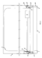
- the electric home appliance according to the present invention is preferably a dishwashing machine comprising an outer casing 1 with a worktop 2 on the upper side thereof, and sized to standard dimensions, with a height that may be of approx. 85 cm from the floor.
- the outer casing 1 contains a washing vessel 3 having an open front side that can be closed, under the interposition of a sealing gasket 15, by an access door 4 that is hinged on a horizontal axis 5 and is preferably, although not solely made of plastic material as a single-piece construction, in a substantially per sè known manner.
- the door 4 when it is in its closed position, extends to substantially cover the whole height and the whole width with respect to the front profile, i.e. contour of the machine.
- the dishwashing machine comprises setting and/or control devices that may be different in accordance with the various requirements and the different level of sophistication of the machine itself.
- said setting and/or control devices comprise at least a main power switch 6 ( Figures 2 and 3) to switch on and off, i.e. to energize and de-energize the machine, which is therefore connected to a circuitry (only shown schematically at 9) arranged in correspondence of the outer casing 1.
- the switch 6 (or any other similar electric device) is operable by the user through a push-button 7, or through any other equivalent mechanical interface device, which is mounted on the door 4 and is preferable accessible by the user in a convenient front position comprised within the overall contour of the same door. This enables the access door to be made to such a size and such a shape as to be capable of appropriately matching, i.e. adapting itself to the normal contour of standard kitchen cabinets installed in a juxtaposed arrangement.
- the interface push-button 7 is preferably capable of being accessed by the user in correspondence of the front surface of the door 4 or, possibly, of a control panel mounted on the same door.
- the interface device 7 may be provided for being accessed by the user in correspondence of a side surface of the door 4, such as for instance the top surface.
- the mechanical interface device 7 that is mounted on the door 4
- the power switch 6 is mounted on the outer casing 1 in such a manner as to be adapted to functionally couple with the same interface device only and solely when the door itself is substantially closed.
- the door 4 there is only mounted the mechanical portion 7 of the control means, whereas the electric portion 6 thereof is arranged on the outer casing 1 of the machine. This brings an important advantage with it.
- the door 4 can be made so as to include no electric wiring at all.
- the push-button 7 may be of the type loaded, i.e. biased by a spring 10 and associated to a bi-stable switching mechanism 11, so as illustrated in Figure 3.
- the push-button 7 comprises a pushing member 12 by means of which, when the door 4 is closed, it is capable of acting upon the switch 6, possibly under the interposition of a springy actuating rod 13 mounted in correspondence of the outer casing 1.
- the moving member of the power switch 6 is preferably arranged laterally with respect to the axis of the actuating rod 13, which is adapted to act upon the same switch through an inclined plane 14 that imparts an angular direction to the longitudinal displacement of the rod.
- the power switch 6 is preferably of the normally open type, so as to be able to make advantageously use of the mechanical disengagement thereof from the interface push-button 7 when the door 4 is opened.
- the switch 6 In this condition, in fact, regardless of the actual switching condition, i.e. on or off, of the push-button 7, the latter mechanically disengages the switch 6, which therefore changes over to its normally open position, thereby cutting off the general power supply to, i.e. de-energizing the machine.
- the switch 6 also acts as a safety provision adapted to automatically cut out the power supply to the appliance if the access door thereof is opened during operation.
- the electric home appliance may be provided with control means similar to said push-button 7 and comprising, in correspondence of the door 4, an interface push-button 8 of a monostable type that can be used for instance to select the various operational programmes, or duty cycles, of the machine.
- Said push-button 8 is preferably loaded, i.e. biased by a spring 16 and is provided with a pushing member 17 by means of which, only and solely when the door 4 is closed, it is capable of acting upon an electric contact 18, or the like, which is provided in correspondence of the outer casing 1 of the machine.
- said electric contact 18 may be mounted on an associated printed-circuit board 28, or the like, that includes an appropriate electronic driving circuit and is preferably arranged in correspondence of a front upper corner of the home appliance, in a position adjacent to the door 4.
- the pushing member 17 of the push-button 8 is capable of acting upon the electric contact 18 through a transmission member 19 that is mounted in correspondence of the outer casing 1 and is preferably shaped into a fork-like form, or the like, featuring a hinging point 20.
- this transmission member 19 enables a springy coupling to be provided between the interface push-button 8 and the electric contact 18, so as to enable assembly tolerances to be compensated for automatically when assembling the door 4 on to the outer casing 1, while at the same time preventing any excessive mechanical stress from being imparted to the electric portion 18, 28.
- the electric home appliance may also comprise control devices adapted to display indications concerning given operating conditions of the machine.
- these control devices comprise a user interface formed by an optical waveguide 21 that extends through the thickness, i.e. the cross-section of the door 4 and that, only when the same door is closed, establishes an optical coupling with at least a LED 22, or the like, so as to receive the light emitted by it and transmit such a light from the casing 1 through to the door 4 of the machine.
- Said LED 22 forms the electric portion of the control device and is provided in correspondence of the casing 1, as mounted for instance on a printed-circuit board 23 that also supports the power switch 6 and is preferably arranged in correspondence of a front upper corner of the appliance casing, in a position adjacent to the door 4.
- the LED 22 and the interface optical waveguide 21 can be coupled with each other, when the door 4 is closed, through the interposition of a further optical waveguide 24 mounted on the outer casing 1 of the appliance.
- Said optical waveguides 21 and 24 may be provided in the form of optical fibres; preferably. However, they are formed by simple transparent bars that are brought against each other axially and optically coupled with each other when the door 4 is closed, so as to be able of indicating for instance an power-on or power-off condition brought about by the actuation of the push-button 7.
- a similar solution can be provided in association with the push-button 8, with at least a LED 25, or the like, mounted on the printed-circuit board 28 in order to display in a coded manner (for instance, with different colours) an indication concerning the various operating programmes that are selected for the machine to carry out.
- an optical waveguide 26 mounted on the same door is coupled with the LED 25 through a further optical waveguide 27, that is provided adjacent thereto and aligned axially therewith on the outer casing 1 of the appliance, so as to be able to receive the light emitted by such a LED and transmit it from the casing 1 through to the door 4 of the appliance.
- the door 4 is most advantageously of the so-called "functional" type, i.e. of the type supporting all of the interfaces 7, 8, 21 and 26 of the setting and/or control devices of the appliance, and is at the same time cleared from the need to include wire harnesses to be provided in order to ensure an electric connection with the devices and circuits mounted in correspondence of the outer casing 1 of the appliance.
- the door 4 also offers the advantage of being able to be most quickly and conveniently removed and/or replaced with a similar door at any desired moment, for instance in view of adapting it to varying aesthetical requirements of the overall kitchen furniture.
- the mechanical and/or optical coupling thereof with the corresponding electric portions 6, 18, 22, 25 mounted on the casing 1 of the appliance may be implemented by means of respective angular transmissions of a mechanical and/or optical type, according to the particular case.
Landscapes
- Washing And Drying Of Tableware (AREA)
- Push-Button Switches (AREA)
- Detergent Compositions (AREA)
Applications Claiming Priority (2)
| Application Number | Priority Date | Filing Date | Title |
|---|---|---|---|
| ITPN20010089 ITPN20010089A1 (it) | 2001-12-19 | 2001-12-19 | Elettrodomestico, in particolare lavastoviglie, con porta di accesso perfezionata. |
| ITPN20010089 | 2001-12-19 |
Publications (2)
| Publication Number | Publication Date |
|---|---|
| EP1321090A2 true EP1321090A2 (fr) | 2003-06-25 |
| EP1321090A3 EP1321090A3 (fr) | 2004-12-22 |
Family
ID=11453315
Family Applications (1)
| Application Number | Title | Priority Date | Filing Date |
|---|---|---|---|
| EP02024012A Withdrawn EP1321090A3 (fr) | 2001-12-19 | 2002-10-26 | Appareil électroménager, en particulier un lave-vaisselle, avec une porte ameliorée |
Country Status (2)
| Country | Link |
|---|---|
| EP (1) | EP1321090A3 (fr) |
| IT (1) | ITPN20010089A1 (fr) |
Cited By (5)
| Publication number | Priority date | Publication date | Assignee | Title |
|---|---|---|---|---|
| WO2004056256A1 (fr) * | 2002-12-19 | 2004-07-08 | BSH Bosch und Siemens Hausgeräte GmbH | Appareil menager, en particulier appareil menager a encastrer |
| WO2006069832A1 (fr) * | 2004-12-27 | 2006-07-06 | BSH Bosch und Siemens Hausgeräte GmbH | Element indicateur de fonctionnement integre |
| WO2007065778A1 (fr) * | 2005-12-08 | 2007-06-14 | BSH Bosch und Siemens Hausgeräte GmbH | Lave-vaisselle avec porte amelioree |
| WO2008055819A1 (fr) * | 2006-11-07 | 2008-05-15 | BSH Bosch und Siemens Hausgeräte GmbH | Appareil ménager pour l'entretien du linge, notamment sèche-linge |
| DE102011087004B4 (de) | 2011-11-24 | 2025-02-20 | BSH Hausgeräte GmbH | Schalteranordnung für ein Haushaltsgerät |
Family Cites Families (7)
| Publication number | Priority date | Publication date | Assignee | Title |
|---|---|---|---|---|
| IT1270453B (it) * | 1993-02-15 | 1997-05-05 | Merloni Elettrodomestici Spa | Apparecchio frigorifero con un armadio e una porta,elementi di comandoe/o informazione incorporati nella porta e dispositivi elettrici nell'armadio |
| IT1289341B1 (it) * | 1996-12-17 | 1998-10-02 | Candy Spa | Dispositivo di impostazione di programmi di lavaggio per una macchina di lavaggio |
| IT1294116B1 (it) * | 1997-02-11 | 1999-03-22 | Electrolux Zanussi Elettrodome | Lavastoviglie domestica |
| DE19859973A1 (de) * | 1998-12-23 | 2000-06-29 | Bsh Bosch Siemens Hausgeraete | Haushaltgerät mit einer Tür und einem Bedienfeld |
| DE10022206C2 (de) * | 2000-05-06 | 2002-06-13 | Miele & Cie | Geschirrspülmaschine, insbesondere einbaufähige Geschirrspülmaschine mit einer optischen Betriebsanzeige |
| JP3941337B2 (ja) * | 2000-05-12 | 2007-07-04 | オムロン株式会社 | ドアスイッチ |
| TR200300992T1 (tr) * | 2001-02-13 | 2005-09-21 | Ar�El�K Anon�M ��Rket� | Ev cihazı. |
-
2001
- 2001-12-19 IT ITPN20010089 patent/ITPN20010089A1/it unknown
-
2002
- 2002-10-26 EP EP02024012A patent/EP1321090A3/fr not_active Withdrawn
Cited By (7)
| Publication number | Priority date | Publication date | Assignee | Title |
|---|---|---|---|---|
| WO2004056256A1 (fr) * | 2002-12-19 | 2004-07-08 | BSH Bosch und Siemens Hausgeräte GmbH | Appareil menager, en particulier appareil menager a encastrer |
| WO2006069832A1 (fr) * | 2004-12-27 | 2006-07-06 | BSH Bosch und Siemens Hausgeräte GmbH | Element indicateur de fonctionnement integre |
| US8810423B2 (en) | 2004-12-27 | 2014-08-19 | Bsh Bosch Und Siemens Hausgeraete Gmbh | Integrated operation display device |
| WO2007065778A1 (fr) * | 2005-12-08 | 2007-06-14 | BSH Bosch und Siemens Hausgeräte GmbH | Lave-vaisselle avec porte amelioree |
| WO2008055819A1 (fr) * | 2006-11-07 | 2008-05-15 | BSH Bosch und Siemens Hausgeräte GmbH | Appareil ménager pour l'entretien du linge, notamment sèche-linge |
| US8148653B2 (en) | 2006-11-07 | 2012-04-03 | Bsh Bosch Und Siemens Hausgeraete Gmbh | Domestic appliance for treating laundered articles, in particular tumble dryer |
| DE102011087004B4 (de) | 2011-11-24 | 2025-02-20 | BSH Hausgeräte GmbH | Schalteranordnung für ein Haushaltsgerät |
Also Published As
| Publication number | Publication date |
|---|---|
| ITPN20010089A1 (it) | 2003-06-19 |
| EP1321090A3 (fr) | 2004-12-22 |
Similar Documents
| Publication | Publication Date | Title |
|---|---|---|
| US7766525B2 (en) | Household appliance, particularly built-in household appliance | |
| KR101238770B1 (ko) | 냉장고 | |
| ES2316842T3 (es) | Indicador optico de funcionamiento para un aparato domestico, asi como un aparato domestico, particularmente aparato domestico empotrado. | |
| EP2355686B1 (fr) | Ensemble console pour un lave-vaisselle, et appareil associé | |
| US8810423B2 (en) | Integrated operation display device | |
| AU2004205205A1 (en) | Control panel assembly and method for controlling thereof | |
| RU2332622C2 (ru) | Холодильный аппарат | |
| US20060164397A1 (en) | Appliance with membrane overlay | |
| EP1332708A2 (fr) | Appareil domestique avec système d' éclairage | |
| EP0943283B1 (fr) | Module de commande pour appareil électroménager | |
| EP1829071A1 (fr) | Appareil menager | |
| MXPA05006546A (es) | Campana extractora y modulo de entrada. | |
| JPH05234446A (ja) | 電気スイッチ装置の付いたグリップバー及びフード | |
| EP0671143A1 (fr) | Machine à laver la vaisselle | |
| ITPN20010089A1 (it) | Elettrodomestico, in particolare lavastoviglie, con porta di accesso perfezionata. | |
| PT2116162E (pt) | Aparelho electrodoméstico de preparação culinária concebido para ser manipulado manualmente dotado com um elemento guia de cabo | |
| DE602005022025D1 (de) | Sicherheitsschloss für eine Tür eines Haushaltsgerätes | |
| JPH0614887B2 (ja) | 炊飯器 | |
| EP0331646A2 (fr) | Equipement de cuisine modulaire avec unité auxiliaire et dissimulée | |
| KR100690458B1 (ko) | 식기 세정기 | |
| KR20070002461A (ko) | 콘트롤 패널의 버튼 어셈블리 | |
| KR100593634B1 (ko) | 가전기기의 콘트롤패널조립체 | |
| KR20230075475A (ko) | 사용자 인터페이스를 갖는 가전 기기 | |
| CN216528552U (zh) | 按键组件和液体加热容器 | |
| CN218074665U (zh) | 料理机 |
Legal Events
| Date | Code | Title | Description |
|---|---|---|---|
| PUAI | Public reference made under article 153(3) epc to a published international application that has entered the european phase |
Free format text: ORIGINAL CODE: 0009012 |
|
| AK | Designated contracting states |
Designated state(s): AT BE BG CH CY CZ DE DK EE ES FI FR GB GR IE IT LI LU MC NL PT SE SK TR |
|
| AX | Request for extension of the european patent |
Extension state: AL LT LV MK RO SI |
|
| PUAL | Search report despatched |
Free format text: ORIGINAL CODE: 0009013 |
|
| AK | Designated contracting states |
Kind code of ref document: A3 Designated state(s): AT BE BG CH CY CZ DE DK EE ES FI FR GB GR IE IT LI LU MC NL PT SE SK TR |
|
| AX | Request for extension of the european patent |
Extension state: AL LT LV MK RO SI |
|
| AKX | Designation fees paid | ||
| REG | Reference to a national code |
Ref country code: DE Ref legal event code: 8566 |
|
| STAA | Information on the status of an ep patent application or granted ep patent |
Free format text: STATUS: THE APPLICATION IS DEEMED TO BE WITHDRAWN |
|
| 18D | Application deemed to be withdrawn |
Effective date: 20050623 |