EP1321334A2 - Rétroviseur extérieur avec caméra incorporée - Google Patents
Rétroviseur extérieur avec caméra incorporée Download PDFInfo
- Publication number
- EP1321334A2 EP1321334A2 EP02257850A EP02257850A EP1321334A2 EP 1321334 A2 EP1321334 A2 EP 1321334A2 EP 02257850 A EP02257850 A EP 02257850A EP 02257850 A EP02257850 A EP 02257850A EP 1321334 A2 EP1321334 A2 EP 1321334A2
- Authority
- EP
- European Patent Office
- Prior art keywords
- camera
- mirror
- mirror housing
- housing
- exterior rearview
- Prior art date
- Legal status (The legal status is an assumption and is not a legal conclusion. Google has not performed a legal analysis and makes no representation as to the accuracy of the status listed.)
- Withdrawn
Links
Images






Classifications
-
- B—PERFORMING OPERATIONS; TRANSPORTING
- B60—VEHICLES IN GENERAL
- B60R—VEHICLES, VEHICLE FITTINGS, OR VEHICLE PARTS, NOT OTHERWISE PROVIDED FOR
- B60R1/00—Optical viewing arrangements; Real-time viewing arrangements for drivers or passengers using optical image capturing systems, e.g. cameras or video systems specially adapted for use in or on vehicles
- B60R1/02—Rear-view mirror arrangements
- B60R1/06—Rear-view mirror arrangements mounted on vehicle exterior
-
- B—PERFORMING OPERATIONS; TRANSPORTING
- B60—VEHICLES IN GENERAL
- B60R—VEHICLES, VEHICLE FITTINGS, OR VEHICLE PARTS, NOT OTHERWISE PROVIDED FOR
- B60R11/00—Arrangements for holding or mounting articles, not otherwise provided for
- B60R11/04—Mounting of cameras operative during drive; Arrangement of controls thereof relative to the vehicle
-
- B—PERFORMING OPERATIONS; TRANSPORTING
- B60—VEHICLES IN GENERAL
- B60R—VEHICLES, VEHICLE FITTINGS, OR VEHICLE PARTS, NOT OTHERWISE PROVIDED FOR
- B60R1/00—Optical viewing arrangements; Real-time viewing arrangements for drivers or passengers using optical image capturing systems, e.g. cameras or video systems specially adapted for use in or on vehicles
- B60R1/02—Rear-view mirror arrangements
- B60R1/06—Rear-view mirror arrangements mounted on vehicle exterior
- B60R1/062—Rear-view mirror arrangements mounted on vehicle exterior with remote control for adjusting position
- B60R1/07—Rear-view mirror arrangements mounted on vehicle exterior with remote control for adjusting position by electrically powered actuators
- B60R1/074—Rear-view mirror arrangements mounted on vehicle exterior with remote control for adjusting position by electrically powered actuators for retracting the mirror arrangements to a non-use position alongside the vehicle
-
- B—PERFORMING OPERATIONS; TRANSPORTING
- B60—VEHICLES IN GENERAL
- B60R—VEHICLES, VEHICLE FITTINGS, OR VEHICLE PARTS, NOT OTHERWISE PROVIDED FOR
- B60R1/00—Optical viewing arrangements; Real-time viewing arrangements for drivers or passengers using optical image capturing systems, e.g. cameras or video systems specially adapted for use in or on vehicles
- B60R1/12—Mirror assemblies combined with other articles, e.g. clocks
-
- B—PERFORMING OPERATIONS; TRANSPORTING
- B60—VEHICLES IN GENERAL
- B60R—VEHICLES, VEHICLE FITTINGS, OR VEHICLE PARTS, NOT OTHERWISE PROVIDED FOR
- B60R1/00—Optical viewing arrangements; Real-time viewing arrangements for drivers or passengers using optical image capturing systems, e.g. cameras or video systems specially adapted for use in or on vehicles
- B60R1/12—Mirror assemblies combined with other articles, e.g. clocks
- B60R2001/1253—Mirror assemblies combined with other articles, e.g. clocks with cameras, video cameras or video screens
Definitions
- the present invention relates to a camera built-in exterior rearview mirror used for a side or door mirror of a vehicle, in which its mirror housing is pivotally driven for a position adjustment.
- An exterior mirror mounted on the front side of a vehicle such as an automobile, especially the one on a passenger-seat side, a door mirror for example, is likely to have a dead angle zone in an area right under the door mirror to the vicinity of a front wheel, thereby causing a poor field of view.
- a driver is likely to encounter an accident when an obstacle is caught under the wheel at starting of the vehicle if there exists one near the front wheel of passenger-seat side.
- Japan Laid-Open Patent 2000-16181 (hereinafter referred to as the prior art 1) discloses a door mirror having a small camera which is installed inside a mirror housing and oriented downward. Also as Japan Laid-Open Utility Model H03-42779 (hereinafter referred to as the prior art 2) discloses, an arrangement in which a small camera installed in a mirror housing is interlocked with shifting operation of a back gear has been known. Further, Japan Laid-Open Patent 2000-272418 (hereinafter referred to as the prior art 3) discloses an arrangement in which a small camera is installed rotationally controllable by a driving unit situated in a housing prepared outside a mirror housing.
- the door mirrors described in the prior arts improve a field of view with a small camera by capturing images of the front, side and rear as well as the lower portion of a vehicle and for example displaying them on a monitor disposed on an instrument panel in a vehicle cabin.
- the field of view especially with regard to the outer front alongside a vehicle can not be improved even if a wide angle or fish-eye lens is used since a lens of a small camera is oriented to the ground right under a mirror housing. Since the small camera is secured inside the mirror housing, the area of image captured by the camera varies inevitably when the mirror housing is retracted to a stored position on the side-door wall of a vehicle, pivoting in a rear direction from a normal use position (hereinafter referred to as neutral position). This means that a fixed image acquisition area, the same as that of the neutral position, can not be achieved when the mirror housing is pivoted front or rear of a vehicle.
- the camera built-in rearview mirrors described in the prior arts 2 and 3, in which a small camera capable of rotating with a rotational mechanism, can allow a lens of the small camera to keep approximately the same image acquisition area by rotationally controlling the camera while the mirror housing is retracted.
- the rearview mirrors shown in the prior arts 2 and 3 require troublesome handling associated with controlling of a movable portion for adjusting an image acquisition angle of the lens in order to keep an approximately the same image acquisition area, each time the mirror housing is retracted.
- the present invention presents a camera built-in exterior rearview mirror having a mirror housing which is mounted on a vehicle through a mirror base for free pivotal movement from a neutral position to a rear stored position and a front position, a camera module disposed in the mirror housing, a camera installed in the camera module and a camera angle adjusting means for adjusting an angle of the camera.
- the camera can restrain shifting of an image acquisition area so that it can be an approximately fixed area while the mirror housing makes a pivotal movement.
- the present invention based on the arrangement described above, which restrains the camera from shifting an image acquisition area depending on a pivotal movement of the mirror housing, does not have an affect on the image acquisition area and can keep an approximately fixed field of view which is the same as that of a neutral position, namely a normal use position.
- the present invention also provides a camera built-in exterior rearview mirror, in which the camera angle adjusting means has a camera control means for controlling rotationally the camera that is installed rotatably in the camera module.
- the present invention based on the aforementioned arrangement can control rotationally the camera in parallel with retracting of the mirror housing, thereby maintaining an approximately fixed image acquisition area so that its shifting depending on a pivotal movement of the mirror housing is restrained.
- the present invention still provides a camera built-in exterior rearview mirror, in which a lens of the camera installed in the camera module is oriented downward.
- the present invention can thus capture an image of the dead angle zone of a vehicle reliably. Also it allows the lens to be less likely to become soiled and improves an appearance of the exterior rearview mirror.
- the present invention yet provides a camera built-in exterior rearview mirror, in which the camera installed in the camera module captures images through a transparent element covering an observation opening made on the mirror housing.
- the present invention protects securely the lens of camera against being soiled, thereby maintaining high performance in terms of the image acquisition and the field of view.
- the present invention further provides a camera built-in exterior rearview mirror, in which the transparent element is integrally mounted to the camera module.
- the present invention thus enables covering of the observation opening with a transparent element in parallel while the camera module is installed in the mirror housing.
- the present invention still further provides a camera built-in exterior rearview mirror, in which a rotational axis of the camera installed rotatably in the camera module and a pivotal axis of the mirror housing are approximately parallel.
- the present invention based on the arrangement described above allows an easier adjustment of image acquisition area between the neutral position (normal use position) and the stored position.
- the present invention yet further provides a camera built-in exterior rearview mirror, in which a rotational angle of the camera is approximately the same as a pivotal angle of the mirror housing.
- the present invention in this way provides not only a rotational axis of the camera which is parallel to a pivotal axis of the mirror housing but also an easier adjustment of image acquisition area between the neutral (normal use) and stored positions.
- the present invention provides a camera built-in exterior rearview mirror, in which a pivotal movement of the mirror housing is controlled by a motor and the camera is also rotated by driving force of the motor.
- the present invention thus provides a driving motor, which is able not only to pivotally drive the mirror housing but also to serve as a rotational driving mechanism for the camera, allowing a reduction in the number of parts and easier wiring for a power supply unit.
- the present invention provides a camera built-in exterior rearview mirror, in which the camera module is installed in the mirror housing attachably thereto and detachably therefrom.
- the present invention thus enables easier mounting of the camera module into the mirror housing and easier wiring for the camera as well.
- the present invention according to a second aspect provides a camera built-in exterior rearview mirror having a mirror housing which is mounted on a vehicle through a mirror base for free pivotal movement from a neutral position to a rear stored position and a front position, a camera module disposed in the mirror housing, a camera installed in a camera housing of the camera module and a lens of the camera which is oriented downward so that the camera can be positioned to face somewhat diagonally outer front alongside the vehicle to capture a wide image.
- the camera is disposed rotatably about a rotational axis in the camera housing, which is approximately in parallel with a pivotal axis of the mirror housing.
- the rearview mirror includes a driving mechanism which rotates the camera to follow a pivotal movement of the mirror housing. The driving mechanism maintains an optical axis of the camera approximately in parallel relative to a pivotal displacement from a neutral position of the mirror housing so that shifting of an image acquisition area of the camera can be restrained.
- the present invention based on the arrangement described above allows the rotational axis of camera, which moves depending on pivotal movement of the mirror housing, to be in parallel with the pivotal axis thereof.
- the optical axis of camera is rotationally controlled while it keeps parallelism so that shifting of image acquisition area can be restrained.
- the camera built-in exterior rearview mirror according to the present invention can provide the approximately same image acquisition area as that of the neutral position even if the mirror housing makes a pivotal movement for retraction.
- the present invention also provides a camera built-in exterior rearview mirror, in which the drive mechanism includes an interlocking element which interlocks with a pivotal displacement of the mirror housing relative to the mirror base and rotates the camera not only in an opposite direction to a pivotal direction of the mirror housing but also by an rotational angle which is approximately the same as a pivotal angle of the mirror housing.
- the camera is rotated in an opposite direction of pivotal movement of the mirror housing and by the approximately same amount of rotational angle as that of the pivotal angle of mirror housing. In this way almost the same image acquisition area can be attained for both the neutral and stored positions of the mirror housing.
- the present invention according to a third aspect provides a camera built-in exterior rearview mirror having a mirror base secured to a vehicle, a support shaft projecting from the mirror base, a support frame supported rotatably on the mirror base through the support shaft, a mirror housing which is pivotable from a neutral position to a front position and a rear stored position relative to the mirror base, a camera housing installed in the mirror housing and a camera installed in the camera housing, which is secured to the mirror housing so that a lens of the camera can be oriented downward to face an observation opening provided on a bottom surface of the mirror housing.
- the camera is supported rotatably about a rotational axis, which is approximately in parallel with a pivotal axis, through a rotational shaft in the camera housing, and the lens is oriented so that an optical axis of the lens can be pointed to a somewhat diagonal outer front alongside the vehicle and the camera can capture a wide image.
- the rearview mirror includes a driving mechanism which can rotate the camera by a rotational angle which is approximately the same as a pivotal angle of the mirror housing in an opposite direction to a pivotal direction of the mirror housing.
- the optical axis can be controlled to keep parallelism continuously while the mirror housing makes a pivotal movement from the neutral position since the camera is rotated reversely by approximately the same amount of rotational angle as that of the pivotal angle of mirror housing.
- the image acquisition area can be kept approximately fixed even if the mirror housing makes a pivotal movement for retraction.
- the present invention also provides a camera built-in exterior rearview mirror having a first connection provided around the support shaft of mirror base, a second connection provided for the rotational shaft of camera and an interlocking element having a first holding element and a second holding element at both ends thereof, each of the first and second elements being in contact with each of the first and second connections, and the interlocking element supported shiftably and pivotably by a support frame to which the mirror housing is secured.
- the interlocking element can make a shifting and pivotal movement and rotate the rotational shaft of the camera interlocking with a pivotal movement of the mirror housing about the support shaft which supports the support frame.
- the present invention based on the arrangement described above provides a driving mechanism which can rotate the camera interlocked with a pivotal movement of the mirror housing, thereby allowing sharing of the driving mechanism which is prepared for pivotal drive control of the mirror housing and obviating another driving unit for rotational control of the camera.
- the present invention still provides a camera built-in exterior rearview mirror, in which at least the first connection includes a storing rib and a returning rib having a gap therebetween, a rod of the first holding element is disposed between the ribs, when the mirror housing is in the neutral position, the rod is placed apart from the storing rib, or when the mirror housing is in the stored position, the rod is placed apart from the returning rib.
- the present invention thus provides the storing and returning ribs having a gap therebetween on a connection for rotating the camera.
- a rod of the interlocking element lies between these ribs. Since when the mirror housing is in the neutral position, the rod is placed apart from storing rib and when it is in the stored position, the rod is placed apart from the returning rib, the rod of interlocking element comes into contact with the storing or returning rib after a commencement of pivotal movement at the neutral or stored position, respectively.
- a load for rotating the camera is imposed on the motor, thereby allowing a stable pivotal movement for the mirror housing.
- an electrically retractable rearview mirror which has a circuit for detecting an increase in the current of motor in a mechanism for terminating pivotal movement of mirror housing.
- the present invention yet provides a camera built-in exterior rearview mirror, in which the rod is released from the returning rib while the mirror housing makes a pivotal movement from the neutral position to the forward position.
- the movable area of rod can be set to be smaller since the rod is released from the returning rib while the mirror housing is on the way making a pivotal movement from the neutral to front position. In this way, downsizing of the driving mechanism for camera can be achieved and an unnecessary rotational movement of the camera can be prevented.
- the present invention further provides a camera built-in exterior rearview mirror, in which the mirror further includes an adjusting mechanism for restricting a rotational area for the camera contained in the camera housing.
- the adjusting mechanism positions the camera discretely for the neutral, stored and forward positions.
- the invention can thus improve the accuracy of positioning for the neutral, stored and front positions of the camera.
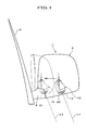
- FIG.1 is a front view showing the camera built-in exterior rearview mirror according to the first embodiment of the present invention, which is, for example, mounted to a vehicle as a door mirror and seen from the front of vehicle.
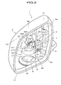
- FIG.2 is an enlarged perspective view showing the internal structure when a mirror is removed.
- FIG.3 is an enlarged sectional view showing the installation of camera in a mirror housing.
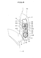
- FIG.4 is a plan view illustrating an outline of a camera position and movement of an optical axis of the mirror housing at neutral and stored positions in a pivotal movement of the mirror housing.
- FIG.5 is an enlarged sectional view illustrating an outline of a driving unit of camera at the neutral position in a pivotal movement of the mirror housing.
- a door mirror 1 of the present invention is mounted to a front door of passenger's seat side.
- This door mirror 1 is, as shown in FIG.2, accommodates a mirror (not shown), which is mounted in a plane of opening 2a located at the front of a mirror housing 2 made of synthetic resin.
- On the bottom surface of mirror housing 2 is made an observation opening as shown in FIG.3.
- a camera module 10 disposed in the mirror housing 2 faces this observation opening 3, which is covered by a transparent cover 4.
- mirror housing 2 is secured to a support frame 5, which is supported rotatably in a horizontal direction about a support shaft 7 projecting from a mirror base 6 to be secured to a door of vehicle W.
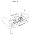
- the mirror housing 2 is thus mounted pivotably on the mirror base 6, from a neutral position N1 to a rearward stored position N2 or to a forward position N3, as shown in FIGS.4 - 7.
- the support frame 5 may be integrally molded with the mirror housing 2.
- the camera module 10 comprises a camera housing 11 and a camera 12 installed in the camera housing 11.
- the camera 12 is disposed so that a lens 13 is oriented downward to face the observation opening 3 of mirror housing 2. Further, the lens 13 of camera 12 is disposed so that an optical axis L1 is pointed to a somewhat diagonal outer front alongside the vehicle W to capture wide images.
- the camera module 10 When the camera module 10 is installed into the mirror housing 2, it is mounted to the support frame 5 attachably thereto and detachably therefrom by fixing with screws, for example, inserted through the observation opening 3 made on the bottom surface of mirror housing 2.
- the camera module 10, to which the transparent cover 4 is mounted in advance may be installed in the mirror housing 2 so that the observation opening 3 can be covered by the transparent cover 4 simultaneously.
- the camera 12 is supported rotatably about a rotational axis O2 of a rotational shaft 14 in the camera housing 11, which is parallel to a rotational axis O1 of mirror housing 2. As shown in FIG.3, an end of the rotational shaft 14 penetrates through a watertight seal 15 to the outside of camera housing 11.
- the camera 12 rotates interlocking with a pivotal movement of mirror housing 2 driven by a motor (not shown), in a Y direction shown with a solid arrow in FIG.4, for example.
- the associated rotational angle of camera 12 is approximately the same as the pivotal angle of mirror housing 2 and the direction is opposite to that of mirror housing 2.
- optical axes L1 and L2 defined at a neutral position N1 and a stored position N2 respectively can keep approximate parallelism while the mirror housing 2 makes a pivotal movement from N1 to N2, so that shifting of image acquisition area can be restrained except for that caused by the rotational error of camera 12.
- the camera 12 can keep an approximately fixed image acquisition area not depending on a pivotal movement of mirror housing 2.
- a driving mechanism 20 comprises a first connecting element 21 provided around the support shaft 7 of mirror base 6, a second connecting element 22 provided on a top of the rotational shaft 14 of camera 12 projecting from a frame 11A formed on a top of the camera housing 11, an interlocking element 23 for interlocking the first and second connecting elements 21 and 22 and rods 24 and 25 serving as a first and second holding elements provided on both ends of the interlocking element 23, respectively.
- the first and second rods 24 and 25, which are welded to both ends of the interlocking element 23 respectively, project therefrom.
- the first connecting element 21 comprises a retracting rib 21A and a returning rib 21B which are disposed apart from each other.
- the second connecting element 22 has the same type of ribs, a retracting rib 22A and a returning rib 22B.
- the first rod 24 lies between the retracting rib 21A and returning rib 21B around the first connecting element 21.
- the second rod 25 lies between the retracting rib 22A and returning rib 22B around the second connecting element 22.
- the first rod 24 comes in contact with the retracting rib 21A with a delay after the mirror housing 2 starts making a pivotal movement from the neutral position N1 to the stored position N2.
- the first rod 24 comes in contact with the returning rib 21B with a delay after the mirror housing 2 starts making a pivotal movement from the stored position N2 to the neutral position N1.
- the camera 12 thus rotates with some error relative to the pivotal movement of mirror housing 2.
- the height of retracting rib 21A is arranged to be larger than that of the returning rib 21B for the first connecting element 21 provided around the support shaft 7 of mirror base 6.
- the first trod 24 can be released from the returning rib 21B while the mirror housing 2 makes a pivotal movement from the neutral position N1 shown in FIG.5 to the front position N3 shown in FIG.7. It will thus protect the camera 12 against an excessive rotation by limiting the action of first rod 24.
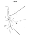
- FIG.8 shows an image acquisition area captured by the camera 12 at the neutral position N1 and the stored position N2 of door mirror 1 according to the present invention resulting from a pivotal movement of the mirror housing 2, compared with that of a conventional door mirror at a stored position.
- FIG.8 when the mirror housing 2 is in the neutral position N1, an image can be captured covering the neutral position N1 to the stored position N2 evenly as shown by solid line P in FIG.8.
- the vicinity of the front wheel of passenger's seat side of vehicle W is displayed on a monitor (not shown) disposed on the driver's seat side inside the cabin.
- the mirror housing 2 makes a pivotal movement from the neutral position N1 to the stored position N2, an image acquisition area by the camera 12 conventionally shifts greatly as shown by two-dot chain line Q in FIG.8.
- the optical axis L1 of lens 13 is oriented to a somewhat diagonal outer front alongside the vehicle W when the mirror housing 2 is in the neutral position N1.
- the location of optical axis L1 shifts from a point A1 to a point A2 according as the mirror housing 2 makes a pivotal movement from the neutral position N1 to the stored position N2.
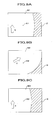
- a point B1 located at the center of uppermost portion of the monitor displaying a captured image E for the vicinity of front wheel of vehicle W shown in FIG.9A, also shifts to a point B2 shown in FIG.9B when the mirror housing 2 makes a pivotal movement to the stored position N2.
- the image acquisition area captured by camera 12 thus varies, so that the camera 12 fails to capture the image for the vicinity of the front wheel of vehicle W at the stored position N2 since the camera is adjusted for the neutral position N1.
- a traveling direction of the vehicle W also varies, it is likely to bring about confusion of a driver due to misapprehension.
- the camera 12 is mounted rotatably to the inside of mirror housing 2, and the pivotal axis O1 of mirror housing 2 and the rotational axis O2 of camera 12 are configured to be parallel.
- the camera 12 is controlled to rotate reversely relative to the mirror housing 2 by the rotational angle which is approximately the same as the pivotal angle of mirror housing 2.
- the point A1 which is representative of the location of optical axis L1 of camera 12 when the mirror housing 2 is in the neutral position N1 as shown in FIG.8, shifts to a point A3 for the stored position N2.
- the point B1 located at the center of uppermost portion of the monitor also shifts to a point B3 shown in FIG.9C for the stored position N2.
- the optical axis L1 of neutral position N1 and the optical axis L2 of stored position N2 keep approximate parallelism therebetween so that shifting of the image acquisition area can be restrained for a pivotal displacement of mirror housing 2 from the neutral position N1, as shown in FIGS.1 and 4.
- the image area captured by the camera 12 at the stored position N2 thereby approximately the same as that at the neutral position N1 when the mirror housing 2 is stored.
- the image acquisition area captured by the camera 12 at the stored position N2 is only slightly different from that of normal use at the neutral position N1 (shown by the solid line P) as shown by the dotted line R, thus permitting acquisition of images for approximately the same area, the vicinity of the front wheel of vehicle W.
- the camera built-in exterior rearview mirror of the present invention includes the driving mechanism 20, which serves as a camera angle adjuster for the camera 12 so that it can adjust an angle of the camera 12 depending on the movement of mirror housing 2 that is mounted pivotably to the vehicle W from the neutral position N1 to the rear stored position N2, as shown in FIGS. 4 and 6.
- the driving mechanism 20 restrains shifting of the image acquisition area and provides an approximately fixed one for the camera 12 while the mirror housing 2 makes a pivotal movement. Therefore, retracting of the mirror housing 2 to the stored position does not affect the image acquisition area of camera.
- a camera control means is provided for the camera 12 for controlling a camera angle adjuster, rotational control of the camera 12 can be performed simultaneously with retracting operation of the mirror housing 2. This restrains shifting of the image acquisition area and provides an approximately fixed one for a pivotal movement of the mirror housing 2.
- the camera 12 mounted in the camera housing 11 of camera module 10 is arranged so that the lens 13 is oriented downward and camera 12 capture images through the transparent cover 4 covering the observation opening 3 of mirror housing 2.
- the camera 12 can thus reliably capture images of the vicinity of the front wheel of vehicle W, particularly the dead angle zone of passenger's seat side. Further, this arrangement not only prevents the lens of camera 12 from being soiled but also improves appearance required for an exterior rearview mirror.
- the rotational axis O2 of rotational shaft 14 of camera 12 is positioned in parallel with the pivotal axis O1 of mirror housing 2, which is supported pivotably by the support shaft 7 of mirror base 6 through the support frame 5.
- the camera 12 is thereby controlled so that the rotational angle is approximately the same as the pivotal angle of mirror housing 2 and the direction is opposite to the pivotal direction Y thereof. It helps adjust the image acquisition area for the camera 12 between the neutral (normal use) position N1 and the stored position N2 of mirror housing 2 easily.
- this driving motor can simultaneously serve as a rotational driving mechanism for the camera 12. In this way another dedicated rotational driving mechanism is not required for rotational control of the camera 12, thereby allowing both a reduction in the cost by saving of parts and easier wiring of a power supply unit.
- the camera module 10 comprises the camera housing 11 and the camera 12 rotatably mounted therein, mounting of the camera module 10 in the mirror housing 2 and wiring for the camera 12 can be more easily done.
- FIG.10 shows a camera driving mechanism of a second embodiment for the door mirror according to the present invention.
- a driving mechanism 30 of the second embodiment employs a rod arm 31 in place of the interlocking element of the first embodiment described before.
- One end of the rod arm 31 serves as a first holding element 32, and the other end, which branches off in two parts ⁇ a retracting arm 33A and a returning arm 33B, serving as a second holding element 33.
- the rod arm 31 is supported through an axis 34 shiftably and pivotably by a support frame 5 which supports a mirror housing 2.
- a first connection 35 made of a projection is provided on a periphery of a support shaft 7 on a mirror base 6.
- a second connection 36 comprises a lever 36A, one end of which is fixed rotatably to a top of a rotation shaft 14 of a camera 12, and a pin 36B provided on the other end of the lever 36A.
- the first holding element 32 of rod arm 31 is in contact with the first connection 35.
- the pin 36B of second connection 36 lies between the retracting and returning arms 33A and 33B, serving as the second holding element 33.
- the camera 12 is controlled so that the rotational angle thereof can be approximately the same as the pivotal angle of mirror housing 2 and the rotational direction is opposite to that of mirror housing 2 while the mirror housing 2 makes a pivotal movement (e.g. Y direction of retracting shown by the solid line in FIG.10).
- the first holding element 32 comes into contact with a stopper 37, thereby rotating the camera 12.
- FIG.11A is a figure showing a camera driving mechanism of a third embodiment for the door mirror according to the present invention.
- FIGS.11B and 11C are similar figures for a fourth and a fifth embodiments, respectively.
- a driving mechanism 40 of the third embodiment comprises a link 41 and a rotational frame 42 which is an upper portion of a camera housing 11 and can rotate horizontally.
- link 41 is supported around a connecting shaft 7 through an axis on a mirror base 6 and the other end is supported around the rotational frame 42 through another axis.
- An upper portion of a camera 12 is secured to the rotational frame 42 so that a rotational axis 02 of camera 12 is aligned with another rotational axis of rotational frame 42.
- the camera 12 is in this way controlled so that the rotational angle thereof is approximately the same as the pivotal angle of mirror housing 2 and the rotational direction is opposite to that of mirror housing 2 while the mirror housing 2 makes a pivotal movement (e.g. Y direction of retracting shown by the solid line in FIG.11A).
- a driving mechanism 50 of the fourth embodiment comprises a first gear 51 machined around a support shaft 7 on a mirror base 6. Also the driving mechanism 50 has a second gear 53 machined around a rotational frame 52 of a camera housing 11 supporting a camera 12 and a timing belt 54 connecting the first and second gears 51 and 53.
- the camera 12 is in this way controlled so that the rotational angle thereof is approximately the same as the pivotal angle of mirror housing 2 and the rotational direction is opposite to that of mirror housing 2 while the mirror housing 2 makes a pivotal movement (e.g. Y direction of retracting shown by the solid line in FIG.11B).
- a driving mechanism 60 of the fifth embodiment comprises a first gear 61 machined around a support shaft 7 on a mirror base 6. Also the driving mechanism 60 has a second gear 63 machined around a rotational frame 62 supporting a camera 12 and a gear 64 engaging with the first and second gears 61 and 63 therebetween.
- the camera 12 is in this way controlled so that the rotational angle thereof is approximately the same as the pivotal angle of mirror housing 2 and the rotational direction is opposite to that of mirror housing 2 while the mirror housing 2 makes a pivotal movement (e.g. Y direction of retracting shown by the solid line in FIG.11C).
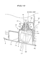
- the camera module 10 has an adjusting mechanism 70 which positions the camera 12 rotationally, which is rotatably supported in the camera housing 11, at the neutral position N1, stored position N2 and forward position N3 discretely.
- the adjusting mechanism 70 is mounted in a frame 11A connected to an upper portion of the camera housing 11, as shown in FIG.12. Inside the frame 11A, a middle frame 71 and a case 72 installed thereon define a storing space S for the adjusting mechanism 70.
- the rotational shaft 14 of camera 12 is inserted through an axial hole 71a made on the middle frame 71 and one end of the rotational shaft 14 penetrates a top of the frame 11A of camera housing 11.
- the second connecting element 22, with which the second rod 25 serving as the second holding element comes into contact, is provided for the exposed portion of rotational shaft 14 and thereby the rotational shaft 14 rotates through the driving mechanism 20 following a pivotal movement of the mirror housing 2.
- a plate clutch 74 which has an axial hole 74a for inserting the rotational shaft 14, is mated therewith.
- There are three pieces of depressions 75 on the inner circumference of axial hole 74a at regular intervals with the angle ⁇ ( ⁇ 120 deg.), which are correlated with the projections 73, respectively.
- Each depression 75 can engage with each projection 73.
- the plate clutch 74 rotates synchronized with the rotational shaft 14.
- grooves 76A, grooves 76B and grooves 76C each of which has a cross section of V shape extending in a radial direction.
- a groove 78 for insertion of a V plate 79 is formed around the rotational shaft 14 so that the groove 78 is located above the plate clutch 74 while it is mated with the rotational shaft 14.
- the V plate 79 is fixed by the groove 78 attachably thereto and detachably therefrom.
- the V plate 79 is for restraining a washer 80, which is mated with the rotational shaft 14, from displacing upward.
- a coil spring 81 is interposed between the washer 80 and the plate clutch 74.
- the urging force of coil spring 81 urges the plate clutch 74 toward the middle frame 71 of camera housing 11 so that the grooves 76A, 76B and 76C can be engaged elastically with the projections 77 at the neutral position N1, stored position N2 and forward position N3.
- the plate clutch 74 is thus allowed to rotate discretely synchronized with the rotation of rotational shaft 14 of camera 12, which is driven by a pivotal movement of the mirror housing 2.
- the grooves 76A can position the neutral position N1, the grooves 76B the stored position N2 and the grooves 76C the forward position N3, respectively. In this way the accuracy of positioning of camera 12 at the neutral, stored and forward positions N1, N2 and N3 during a pivotal movement of the mirror housing 2 can be improved.
- the aforementioned adjusting mechanism 70 regulates the rotation of camera 12 so that the hatched projections 77 shown in FIG.14 engage with the grooves 76C, for example, for positioning of the forward position N3. If the mirror housing 2 makes a further pivotal movement beyond the forward position N3 after the rod 24 of driving mechanism 20 is released from the returning rib 21B, the adjusting mechanism 70 prevents the further rotation of camera 12, thereby restraining shifting of an image acquisition area. It also allows a smooth rotational movement of the camera 12 when the mirror housing 2 makes a return pivotal movement from the forward position N3 back to the neutral position N1.
- the major object of the present invention is to restrain shifting of the image acquisition area captured by camera 12 as much as possible when the mirror housing 2 is stored, even if an exactly fixed image acquisition area can not be maintained.
- the present invention which has been described in the above embodiments referring to a door mirror as an example of the exterior rearview mirror, can be applied to a side mirror.
Landscapes
- Engineering & Computer Science (AREA)
- Mechanical Engineering (AREA)
- Multimedia (AREA)
- Rear-View Mirror Devices That Are Mounted On The Exterior Of The Vehicle (AREA)
- Studio Devices (AREA)
- Fittings On The Vehicle Exterior For Carrying Loads, And Devices For Holding Or Mounting Articles (AREA)
Applications Claiming Priority (2)
| Application Number | Priority Date | Filing Date | Title |
|---|---|---|---|
| JP2001369148A JP3854499B2 (ja) | 2001-12-03 | 2001-12-03 | カメラ内蔵型アウター用バックミラー |
| JP2001369148 | 2001-12-03 |
Publications (2)
| Publication Number | Publication Date |
|---|---|
| EP1321334A2 true EP1321334A2 (fr) | 2003-06-25 |
| EP1321334A3 EP1321334A3 (fr) | 2004-02-04 |
Family
ID=19178599
Family Applications (1)
| Application Number | Title | Priority Date | Filing Date |
|---|---|---|---|
| EP02257850A Withdrawn EP1321334A3 (fr) | 2001-12-03 | 2002-11-14 | Rétroviseur extérieur avec caméra incorporée |
Country Status (5)
| Country | Link |
|---|---|
| US (1) | US20030103142A1 (fr) |
| EP (1) | EP1321334A3 (fr) |
| JP (1) | JP3854499B2 (fr) |
| KR (1) | KR100491023B1 (fr) |
| CN (1) | CN1314554C (fr) |
Cited By (9)
| Publication number | Priority date | Publication date | Assignee | Title |
|---|---|---|---|---|
| EP1465428A1 (fr) * | 2003-04-02 | 2004-10-06 | Toyota Jidosha Kabushiki Kaisha | Appareil d'affichage d'image et procédé d'affichage d'image pour véhicule |
| EP1500558A4 (fr) * | 2002-04-26 | 2005-05-04 | Sony Corp | Dispositif de retroviseur exterieur de vehicule |
| US7040772B2 (en) | 2001-06-15 | 2006-05-09 | Russell Keith Ambrose | Vehicle mirror |
| EP2163431A1 (fr) * | 2008-09-16 | 2010-03-17 | Honda Motor Co., Ltd | Appareil de surveillance de l'environnement du véhicule |
| DE102009031809A1 (de) * | 2009-07-03 | 2011-01-13 | Volkswagen Ag | Verfahren und Vorrichtung zur Vermessung des Umfeldes eines Kraftfahrzeugs |
| EP1987986A3 (fr) * | 2007-05-03 | 2011-03-30 | Delphi Technologies, Inc. | Haut-parleur externe de véhicule et système de communication |
| DE102011078230A1 (de) * | 2011-06-28 | 2013-01-03 | Kuhnke Automotive Gmbh & Co. Kg | Verschwenken eines Objekts, insbesondere einer Fahrzeugkamera |
| EP3281825A1 (fr) * | 2016-08-10 | 2018-02-14 | Continental Automotive GmbH | Unité de rétroviseur |
| EP4397544A1 (fr) * | 2023-01-09 | 2024-07-10 | Volvo Car Corporation | Ensemble rétroviseur pour véhicule et véhicule |
Families Citing this family (159)
| Publication number | Priority date | Publication date | Assignee | Title |
|---|---|---|---|---|
| US6822563B2 (en) | 1997-09-22 | 2004-11-23 | Donnelly Corporation | Vehicle imaging system with accessory control |
| US5910854A (en) | 1993-02-26 | 1999-06-08 | Donnelly Corporation | Electrochromic polymeric solid films, manufacturing electrochromic devices using such solid films, and processes for making such solid films and devices |
| US5877897A (en) | 1993-02-26 | 1999-03-02 | Donnelly Corporation | Automatic rearview mirror, vehicle lighting control and vehicle interior monitoring system using a photosensor array |
| US5668663A (en) | 1994-05-05 | 1997-09-16 | Donnelly Corporation | Electrochromic mirrors and devices |
| US6891563B2 (en) | 1996-05-22 | 2005-05-10 | Donnelly Corporation | Vehicular vision system |
| US7655894B2 (en) | 1996-03-25 | 2010-02-02 | Donnelly Corporation | Vehicular image sensing system |
| US6326613B1 (en) | 1998-01-07 | 2001-12-04 | Donnelly Corporation | Vehicle interior mirror assembly adapted for containing a rain sensor |
| US8294975B2 (en) | 1997-08-25 | 2012-10-23 | Donnelly Corporation | Automotive rearview mirror assembly |
| US6172613B1 (en) | 1998-02-18 | 2001-01-09 | Donnelly Corporation | Rearview mirror assembly incorporating vehicle information display |
| US6124886A (en) | 1997-08-25 | 2000-09-26 | Donnelly Corporation | Modular rearview mirror assembly |
| US8288711B2 (en) | 1998-01-07 | 2012-10-16 | Donnelly Corporation | Interior rearview mirror system with forwardly-viewing camera and a control |
| US6445287B1 (en) | 2000-02-28 | 2002-09-03 | Donnelly Corporation | Tire inflation assistance monitoring system |
| US6329925B1 (en) | 1999-11-24 | 2001-12-11 | Donnelly Corporation | Rearview mirror assembly with added feature modular display |
| US6693517B2 (en) | 2000-04-21 | 2004-02-17 | Donnelly Corporation | Vehicle mirror assembly communicating wirelessly with vehicle accessories and occupants |
| US6477464B2 (en) | 2000-03-09 | 2002-11-05 | Donnelly Corporation | Complete mirror-based global-positioning system (GPS) navigation solution |
| US7195381B2 (en) | 2001-01-23 | 2007-03-27 | Donnelly Corporation | Vehicle interior LED lighting system |
| US7167796B2 (en) | 2000-03-09 | 2007-01-23 | Donnelly Corporation | Vehicle navigation system for use with a telematics system |
| US7370983B2 (en) | 2000-03-02 | 2008-05-13 | Donnelly Corporation | Interior mirror assembly with display |
| WO2001064481A2 (fr) | 2000-03-02 | 2001-09-07 | Donnelly Corporation | Systeme de miroir video integrant un module accessoire |
| US7255451B2 (en) | 2002-09-20 | 2007-08-14 | Donnelly Corporation | Electro-optic mirror cell |
| US7581859B2 (en) | 2005-09-14 | 2009-09-01 | Donnelly Corp. | Display device for exterior rearview mirror |
| US7697027B2 (en) | 2001-07-31 | 2010-04-13 | Donnelly Corporation | Vehicular video system |
| AU2003225228A1 (en) | 2002-05-03 | 2003-11-17 | Donnelly Corporation | Object detection system for vehicle |
| US6918674B2 (en) | 2002-05-03 | 2005-07-19 | Donnelly Corporation | Vehicle rearview mirror system |
| JP4088100B2 (ja) * | 2002-05-14 | 2008-05-21 | 株式会社村上開明堂 | カメラ内蔵型バックミラー装置 |
| WO2003105099A1 (fr) | 2002-06-06 | 2003-12-18 | Donnelly Corporation | Systeme de miroir de courtoisie interieur a boussole |
| US7329013B2 (en) | 2002-06-06 | 2008-02-12 | Donnelly Corporation | Interior rearview mirror system with compass |
| US7274501B2 (en) | 2002-09-20 | 2007-09-25 | Donnelly Corporation | Mirror reflective element assembly |
| US7310177B2 (en) | 2002-09-20 | 2007-12-18 | Donnelly Corporation | Electro-optic reflective element assembly |
| US20040218041A1 (en) * | 2003-01-30 | 2004-11-04 | Ichikoh Industries, Ltd. | Outside mirror for vehicle |
| US7289037B2 (en) | 2003-05-19 | 2007-10-30 | Donnelly Corporation | Mirror assembly for vehicle |
| WO2004104626A1 (fr) * | 2003-05-22 | 2004-12-02 | Fico Mirrors, Sa | Module d'acquisition d'image destine a la surveillance de l'exterieur d'un vehicule |
| US7446924B2 (en) | 2003-10-02 | 2008-11-04 | Donnelly Corporation | Mirror reflective element assembly including electronic component |
| US7308341B2 (en) | 2003-10-14 | 2007-12-11 | Donnelly Corporation | Vehicle communication system |
| US7526103B2 (en) | 2004-04-15 | 2009-04-28 | Donnelly Corporation | Imaging system for vehicle |
| JP2006050246A (ja) * | 2004-08-04 | 2006-02-16 | Auto Network Gijutsu Kenkyusho:Kk | 車両周辺視認装置 |
| US7881496B2 (en) | 2004-09-30 | 2011-02-01 | Donnelly Corporation | Vision system for vehicle |
| JP2006103472A (ja) * | 2004-10-04 | 2006-04-20 | Sony Corp | 視認用ミラーの格納装置、および視認用ミラーの格納装置を備える自動車 |
| US7423521B2 (en) * | 2004-12-07 | 2008-09-09 | Kabushiki Kaisha Honda Lock | Vehicular visual assistance system |
| US7720580B2 (en) | 2004-12-23 | 2010-05-18 | Donnelly Corporation | Object detection system for vehicle |
| EP1883855B1 (fr) | 2005-05-16 | 2011-07-20 | Donnelly Corporation | Ensemble de retroviseur de vehicule comportant des informations sur l'element reflecteur |
| JP5005186B2 (ja) * | 2005-05-30 | 2012-08-22 | 市光工業株式会社 | 車載カメラ構造 |
| CN101535087B (zh) | 2005-11-01 | 2013-05-15 | 唐纳利公司 | 具有显示装置的内部后视镜 |
| JP5577038B2 (ja) | 2006-03-09 | 2014-08-20 | ジェンテックス コーポレイション | 高輝度ディスプレイを含む車両リアビューアセンブリ |
| WO2008024639A2 (fr) | 2006-08-11 | 2008-02-28 | Donnelly Corporation | Système de commande automatique de phare de véhicule |
| KR100775105B1 (ko) * | 2006-09-06 | 2007-11-08 | 이동욱 | 자동차 안전운전을 위한 전방 시선확보용 외부 모니터링시스템 |
| KR100828853B1 (ko) * | 2006-12-07 | 2008-05-09 | 현대자동차주식회사 | 거울 위치인식장치 |
| JP2009023543A (ja) * | 2007-07-20 | 2009-02-05 | Kawasaki Heavy Ind Ltd | 乗物、および乗物の運転支援装置 |
| US8017898B2 (en) | 2007-08-17 | 2011-09-13 | Magna Electronics Inc. | Vehicular imaging system in an automatic headlamp control system |
| NL1034697C2 (nl) * | 2007-11-14 | 2009-05-20 | Mci Mirror Controls Int Nl Bv | Montageconstructie voor een buitenspiegeleenheid. |
| JP2009126270A (ja) | 2007-11-21 | 2009-06-11 | Sanyo Electric Co Ltd | 画像処理装置及び方法、運転支援システム、車両 |
| CN101513857B (zh) * | 2008-02-20 | 2010-12-01 | 华创车电技术中心股份有限公司 | 具可移动摄影镜头的车外后视镜 |
| US8154418B2 (en) | 2008-03-31 | 2012-04-10 | Magna Mirrors Of America, Inc. | Interior rearview mirror system |
| US9487144B2 (en) | 2008-10-16 | 2016-11-08 | Magna Mirrors Of America, Inc. | Interior mirror assembly with display |
| JP4831797B2 (ja) * | 2009-01-30 | 2011-12-07 | 株式会社村上開明堂 | ドアミラー |
| KR100996615B1 (ko) | 2009-02-03 | 2010-11-25 | (주)이앤제이 | 사이드미러 장착형 회전동기화된 차량용 안전카메라 |
| US8497907B2 (en) * | 2009-12-11 | 2013-07-30 | Mobility Solutions Innovation Inc. | Off road vehicle vision enhancement system |
| KR100959347B1 (ko) * | 2010-02-24 | 2010-05-20 | 조성호 | 자동차의 좌우후방 시야확보 장치 |
| JP2011228957A (ja) * | 2010-04-20 | 2011-11-10 | Fujitsu Ten Ltd | カメラユニット取付方法及びカメラユニット |
| WO2012075250A1 (fr) | 2010-12-01 | 2012-06-07 | Magna Electronics Inc. | Système et procédé d'établissement d'une image de plusieurs caméras à l'aide de remise en correspondance de pixels |
| WO2012145818A1 (fr) | 2011-04-25 | 2012-11-01 | Magna International Inc. | Procédé et système pour étalonner de façon dynamique des caméras de véhicule |
| US9834153B2 (en) | 2011-04-25 | 2017-12-05 | Magna Electronics Inc. | Method and system for dynamically calibrating vehicular cameras |
| JP5858650B2 (ja) * | 2011-06-08 | 2016-02-10 | 富士通テン株式会社 | 画像生成装置、画像表示システム、及び、画像生成方法 |
| WO2013016409A1 (fr) | 2011-07-26 | 2013-01-31 | Magna Electronics Inc. | Système de vision pour véhicule |
| WO2013019707A1 (fr) | 2011-08-01 | 2013-02-07 | Magna Electronics Inc. | Système d'alignement de caméras de véhicule |
| US10594989B2 (en) | 2011-09-16 | 2020-03-17 | SMR Patent S.à.r.l. | Safety mirror with telescoping head and motor vehicle |
| US9815410B2 (en) * | 2012-08-29 | 2017-11-14 | Smr Patents S.A.R.L. | Side mirror assembly with stationary camera and telescoping mirror head |
| US10638094B2 (en) * | 2011-09-16 | 2020-04-28 | SMR PATENTS S.á.r.l. | Side rearview vision assembly with telescoping head |
| WO2013043661A1 (fr) | 2011-09-21 | 2013-03-28 | Magna Electronics, Inc. | Système de vision de véhicule utilisant une transmission de données d'image et une alimentation électrique par câble coaxial |
| US9491451B2 (en) | 2011-11-15 | 2016-11-08 | Magna Electronics Inc. | Calibration system and method for vehicular surround vision system |
| US10071687B2 (en) | 2011-11-28 | 2018-09-11 | Magna Electronics Inc. | Vision system for vehicle |
| WO2013086249A2 (fr) | 2011-12-09 | 2013-06-13 | Magna Electronics, Inc. | Système de vision pour véhicule avec affichage personnalisé |
| US10457209B2 (en) | 2012-02-22 | 2019-10-29 | Magna Electronics Inc. | Vehicle vision system with multi-paned view |
| WO2013126715A2 (fr) | 2012-02-22 | 2013-08-29 | Magna Electronics, Inc. | Système de caméra de véhicule à manipulation d'image |
| US8879139B2 (en) | 2012-04-24 | 2014-11-04 | Gentex Corporation | Display mirror assembly |
| AU2013258878A1 (en) * | 2012-05-11 | 2015-01-22 | Advanced View Safety Systems Pty Ltd | Proximity view mirror assembly |
| US10155484B2 (en) | 2012-08-29 | 2018-12-18 | Smr Patents S.A.R.L. | Telescoping rearview assembly with camera and lens wiping system |
| US9862321B2 (en) * | 2012-08-29 | 2018-01-09 | Smr Patents S.A.R.L. | Telescoping rearview assembly with camera and lens wiping system |
| KR20140039820A (ko) * | 2012-09-25 | 2014-04-02 | 엘지이노텍 주식회사 | 디스플레이 룸미러 시스템 |
| US9723272B2 (en) | 2012-10-05 | 2017-08-01 | Magna Electronics Inc. | Multi-camera image stitching calibration system |
| CN103129467A (zh) * | 2013-02-07 | 2013-06-05 | 浙江海康集团有限公司 | 一种带可翻转后视镜的后视摄像系统 |
| US10179543B2 (en) | 2013-02-27 | 2019-01-15 | Magna Electronics Inc. | Multi-camera dynamic top view vision system |
| US9688200B2 (en) | 2013-03-04 | 2017-06-27 | Magna Electronics Inc. | Calibration system and method for multi-camera vision system |
| WO2014150188A1 (fr) | 2013-03-15 | 2014-09-25 | Gentex Corporation | Ensemble de miroir d'affichage |
| US9508014B2 (en) | 2013-05-06 | 2016-11-29 | Magna Electronics Inc. | Vehicular multi-camera vision system |
| US9205776B2 (en) | 2013-05-21 | 2015-12-08 | Magna Electronics Inc. | Vehicle vision system using kinematic model of vehicle motion |
| US9563951B2 (en) | 2013-05-21 | 2017-02-07 | Magna Electronics Inc. | Vehicle vision system with targetless camera calibration |
| US9676336B2 (en) * | 2013-06-25 | 2017-06-13 | Magna Mirrors Of America, Inc. | Exterior rearview mirror assembly for vehicle |
| JP2016534915A (ja) | 2013-09-24 | 2016-11-10 | ジェンテックス コーポレイション | 表示ミラーアセンブリ |
| US9511715B2 (en) | 2014-01-31 | 2016-12-06 | Gentex Corporation | Backlighting assembly for display for reducing cross-hatching |
| EP3119643B1 (fr) | 2014-03-21 | 2018-05-23 | Gentex Corporation | Ensemble miroir d'affichage trimodal |
| EP3126195B1 (fr) | 2014-04-01 | 2019-06-05 | Gentex Corporation | Ensemble miroir d'affichage automatique |
| US9487235B2 (en) | 2014-04-10 | 2016-11-08 | Magna Electronics Inc. | Vehicle control system with adaptive wheel angle correction |
| US9578275B2 (en) | 2014-08-20 | 2017-02-21 | Samuel R. Ramirez | Personal vehicle video recording device |
| WO2016044746A1 (fr) | 2014-09-19 | 2016-03-24 | Gentex Corporation | Ensemble rétroviseur |
| US9694752B2 (en) | 2014-11-07 | 2017-07-04 | Gentex Corporation | Full display mirror actuator |
| KR101977685B1 (ko) | 2014-11-13 | 2019-05-13 | 젠텍스 코포레이션 | 디스플레이를 갖춘 후방 미러 시스템 |
| CN107107825B (zh) | 2014-12-03 | 2020-08-21 | 金泰克斯公司 | 用于车辆的显示镜组件 |
| USD746744S1 (en) | 2014-12-05 | 2016-01-05 | Gentex Corporation | Rearview device |
| US9744907B2 (en) | 2014-12-29 | 2017-08-29 | Gentex Corporation | Vehicle vision system having adjustable displayed field of view |
| US9916660B2 (en) | 2015-01-16 | 2018-03-13 | Magna Electronics Inc. | Vehicle vision system with calibration algorithm |
| US9720278B2 (en) | 2015-01-22 | 2017-08-01 | Gentex Corporation | Low cost optical film stack |
| KR101659833B1 (ko) * | 2015-04-16 | 2016-09-27 | 주식회사 골드텔 | 3d 자이로 센서 및 영상카메라를 장착한 사이드미러와 이를 구성한 영상 감시장치 |
| JP2018513810A (ja) | 2015-04-20 | 2018-05-31 | ジェンテックス コーポレイション | 装飾を備えた後方視認アセンブリ |
| US10946799B2 (en) | 2015-04-21 | 2021-03-16 | Magna Electronics Inc. | Vehicle vision system with overlay calibration |
| CN106157386A (zh) * | 2015-04-23 | 2016-11-23 | 中国电信股份有限公司 | 车载视频拍摄控制方法和装置 |
| EP3292024A4 (fr) | 2015-05-06 | 2018-06-20 | Magna Mirrors of America, Inc. | Système de vision pour véhicule ayant un système d'alerte et d'affichage de zone aveugle |
| US10112540B2 (en) | 2015-05-18 | 2018-10-30 | Gentex Corporation | Full display rearview device |
| KR102135427B1 (ko) | 2015-06-22 | 2020-07-17 | 젠텍스 코포레이션 | 진폭-변조된 광의 깜박임을 보정하기 위해 스트리밍된 비디오 이미지를 처리하는 시스템 및 방법 |
| JP6554363B2 (ja) * | 2015-08-27 | 2019-07-31 | 株式会社東海理化電機製作所 | 撮像装置 |
| US11228700B2 (en) | 2015-10-07 | 2022-01-18 | Magna Electronics Inc. | Vehicle vision system camera with adaptive field of view |
| US10187590B2 (en) | 2015-10-27 | 2019-01-22 | Magna Electronics Inc. | Multi-camera vehicle vision system with image gap fill |
| EP3368374B1 (fr) | 2015-10-30 | 2023-12-27 | Gentex Corporation | Manette à bascule |
| US9994156B2 (en) | 2015-10-30 | 2018-06-12 | Gentex Corporation | Rearview device |
| USD798207S1 (en) | 2015-10-30 | 2017-09-26 | Gentex Corporation | Rearview mirror assembly |
| USD797627S1 (en) | 2015-10-30 | 2017-09-19 | Gentex Corporation | Rearview mirror device |
| USD800618S1 (en) | 2015-11-02 | 2017-10-24 | Gentex Corporation | Toggle paddle for a rear view device |
| EP3165404B1 (fr) * | 2015-11-03 | 2018-09-12 | Fico Mirrors S.A. | Ensemble rétroviseur arrière pliable pour véhicules à moteur |
| KR101719803B1 (ko) * | 2015-12-10 | 2017-03-24 | 창원대학교 산학협력단 | 차량용 전,후방 사각지대 확인을 위한 사이드 뷰 모듈 |
| CN108473092B (zh) * | 2016-01-14 | 2021-07-13 | 法拉第未来公司 | 模块化镜组件 |
| US11277558B2 (en) | 2016-02-01 | 2022-03-15 | Magna Electronics Inc. | Vehicle vision system with master-slave camera configuration |
| US11433809B2 (en) | 2016-02-02 | 2022-09-06 | Magna Electronics Inc. | Vehicle vision system with smart camera video output |
| US20170225628A1 (en) * | 2016-02-09 | 2017-08-10 | Ford Global Technologies, Llc | Motorized Camera Mount |
| CN105818747A (zh) * | 2016-03-11 | 2016-08-03 | 乐卡汽车智能科技(北京)有限公司 | 用于采集车辆外部图像的图像采集系统及图像采集方法 |
| JP2017171137A (ja) * | 2016-03-24 | 2017-09-28 | ソニー株式会社 | 撮像部支持装置 |
| USD845851S1 (en) | 2016-03-31 | 2019-04-16 | Gentex Corporation | Rearview device |
| USD817238S1 (en) | 2016-04-29 | 2018-05-08 | Gentex Corporation | Rearview device |
| US10025138B2 (en) | 2016-06-06 | 2018-07-17 | Gentex Corporation | Illuminating display with light gathering structure |
| JP6704382B2 (ja) * | 2016-11-14 | 2020-06-03 | エスエムエル・パテンツ・エス・ア・エル・エル | 移動可能ヘッド組立体を伴う後方視界装置 |
| USD809984S1 (en) | 2016-12-07 | 2018-02-13 | Gentex Corporation | Rearview assembly |
| USD854473S1 (en) | 2016-12-16 | 2019-07-23 | Gentex Corporation | Rearview assembly |
| WO2018125898A1 (fr) | 2016-12-30 | 2018-07-05 | Gentex Corporation | Miroir à affichage complet avec vue d'observateur à la demande |
| EP3595931A1 (fr) | 2017-03-17 | 2020-01-22 | Gentex Corporation | Système de caméra arrière à double affichage |
| JP2019018714A (ja) * | 2017-07-18 | 2019-02-07 | 矢崎総業株式会社 | 車両用ミラーシステム |
| DE102018103537B4 (de) | 2018-02-16 | 2022-11-10 | Saf-Holland Gmbh | Mobile Sensorvorrichtung für einen Anhänger, Anordnung von mobilen Sensorvorrichtungen an einem Sattelauflieger, Verfahren zum Erfassen von Informationen für einen Sattelzug, Zentraleinrichtung und Sattelzugmaschine |
| DE102019203154B4 (de) | 2018-03-08 | 2022-05-12 | Magna Mirrors Holding Gmbh | Außenspiegelanordnung |
| CN108859975A (zh) * | 2018-04-12 | 2018-11-23 | 苏州佳世达电通有限公司 | 后视镜设备及具有后视镜设备的汽车 |
| NL2020820B1 (nl) * | 2018-04-24 | 2019-10-31 | Mci Mirror Controls Int Netherlands B V | Verstelinstrument, in het bijzonder voor het verstellen van een buitenzichteenheid van een voertuig |
| CN109597407A (zh) * | 2018-11-12 | 2019-04-09 | 初速度(苏州)科技有限公司 | 调节方法和装置 |
| TWI693826B (zh) * | 2018-11-14 | 2020-05-11 | 明泰科技股份有限公司 | 具有調整環之盲區影像裝置 |
| KR102552165B1 (ko) * | 2018-11-20 | 2023-07-05 | 현대자동차주식회사 | 카메라 모니터링 시스템 |
| KR102654582B1 (ko) * | 2019-05-08 | 2024-04-03 | 현대자동차주식회사 | 차체 판넬 내부에 위치하는 카메라 미러 시스템 구조 |
| IT201900006822A1 (it) * | 2019-05-14 | 2020-11-14 | Lumatech S R L | Retrovisore per veicolo. |
| CN112298062A (zh) * | 2019-07-15 | 2021-02-02 | 径卫视觉科技(上海)有限公司 | 一种车辆驾驶辅助设备及其镜头角度调节装置 |
| DE102019122123B3 (de) * | 2019-08-16 | 2020-10-29 | Motherson Innovations Company Limited | Aktuator, Unterbaugruppe mit Aktuator und Spiegelkopf, Rückblickvorrichtung, Tür und Fahrzeug |
| KR102750674B1 (ko) * | 2020-03-16 | 2025-01-06 | 현대자동차주식회사 | 카메라 모니터링 시스템 및 제어방법 |
| JP7492906B2 (ja) * | 2020-11-26 | 2024-05-30 | 株式会社東海理化電機製作所 | 素子装置及び視認装置 |
| CN112804421B (zh) * | 2020-12-25 | 2022-06-14 | 上汽大众汽车有限公司 | 一种车辆前置伸缩式摄像头及车辆 |
| US11405559B1 (en) | 2021-02-19 | 2022-08-02 | Honda Motor Co., Ltd. | Systems and methods for live signal adjustment of a movable camera |
| US11787340B2 (en) | 2021-04-09 | 2023-10-17 | Toyota Motor Engineering & Manufacturing North America, Inc. | Sideview mirror assembly with an extendable camera |
| JP7766227B2 (ja) | 2021-08-20 | 2025-11-10 | ジェンテックス コーポレイション | 照明アセンブリ及び照明アセンブリを有する照射システム |
| CN113682239A (zh) * | 2021-09-26 | 2021-11-23 | 蔚来汽车科技(安徽)有限公司 | 具有自遮挡功能的车辆后视镜总成及车辆 |
| CN114347902B (zh) * | 2022-01-29 | 2024-04-12 | 广东汇天航空航天科技有限公司 | Cms外后视镜的安装结构及飞行汽车 |
| WO2024054810A1 (fr) * | 2022-09-09 | 2024-03-14 | Gentex Corporation | Ensemble rétroviseur |
| KR20240052285A (ko) | 2022-10-14 | 2024-04-23 | 주식회사 에스엘미러텍 | 격납식 카메라 미러 장치 |
| CN116424220A (zh) * | 2023-03-20 | 2023-07-14 | 浙江吉利控股集团有限公司 | 用于车辆的后视镜组件及具有其的车辆 |
| DE102023205833B3 (de) | 2023-06-21 | 2024-07-18 | Magna Mirrors Holding Gmbh | Kameramodul und Außenspiegelanordnung für ein Kraftfahrzeug mit einem solchen Kameramodul sowie Verfahren zum Betreiben einer solchen Außenspiegelanordnung |
| KR20250043845A (ko) | 2023-09-22 | 2025-03-31 | 주식회사 에스엘미러텍 | 격납식 카메라 미러 장치 |
| CN118849954B (zh) * | 2024-09-24 | 2025-01-21 | 宁波惠昌汽车零部件有限公司 | 一种汽车右后视镜总成及控制方法 |
Family Cites Families (7)
| Publication number | Priority date | Publication date | Assignee | Title |
|---|---|---|---|---|
| JPS60214691A (ja) * | 1984-04-10 | 1985-10-26 | Niles Parts Co Ltd | バツクミラ−に内設されたカメラ装置 |
| US5644377A (en) * | 1995-06-07 | 1997-07-01 | Romanoff; Andrew B. | Compensation mechanism for the elimination of manual backpan on camera cranes and jib arms |
| JP4184485B2 (ja) * | 1998-07-01 | 2008-11-19 | 株式会社東海理化電機製作所 | カメラ付ドアミラー及び車両周辺認識システム |
| JP2000108786A (ja) * | 1998-09-30 | 2000-04-18 | Kichiji Yanagawa | 折り畳んだときに後方が見えるドアーミラー |
| JP2000272418A (ja) * | 1999-03-25 | 2000-10-03 | Sony Corp | 車両用周辺確認装置 |
| JP2001130324A (ja) * | 1999-11-10 | 2001-05-15 | Ichikoh Ind Ltd | 自動車用周囲確認装置 |
| US6520690B2 (en) * | 2000-12-13 | 2003-02-18 | Li-Tsan Chu | Car door rearview mirror structure |
-
2001
- 2001-12-03 JP JP2001369148A patent/JP3854499B2/ja not_active Expired - Fee Related
-
2002
- 2002-11-07 KR KR10-2002-0068691A patent/KR100491023B1/ko not_active Expired - Fee Related
- 2002-11-14 EP EP02257850A patent/EP1321334A3/fr not_active Withdrawn
- 2002-11-18 US US10/295,861 patent/US20030103142A1/en not_active Abandoned
- 2002-11-29 CN CNB021525412A patent/CN1314554C/zh not_active Expired - Fee Related
Cited By (15)
| Publication number | Priority date | Publication date | Assignee | Title |
|---|---|---|---|---|
| US7040772B2 (en) | 2001-06-15 | 2006-05-09 | Russell Keith Ambrose | Vehicle mirror |
| EP1500558A4 (fr) * | 2002-04-26 | 2005-05-04 | Sony Corp | Dispositif de retroviseur exterieur de vehicule |
| EP1684514A1 (fr) * | 2002-04-26 | 2006-07-26 | Sony Corporation | Dispositif de rétroviseur latéral pour des véhicules |
| US7283041B2 (en) | 2002-04-26 | 2007-10-16 | Sony Corporation | Side mirror device for vehicle |
| EP1465428A1 (fr) * | 2003-04-02 | 2004-10-06 | Toyota Jidosha Kabushiki Kaisha | Appareil d'affichage d'image et procédé d'affichage d'image pour véhicule |
| US7948517B2 (en) | 2003-04-02 | 2011-05-24 | Toyota Jidosha Kabushiki Kaisha | Vehicular image display apparatus and vehicular image display method |
| EP1987986A3 (fr) * | 2007-05-03 | 2011-03-30 | Delphi Technologies, Inc. | Haut-parleur externe de véhicule et système de communication |
| US8675069B2 (en) | 2008-09-16 | 2014-03-18 | Honda Motor Co., Ltd. | Vehicle surroundings monitoring apparatus |
| EP2163431A1 (fr) * | 2008-09-16 | 2010-03-17 | Honda Motor Co., Ltd | Appareil de surveillance de l'environnement du véhicule |
| DE102009031809A1 (de) * | 2009-07-03 | 2011-01-13 | Volkswagen Ag | Verfahren und Vorrichtung zur Vermessung des Umfeldes eines Kraftfahrzeugs |
| DE102009031809B4 (de) | 2009-07-03 | 2019-12-12 | Volkswagen Ag | Verfahren und Vorrichtung zur Vermessung des Umfeldes eines Kraftfahrzeugs |
| DE102011078230A1 (de) * | 2011-06-28 | 2013-01-03 | Kuhnke Automotive Gmbh & Co. Kg | Verschwenken eines Objekts, insbesondere einer Fahrzeugkamera |
| DE102011078230B4 (de) * | 2011-06-28 | 2016-06-09 | Kendrion Kuhnke Automotive GmbH | Einrichtung zum Bewegen eines Objekts |
| EP3281825A1 (fr) * | 2016-08-10 | 2018-02-14 | Continental Automotive GmbH | Unité de rétroviseur |
| EP4397544A1 (fr) * | 2023-01-09 | 2024-07-10 | Volvo Car Corporation | Ensemble rétroviseur pour véhicule et véhicule |
Also Published As
| Publication number | Publication date |
|---|---|
| KR100491023B1 (ko) | 2005-05-24 |
| CN1314554C (zh) | 2007-05-09 |
| KR20030045592A (ko) | 2003-06-11 |
| US20030103142A1 (en) | 2003-06-05 |
| JP3854499B2 (ja) | 2006-12-06 |
| JP2003165384A (ja) | 2003-06-10 |
| EP1321334A3 (fr) | 2004-02-04 |
| CN1422767A (zh) | 2003-06-11 |
Similar Documents
| Publication | Publication Date | Title |
|---|---|---|
| EP1321334A2 (fr) | Rétroviseur extérieur avec caméra incorporée | |
| US10638094B2 (en) | Side rearview vision assembly with telescoping head | |
| CN105882531A (zh) | 用于机动车的后视镜组合件和系统以及安装方法 | |
| JP2006145895A (ja) | カメラ雲台 | |
| CN1130427A (zh) | 克服反向弹簧偏压进入向后折叠位置的反光镜组件 | |
| JP7735779B2 (ja) | ドアミラー構造 | |
| CN110271492B (zh) | 带可移动头组件的后视装置及其组装方法 | |
| JP2004299510A (ja) | 車両用監視装置 | |
| JP2017533144A (ja) | 全画面表示ミラーアクチュエータ | |
| US11535159B2 (en) | System and methods for mounting a peripheral vehicular device | |
| CN115959039B (zh) | 后视镜装置 | |
| JP4658408B2 (ja) | 車両用監視装置 | |
| JP2025502964A (ja) | アクチュエータおよびガスケットシールヘッドムーバを備えた後方視界装置 | |
| EP3415371B1 (fr) | Ensemble rétroviseur latéral à tête télescopique | |
| JP2000125156A (ja) | 周辺確認用電子カメラ装置 | |
| JP4284208B2 (ja) | チルト式カメラ装置 | |
| KR102704271B1 (ko) | 내장형 미러를 구비한 차량의 전자식 사이드 미러 및 그 제어 방법 | |
| JP7090715B2 (ja) | 車両用撮像ユニット | |
| EP4046871B1 (fr) | Ensemble fonctionnel périphérique pour véhicules à moteur | |
| JP2000098457A (ja) | 視野切替え装置付き電子カメラ装置 | |
| CN222283385U (zh) | 一种拍摄单元和摄像装置 | |
| CN221067914U (zh) | 电子后视镜和车辆 | |
| CN222202443U (zh) | 一种车载摄像结构和车辆 | |
| JPH11255019A (ja) | 周辺確認装置を備えた自動車 | |
| JP2006111129A (ja) | 車両用アウトサイドミラー装置 |
Legal Events
| Date | Code | Title | Description |
|---|---|---|---|
| PUAI | Public reference made under article 153(3) epc to a published international application that has entered the european phase |
Free format text: ORIGINAL CODE: 0009012 |
|
| AK | Designated contracting states |
Designated state(s): AT BE BG CH CY CZ DE DK EE ES FI FR GB GR IE IT LI LU MC NL PT SE SK TR |
|
| AX | Request for extension of the european patent |
Extension state: AL LT LV MK RO SI |
|
| PUAL | Search report despatched |
Free format text: ORIGINAL CODE: 0009013 |
|
| AK | Designated contracting states |
Kind code of ref document: A3 Designated state(s): AT BE BG CH CY CZ DE DK EE ES FI FR GB GR IE IT LI LU MC NL PT SE SK TR |
|
| AX | Request for extension of the european patent |
Extension state: AL LT LV MK RO SI |
|
| 17P | Request for examination filed |
Effective date: 20040226 |
|
| 17Q | First examination report despatched |
Effective date: 20040510 |
|
| AKX | Designation fees paid |
Designated state(s): DE FR GB IT |
|
| GRAP | Despatch of communication of intention to grant a patent |
Free format text: ORIGINAL CODE: EPIDOSNIGR1 |
|
| STAA | Information on the status of an ep patent application or granted ep patent |
Free format text: STATUS: THE APPLICATION IS DEEMED TO BE WITHDRAWN |
|
| 18D | Application deemed to be withdrawn |
Effective date: 20060406 |