EP1321355A2 - Procédé de relier des parties de carrosseries de véhicule avec une ligne de soudure - Google Patents
Procédé de relier des parties de carrosseries de véhicule avec une ligne de soudure Download PDFInfo
- Publication number
- EP1321355A2 EP1321355A2 EP02026615A EP02026615A EP1321355A2 EP 1321355 A2 EP1321355 A2 EP 1321355A2 EP 02026615 A EP02026615 A EP 02026615A EP 02026615 A EP02026615 A EP 02026615A EP 1321355 A2 EP1321355 A2 EP 1321355A2
- Authority
- EP
- European Patent Office
- Prior art keywords
- seam
- component
- roof part
- roof
- side wall
- Prior art date
- Legal status (The legal status is an assumption and is not a legal conclusion. Google has not performed a legal analysis and makes no representation as to the accuracy of the status listed.)
- Granted
Links
Images


Classifications
-
- B—PERFORMING OPERATIONS; TRANSPORTING
- B62—LAND VEHICLES FOR TRAVELLING OTHERWISE THAN ON RAILS
- B62D—MOTOR VEHICLES; TRAILERS
- B62D65/00—Designing, manufacturing, e.g. assembling, facilitating disassembly, or structurally modifying motor vehicles or trailers, not otherwise provided for
- B62D65/02—Joining sub-units or components to, or positioning sub-units or components with respect to, body shell or other sub-units or components
Definitions
- the invention relates to a method for connecting a first body component and a second body component with a connecting seam a seam according to the preamble of claim 1.
- connection results can be partially unsatisfactory.
- Methods and devices are also from DE 198 06 963 A1 and DE 33 46 523 C2 for feeding, clamping and processing, in particular for geometry welding of components for the automated production of body shells in one or more processing stations using robots known. It is known from DE 33 46 523 C2 to achieve Seaming joints with a small joint width include a roof section with side bends bent downwards Roof part connecting flanges between opposite roof side rails clamp under pretension. However, this is tolerance-dependent Bends connected, which in turn lead to unacceptable Deviations in dimensions or large internal stresses in the component can.
- the object of the invention is a generic method for connection of body parts, in particular roof side rails with one To further develop the roof part so that a stable connection and an exact predetermined Position of a connecting seam can be reached.
- the body components are in the area of the seam
- Tensioning points held by actuating and tensioning units which are dependent of metrologically recorded component contours there for a mutual Component contour alignment and component contour adjustment for extensive elimination can be adjusted according to component tolerances in the seam joint area.
- connection By such a controlled alignment and adjustment of those forming the seam Component contours using actuating and clamping units immediately before and while maintaining the positioning positions of the positioning and clamping units during The implementation of the connection can tolerances in the seam joint area largely eliminated so that it is optimally stable and in the correct position Connections can be made.
- connection preparation is particularly advantageous according to claim 2 through an adapted seam joint for laser soldering with joint widths of a maximum of 0.2 mm should not be exceeded.
- the connecting seam can also be used as a laser weld with filler material in a fillet or V seam getting produced.
- contour setpoints can be stored setpoint coordinate data be and / or possibly from the determined actual values of the respective neighboring component contour for a mutual optimal adjustment be derived. Then using a control algorithm the determined corrective measures in manipulated values for the actuating and clamping units implemented and there for the controlled elimination of component tolerances in the Area of the seam joint, in particular for creating an optimal parallelism used.
- the components during the metrological Detection and alignment for the time being in the area of the seam joint while observing of a measuring and straightening gap.
- Well-suited measuring and Straightening gap widths are approximately 5 mm to 10 mm. Depending on the circumstances larger or smaller gap widths may also be appropriate.
- clamping and actuating devices can have several, each different directions can be arranged and combined.
- a relative simple and suitable for common alignments and adjustments sufficient arrangement is proposed with claim 5.
- the Setting directions of the positioning and clamping units for a first component contour for example aligned axially parallel and the adjustment directions of the actuating and clamping devices for the other second component contour, however, are again axially parallel offset by 90 ° to the first setting directions.
- the method according to the invention is particularly preferred when joining the Roof area of a body shell used, the first body component is a roof side member on a side wall part and the second body component is each a roof part connecting flange of a roof part.
- the roof section is a surface element on which the roof section connecting flanges are on both sides are bent downwards, the roof part with the roof part connecting flanges between the roof side rails, forming two-sided Seam joints can be used with adjacent and aligned component contours is.
- there are between the roof side rails and the roof part connection flanges long seams and seams because of the relative large dimensional tolerances of the components to be connected are particularly critical are.
- the side wall parts are according to claim 7 in a manner known per se if necessary with further already assembled body components, especially with an already built substructure of a laser soldering station, the Side wall parts in the correct position on a side wall support in a laser soldering station construction locked in the manner of a stable steel construction portal.
- the position of the roof side rails is already relatively precisely defined, however nor the alignments and adaptations for elimination according to the invention dimensional tolerances.
- the roof part is then held on a roof part carrier from above in the area above and between the roof side rails so far, that each have a measuring and straightening gap in the area of the side seam joints remains.
- the geometric measurement is carried out using cameras, depending on the conditions on the side wall support and / or on the laser soldering station structure and / or can be arranged on the roof part carrier.
- side wall adjustment and clamping units with steep directions mounted in the vehicle transverse direction (Y direction) which on the roof side rails attack to apply pressure or pull. This regulates an alignment preferably with respect to stored target coordinate positions in the Y direction.
- roof part positioning and clamping units arranged on the roof part in the area of the roof part connection flanges attack and there regulated by pressure or tension set travel ranges, align and adjust in the Z direction.
- Suitable clamping points which are designed to be movable in a controlled manner according to claim 8 in the area of the roof pillars. This results in each case three adjacent positioning and tensioning units for the side wall and the roof part in the upper area of the A, B and C pillar or in the one above Roof area are arranged. Depending on the specific circumstances and depending on the need, more or less such positioning and Clamping units are used.
- a ball screw drive is assigned to the slide guide, which is suitable for very precise adjustment and positioning.
- At least one tensioning device should then be on the end of the adjustable slide be attached, which for holding and tensioning purposes on an associated Body component attacks in the area of the relevant component contour.
- such a clamping device arranged on the carriage have pliers elements and / or suction plates in a manner known per se, wherein the clamping device also on the respective component contour can contain adapted contact surfaces.
- Such pliers elements are special for mounting and connection with the side parts in the area of the roof pillars can be used.
- the specified Suction cups are used for connecting the roof section adjustment and clamping units with the flat roof part.
- a laser soldering station 1 is shown schematically.
- the base of the laser soldering station 1 is a laser soldering station assembly 2 designed as a steel construction portal.
- On the side wall support 3 is in the correct position and stationary a side wall part 5 attachable to the roof part support 4 is in the correct position and a roof part 6 can be attached in a stationary manner.
- the side wall part 5 has a roof side rail 7 and in the area of an A pillar 8, a B pillar 9 and a C pillar 10 each have a clamping point 11 in the area of the roof side member 7.
- Am Roof part 6 is laterally a roof part connecting flange in the vehicle longitudinal direction 12 trained.
- the B pillar 9 and the C pillar 10 12 clamping points 13 are formed in the roof part connecting flange.
- Cameras 14 are located both on the roof part support 4 and on the side wall support 3 arranged to accommodate the respective component contour.
- On the roof part carrier 4 are three roof part positioning Clamping units 16 arranged at the clamping points 13 of the roof part connecting flange Attack 12.
- the side wall bracket 3 and the roof section bracket 4 are with the components arranged thereon, the side wall part 5 and the roof part 6, can be moved relative to one another such that a roof joint 17 can be formed is.
- the second side wall part of the motor vehicle, the holding elements of the Roof part carrier 4, with which the roof part 6 is held on the roof part carrier 4, and a robot with a laser soldering head for making a joint are between the side wall part 5 and the roof part 6 for reasons of clarity not shown.
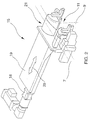
- the side wall adjusting and clamping unit 15 is shown schematically.
- a slide 19 is in the transverse direction of the vehicle by means of a ball screw drive 18 20 movable. With the ball screw drive 18 is a position accuracy achievable of ⁇ 0.02 mm.
- On the carriage 19 is a clamping device 21 arranged which engages the clamping point 11 of the side wall part 5.
- 2 shows the B-pillar 9 of the side wall part 5 in the area of the roof side rail 7 shown in dashed lines.
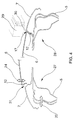
- FIG. 3 the roof part adjusting and tensioning unit 16 is shown schematically.
- a slide 23 is in the vehicle vertical direction by means of a ball screw drive 22 24 movable. With the ball screw drive 22 is a position accuracy of plus / minus 0.02 mm achievable.
- the contour piece 25 corresponds to the area of the roof part 6 in the form customized.
- a section of the roof section is shown in dashed lines.
- FIG. 4 is a schematic section in the transverse direction of the vehicle in the region of the Roof part 6 shown.
- the roof part 6 is still shown lifted off from the side wall part 3.
- This represents the measurement and Alignment position 27 represents a potential regulated with the double arrows Align and adjust the seam, which is formed as a roof joint 17 is drawn in the vehicle transverse direction 20 and in the vehicle vertical direction 24.
- the roof part 6 and the side wall part 5 shown in your laser soldering position 28.
- With a laser soldering head shown in dashed lines 29 a laser solder seam 30 is made along the roof joint 17 for connection of the roof part 6 with the side wall part 5.
- Using cameras 14 the relevant component contours of the roof part 6 and the side wall part 5 recorded, with recorded measurement data as actual values of one not shown here Measuring and control device are supplied. There these actual values compared with contour setpoints and corrective measures determined.
Landscapes
- Engineering & Computer Science (AREA)
- Manufacturing & Machinery (AREA)
- Chemical & Material Sciences (AREA)
- Combustion & Propulsion (AREA)
- Transportation (AREA)
- Mechanical Engineering (AREA)
- Automobile Manufacture Line, Endless Track Vehicle, Trailer (AREA)
Applications Claiming Priority (2)
| Application Number | Priority Date | Filing Date | Title |
|---|---|---|---|
| DE2001163391 DE10163391A1 (de) | 2001-12-21 | 2001-12-21 | Verfahren zur Verbindung von Karosseriebauteilen mit einer Verbindungsnaht |
| DE10163391 | 2001-12-21 |
Publications (3)
| Publication Number | Publication Date |
|---|---|
| EP1321355A2 true EP1321355A2 (fr) | 2003-06-25 |
| EP1321355A3 EP1321355A3 (fr) | 2003-08-27 |
| EP1321355B1 EP1321355B1 (fr) | 2006-07-12 |
Family
ID=7710453
Family Applications (1)
| Application Number | Title | Priority Date | Filing Date |
|---|---|---|---|
| EP20020026615 Expired - Lifetime EP1321355B1 (fr) | 2001-12-21 | 2002-11-29 | Procédé de relier des parties de carrosseries de véhicule avec une ligne de soudure |
Country Status (3)
| Country | Link |
|---|---|
| EP (1) | EP1321355B1 (fr) |
| DE (2) | DE10163391A1 (fr) |
| ES (1) | ES2266392T3 (fr) |
Cited By (8)
| Publication number | Priority date | Publication date | Assignee | Title |
|---|---|---|---|---|
| WO2006133988A3 (fr) * | 2005-06-16 | 2007-03-22 | Thyssenkrupp Drauz Nothelfer | Procede et dispositif pour assembler des pieces d'une carrosserie de vehicule |
| FR2892372A1 (fr) * | 2005-10-25 | 2007-04-27 | Renault Sas | Systeme et procede d'assemblage pour un vehicule |
| US7290831B2 (en) | 2006-04-06 | 2007-11-06 | Gm Global Technology Operations, Inc. | Vehicle with layered roof build |
| DE102005014354B4 (de) * | 2005-03-24 | 2008-04-03 | Thyssenkrupp Drauz Nothelfer Gmbh | Verfahren zur Beeinflussung der Bauteillage bei der Herstellung von zu fügenden/partiell umzuformenden Kraftfahrzeugkarosseriebauteilen |
| CN107414360A (zh) * | 2017-09-20 | 2017-12-01 | 沈阳恒久安泰智能制造与机器人系统技术有限公司 | 一种车体侧墙正面组焊用全自动柔性数控专机 |
| CN114161067A (zh) * | 2022-01-06 | 2022-03-11 | 中车唐山机车车辆有限公司 | 车顶组焊工装 |
| CN114227123A (zh) * | 2021-12-31 | 2022-03-25 | 中车长春轨道客车股份有限公司 | 一种基于三维坐标系的地铁车辆车顶钢结构组焊装置 |
| DE102024115303B3 (de) * | 2024-06-03 | 2025-07-17 | Dr. Ing. H.C. F. Porsche Aktiengesellschaft | Werkstückträger und Verfahren zur Montage von Fahrzeugteilen |
Families Citing this family (2)
| Publication number | Priority date | Publication date | Assignee | Title |
|---|---|---|---|---|
| DE10260909A1 (de) * | 2002-12-20 | 2004-07-01 | Volkswagen Ag | Mess- und Richtstation |
| DE102015005511B4 (de) | 2015-04-30 | 2020-09-24 | Audi Ag | Montageanlage |
Citations (4)
| Publication number | Priority date | Publication date | Assignee | Title |
|---|---|---|---|---|
| DE3720344A1 (de) | 1987-06-19 | 1989-01-05 | Audi Ag | Verfahren zum herstellen einer rohkarosse sowie die rohkarosse selbst |
| DE3346523C2 (de) | 1982-12-22 | 1993-11-25 | Honda Motor Co Ltd | Vorrichtung zum Zusammenbau eines Kraftfahrzeug-Körpers |
| DE19523005A1 (de) | 1994-07-07 | 1996-01-11 | Volkswagen Ag | Fahrzeugkarosserie |
| DE19806963A1 (de) | 1997-03-22 | 1998-10-08 | Thyssen Industrie | Verfahren und Vorrichtung zum Zuführen, Spannen und Bearbeiten, insbesondere zum Geometrie-Schweißen von Bauteilen von Fahrzeugkarosserien in einer Bearbeitungsstation |
Family Cites Families (7)
| Publication number | Priority date | Publication date | Assignee | Title |
|---|---|---|---|---|
| GB2059303B (en) * | 1979-09-25 | 1983-06-02 | Nissan Motor | Two-shift automatic assembling apparatus |
| GB2206316B (en) * | 1987-03-28 | 1991-03-20 | Lamb Technicon Uk Operations C | Holding apparatus for a vehicle assembly line |
| US5374799A (en) * | 1991-01-30 | 1994-12-20 | Mazda Motor Corporation | Method for the assembly of automotive vehicle bodies and a jig unit therefor |
| US5380978A (en) * | 1991-07-12 | 1995-01-10 | Pryor; Timothy R. | Method and apparatus for assembly of car bodies and other 3-dimensional objects |
| DE4418755A1 (de) * | 1994-05-28 | 1995-11-30 | Kuka Schweissanlagen & Roboter | Verfahren und Vorrichtung zum Zuführen, Spannen und Bearbeiten von Bauteilen einer Fahrzeugkarosserie |
| DE19752096B4 (de) * | 1997-11-25 | 2005-03-10 | Thyssenkrupp Drauz Gmbh | Einrichtung zum Positionieren, Spannen und Laserstrahlschweißen von mindestens zwei Blechplatinen |
| DE10026089C2 (de) * | 2000-05-26 | 2003-09-11 | Audi Ag | Verfahren zur Herstellung eines Dachaufbaus einer Rohkarosse eines Kraftfahrzeugs |
-
2001
- 2001-12-21 DE DE2001163391 patent/DE10163391A1/de not_active Withdrawn
-
2002
- 2002-11-29 DE DE50207486T patent/DE50207486D1/de not_active Expired - Lifetime
- 2002-11-29 EP EP20020026615 patent/EP1321355B1/fr not_active Expired - Lifetime
- 2002-11-29 ES ES02026615T patent/ES2266392T3/es not_active Expired - Lifetime
Patent Citations (4)
| Publication number | Priority date | Publication date | Assignee | Title |
|---|---|---|---|---|
| DE3346523C2 (de) | 1982-12-22 | 1993-11-25 | Honda Motor Co Ltd | Vorrichtung zum Zusammenbau eines Kraftfahrzeug-Körpers |
| DE3720344A1 (de) | 1987-06-19 | 1989-01-05 | Audi Ag | Verfahren zum herstellen einer rohkarosse sowie die rohkarosse selbst |
| DE19523005A1 (de) | 1994-07-07 | 1996-01-11 | Volkswagen Ag | Fahrzeugkarosserie |
| DE19806963A1 (de) | 1997-03-22 | 1998-10-08 | Thyssen Industrie | Verfahren und Vorrichtung zum Zuführen, Spannen und Bearbeiten, insbesondere zum Geometrie-Schweißen von Bauteilen von Fahrzeugkarosserien in einer Bearbeitungsstation |
Cited By (12)
| Publication number | Priority date | Publication date | Assignee | Title |
|---|---|---|---|---|
| DE102005014354B4 (de) * | 2005-03-24 | 2008-04-03 | Thyssenkrupp Drauz Nothelfer Gmbh | Verfahren zur Beeinflussung der Bauteillage bei der Herstellung von zu fügenden/partiell umzuformenden Kraftfahrzeugkarosseriebauteilen |
| WO2006133988A3 (fr) * | 2005-06-16 | 2007-03-22 | Thyssenkrupp Drauz Nothelfer | Procede et dispositif pour assembler des pieces d'une carrosserie de vehicule |
| US7854361B2 (en) | 2005-06-16 | 2010-12-21 | Thyssenkrupp Drauz Nothelfer Gmbh | Method and facility for assembling components of a vehicle body |
| FR2892372A1 (fr) * | 2005-10-25 | 2007-04-27 | Renault Sas | Systeme et procede d'assemblage pour un vehicule |
| WO2007048962A1 (fr) * | 2005-10-25 | 2007-05-03 | Renault S.A.S | Systeme et procede d'assemblage pour un vehicule |
| US7290831B2 (en) | 2006-04-06 | 2007-11-06 | Gm Global Technology Operations, Inc. | Vehicle with layered roof build |
| CN107414360A (zh) * | 2017-09-20 | 2017-12-01 | 沈阳恒久安泰智能制造与机器人系统技术有限公司 | 一种车体侧墙正面组焊用全自动柔性数控专机 |
| CN114227123A (zh) * | 2021-12-31 | 2022-03-25 | 中车长春轨道客车股份有限公司 | 一种基于三维坐标系的地铁车辆车顶钢结构组焊装置 |
| CN114227123B (zh) * | 2021-12-31 | 2024-03-22 | 中车长春轨道客车股份有限公司 | 一种基于三维坐标系的地铁车辆车顶钢结构组焊装置 |
| CN114161067A (zh) * | 2022-01-06 | 2022-03-11 | 中车唐山机车车辆有限公司 | 车顶组焊工装 |
| CN114161067B (zh) * | 2022-01-06 | 2024-03-26 | 中车唐山机车车辆有限公司 | 车顶组焊工装 |
| DE102024115303B3 (de) * | 2024-06-03 | 2025-07-17 | Dr. Ing. H.C. F. Porsche Aktiengesellschaft | Werkstückträger und Verfahren zur Montage von Fahrzeugteilen |
Also Published As
| Publication number | Publication date |
|---|---|
| ES2266392T3 (es) | 2007-03-01 |
| EP1321355B1 (fr) | 2006-07-12 |
| EP1321355A3 (fr) | 2003-08-27 |
| DE50207486D1 (de) | 2006-08-24 |
| DE10163391A1 (de) | 2003-07-03 |
Similar Documents
| Publication | Publication Date | Title |
|---|---|---|
| EP0771605B1 (fr) | Procédé de soudure au laser pour des tôles revêtues | |
| DE102012104362B4 (de) | Verfahren zum Steppnahtschweißen einer stirnseitigen Flanschverbindung | |
| EP0838301B1 (fr) | Procédé de soudage de profilages sur des structures d'aluminium de grand format au moyen de faisceau laser et appareil pour exécuter le procédé | |
| DE102007033309A1 (de) | Verfahren zum Bearbeiten einer Kontur an wenigstens einem Werkstück mittels eines Roboters | |
| AT523568B1 (de) | Biegemaschine | |
| EP1537011A2 (fr) | Procede et dispositif pour usiner une piece en mouvement, notamment une carrosserie de vehicule | |
| EP0593719A1 (fr) | Procede et dispositif de montage de portieres dans des carrosseries d'automobiles | |
| DE19734157A1 (de) | Verfahren zum Anbringen der Türscharniere an Kfz-Karosserien und Vorrichtung zur Durchführung des Verfahrens | |
| EP3771502B1 (fr) | Procede et dispositif de formage pour la fabrication d'un composant en tôle comprenant des brides | |
| DE19705278C1 (de) | Verfahren und Vorrichtung zum Laserschweißen | |
| EP2297621B1 (fr) | Procédé et système pour l'application d'une matière de revêtement avec un robot programmable | |
| EP1321355A2 (fr) | Procédé de relier des parties de carrosseries de véhicule avec une ligne de soudure | |
| EP2343231A1 (fr) | Procédé de montage d'un composant de carrosserie sur une carrosserie brute et support | |
| DE4415035A1 (de) | Vorrichtung zum Herstellen von Blechverbindungen durch Nahtschweißen mittels Laserstrahl | |
| WO2018055193A1 (fr) | Outil, machine-outil et procédé d'usinage de pièces en forme de plaque | |
| DE102023003221B3 (de) | Spannvorrichtung für eine Laserschweißvorrichtung und Laserschweißvorrichtung | |
| DE102009024084A1 (de) | Justagevorrichtung und Verfahren zur Justage eines relativ zur Fahrzeugkarosserie zu montierenden Fahrzeugteils | |
| DE102015006421B4 (de) | Verfahren zum Fügen von Bauteilen | |
| EP0711625A1 (fr) | Procédé, appareil et feuillard pour le soudage bout-à-bout de platines de tÔle et appareil pour l'usinage d'au moins un bord d'une platine de tÔle | |
| DE19753103A1 (de) | Verfahren zum Verschweißen zweier plattenförmiger Werkstücke | |
| DE102012004102B4 (de) | Bearbeitungsstation zum Fügen eines Karosseriebauteils an eine Fahrzeugkarosserie | |
| WO2021013810A1 (fr) | Outil et procédé pour l'usinage de pièces en forme de plaques, en particulier de tôles | |
| DE102005009526A1 (de) | Verfahren und Vorrichtung zum Steuern/Regeln der Zustellbewegung eines Fügewerkzeuges | |
| DE102017222090A1 (de) | Vorrichtung und Verfahren zum Zusammenfügen von Zubehörteilen von Dachentwässerungskomponenten | |
| DE102024002504B4 (de) | Verfahren zur Regelung eines Fügeprozesses |
Legal Events
| Date | Code | Title | Description |
|---|---|---|---|
| PUAI | Public reference made under article 153(3) epc to a published international application that has entered the european phase |
Free format text: ORIGINAL CODE: 0009012 |
|
| AK | Designated contracting states |
Designated state(s): AT BE BG CH CY CZ DE DK EE ES FI FR GB GR IE IT LI LU MC NL PT SE SK TR |
|
| AX | Request for extension of the european patent |
Extension state: AL LT LV MK RO SI |
|
| PUAL | Search report despatched |
Free format text: ORIGINAL CODE: 0009013 |
|
| AK | Designated contracting states |
Designated state(s): AT BE BG CH CY CZ DE DK EE ES FI FR GB GR IE IT LI LU MC NL PT SE SK TR |
|
| AX | Request for extension of the european patent |
Extension state: AL LT LV MK RO SI |
|
| RIC1 | Information provided on ipc code assigned before grant |
Ipc: 7B 62D 25/06 A |
|
| 17P | Request for examination filed |
Effective date: 20030828 |
|
| AKX | Designation fees paid |
Designated state(s): DE ES FR GB IT SE |
|
| 17Q | First examination report despatched |
Effective date: 20050509 |
|
| GRAP | Despatch of communication of intention to grant a patent |
Free format text: ORIGINAL CODE: EPIDOSNIGR1 |
|
| GRAS | Grant fee paid |
Free format text: ORIGINAL CODE: EPIDOSNIGR3 |
|
| GRAA | (expected) grant |
Free format text: ORIGINAL CODE: 0009210 |
|
| AK | Designated contracting states |
Kind code of ref document: B1 Designated state(s): DE ES FR GB IT SE |
|
| PG25 | Lapsed in a contracting state [announced via postgrant information from national office to epo] |
Ref country code: IT Free format text: LAPSE BECAUSE OF FAILURE TO SUBMIT A TRANSLATION OF THE DESCRIPTION OR TO PAY THE FEE WITHIN THE PRESCRIBED TIME-LIMIT;WARNING: LAPSES OF ITALIAN PATENTS WITH EFFECTIVE DATE BEFORE 2007 MAY HAVE OCCURRED AT ANY TIME BEFORE 2007. THE CORRECT EFFECTIVE DATE MAY BE DIFFERENT FROM THE ONE RECORDED. Effective date: 20060712 |
|
| REG | Reference to a national code |
Ref country code: GB Ref legal event code: FG4D Free format text: NOT ENGLISH |
|
| REF | Corresponds to: |
Ref document number: 50207486 Country of ref document: DE Date of ref document: 20060824 Kind code of ref document: P |
|
| REG | Reference to a national code |
Ref country code: SE Ref legal event code: TRGR |
|
| GBT | Gb: translation of ep patent filed (gb section 77(6)(a)/1977) |
Effective date: 20061124 |
|
| ET | Fr: translation filed | ||
| REG | Reference to a national code |
Ref country code: ES Ref legal event code: FG2A Ref document number: 2266392 Country of ref document: ES Kind code of ref document: T3 |
|
| PLBE | No opposition filed within time limit |
Free format text: ORIGINAL CODE: 0009261 |
|
| STAA | Information on the status of an ep patent application or granted ep patent |
Free format text: STATUS: NO OPPOSITION FILED WITHIN TIME LIMIT |
|
| 26N | No opposition filed |
Effective date: 20070413 |
|
| REG | Reference to a national code |
Ref country code: FR Ref legal event code: PLFP Year of fee payment: 14 |
|
| REG | Reference to a national code |
Ref country code: FR Ref legal event code: PLFP Year of fee payment: 15 |
|
| REG | Reference to a national code |
Ref country code: FR Ref legal event code: PLFP Year of fee payment: 16 |
|
| PGFP | Annual fee paid to national office [announced via postgrant information from national office to epo] |
Ref country code: SE Payment date: 20181024 Year of fee payment: 10 |
|
| PGFP | Annual fee paid to national office [announced via postgrant information from national office to epo] |
Ref country code: ES Payment date: 20181214 Year of fee payment: 17 Ref country code: IT Payment date: 20181130 Year of fee payment: 17 |
|
| PGFP | Annual fee paid to national office [announced via postgrant information from national office to epo] |
Ref country code: DE Payment date: 20191130 Year of fee payment: 18 |
|
| PGFP | Annual fee paid to national office [announced via postgrant information from national office to epo] |
Ref country code: FR Payment date: 20191124 Year of fee payment: 18 |
|
| PGFP | Annual fee paid to national office [announced via postgrant information from national office to epo] |
Ref country code: GB Payment date: 20191122 Year of fee payment: 18 |
|
| REG | Reference to a national code |
Ref country code: SE Ref legal event code: EUG |
|
| PG25 | Lapsed in a contracting state [announced via postgrant information from national office to epo] |
Ref country code: SE Free format text: LAPSE BECAUSE OF NON-PAYMENT OF DUE FEES Effective date: 20191130 |
|
| PG25 | Lapsed in a contracting state [announced via postgrant information from national office to epo] |
Ref country code: IT Free format text: LAPSE BECAUSE OF NON-PAYMENT OF DUE FEES Effective date: 20191129 |
|
| REG | Reference to a national code |
Ref country code: ES Ref legal event code: FD2A Effective date: 20210531 |
|
| REG | Reference to a national code |
Ref country code: DE Ref legal event code: R119 Ref document number: 50207486 Country of ref document: DE |
|
| GBPC | Gb: european patent ceased through non-payment of renewal fee |
Effective date: 20201129 |
|
| PG25 | Lapsed in a contracting state [announced via postgrant information from national office to epo] |
Ref country code: ES Free format text: LAPSE BECAUSE OF NON-PAYMENT OF DUE FEES Effective date: 20191130 |
|
| PG25 | Lapsed in a contracting state [announced via postgrant information from national office to epo] |
Ref country code: FR Free format text: LAPSE BECAUSE OF NON-PAYMENT OF DUE FEES Effective date: 20201130 |
|
| PG25 | Lapsed in a contracting state [announced via postgrant information from national office to epo] |
Ref country code: DE Free format text: LAPSE BECAUSE OF NON-PAYMENT OF DUE FEES Effective date: 20210601 Ref country code: GB Free format text: LAPSE BECAUSE OF NON-PAYMENT OF DUE FEES Effective date: 20201129 |