EP2343231A1 - Procédé de montage d'un composant de carrosserie sur une carrosserie brute et support - Google Patents
Procédé de montage d'un composant de carrosserie sur une carrosserie brute et support Download PDFInfo
- Publication number
- EP2343231A1 EP2343231A1 EP11150358A EP11150358A EP2343231A1 EP 2343231 A1 EP2343231 A1 EP 2343231A1 EP 11150358 A EP11150358 A EP 11150358A EP 11150358 A EP11150358 A EP 11150358A EP 2343231 A1 EP2343231 A1 EP 2343231A1
- Authority
- EP
- European Patent Office
- Prior art keywords
- coordinate
- vehicle
- respect
- receptacle
- reference point
- Prior art date
- Legal status (The legal status is an assumption and is not a legal conclusion. Google has not performed a legal analysis and makes no representation as to the accuracy of the status listed.)
- Withdrawn
Links
- 238000000034 method Methods 0.000 title claims abstract description 33
- 238000005259 measurement Methods 0.000 claims abstract description 9
- 238000003466 welding Methods 0.000 claims description 8
- 239000002184 metal Substances 0.000 claims description 4
- 238000004519 manufacturing process Methods 0.000 description 5
- 238000009434 installation Methods 0.000 description 4
- 238000003780 insertion Methods 0.000 description 3
- 230000037431 insertion Effects 0.000 description 3
- 238000011161 development Methods 0.000 description 2
- 230000018109 developmental process Effects 0.000 description 2
- 241000972773 Aulopiformes Species 0.000 description 1
- 238000004026 adhesive bonding Methods 0.000 description 1
- 230000015572 biosynthetic process Effects 0.000 description 1
- 238000001816 cooling Methods 0.000 description 1
- 238000012937 correction Methods 0.000 description 1
- 239000000945 filler Substances 0.000 description 1
- 238000005304 joining Methods 0.000 description 1
- 239000000463 material Substances 0.000 description 1
- 230000007935 neutral effect Effects 0.000 description 1
- 230000003287 optical effect Effects 0.000 description 1
- 235000019515 salmon Nutrition 0.000 description 1
- 238000005476 soldering Methods 0.000 description 1
- 230000006641 stabilisation Effects 0.000 description 1
- 238000011105 stabilization Methods 0.000 description 1
- 230000007704 transition Effects 0.000 description 1
Images



Classifications
-
- B—PERFORMING OPERATIONS; TRANSPORTING
- B62—LAND VEHICLES FOR TRAVELLING OTHERWISE THAN ON RAILS
- B62D—MOTOR VEHICLES; TRAILERS
- B62D65/00—Designing, manufacturing, e.g. assembling, facilitating disassembly, or structurally modifying motor vehicles or trailers, not otherwise provided for
- B62D65/02—Joining sub-units or components to, or positioning sub-units or components with respect to, body shell or other sub-units or components
- B62D65/024—Positioning of sub-units or components with respect to body shell or other sub-units or components
- B62D65/028—Positioning of sub-units or components with respect to body shell or other sub-units or components by determining relative positions by measurement
-
- Y—GENERAL TAGGING OF NEW TECHNOLOGICAL DEVELOPMENTS; GENERAL TAGGING OF CROSS-SECTIONAL TECHNOLOGIES SPANNING OVER SEVERAL SECTIONS OF THE IPC; TECHNICAL SUBJECTS COVERED BY FORMER USPC CROSS-REFERENCE ART COLLECTIONS [XRACs] AND DIGESTS
- Y10—TECHNICAL SUBJECTS COVERED BY FORMER USPC
- Y10T—TECHNICAL SUBJECTS COVERED BY FORMER US CLASSIFICATION
- Y10T29/00—Metal working
- Y10T29/49—Method of mechanical manufacture
- Y10T29/49616—Structural member making
- Y10T29/49622—Vehicular structural member making
-
- Y—GENERAL TAGGING OF NEW TECHNOLOGICAL DEVELOPMENTS; GENERAL TAGGING OF CROSS-SECTIONAL TECHNOLOGIES SPANNING OVER SEVERAL SECTIONS OF THE IPC; TECHNICAL SUBJECTS COVERED BY FORMER USPC CROSS-REFERENCE ART COLLECTIONS [XRACs] AND DIGESTS
- Y10—TECHNICAL SUBJECTS COVERED BY FORMER USPC
- Y10T—TECHNICAL SUBJECTS COVERED BY FORMER US CLASSIFICATION
- Y10T29/00—Metal working
- Y10T29/49—Method of mechanical manufacture
- Y10T29/49764—Method of mechanical manufacture with testing or indicating
-
- Y—GENERAL TAGGING OF NEW TECHNOLOGICAL DEVELOPMENTS; GENERAL TAGGING OF CROSS-SECTIONAL TECHNOLOGIES SPANNING OVER SEVERAL SECTIONS OF THE IPC; TECHNICAL SUBJECTS COVERED BY FORMER USPC CROSS-REFERENCE ART COLLECTIONS [XRACs] AND DIGESTS
- Y10—TECHNICAL SUBJECTS COVERED BY FORMER USPC
- Y10T—TECHNICAL SUBJECTS COVERED BY FORMER US CLASSIFICATION
- Y10T29/00—Metal working
- Y10T29/49—Method of mechanical manufacture
- Y10T29/49764—Method of mechanical manufacture with testing or indicating
- Y10T29/49771—Quantitative measuring or gauging
-
- Y—GENERAL TAGGING OF NEW TECHNOLOGICAL DEVELOPMENTS; GENERAL TAGGING OF CROSS-SECTIONAL TECHNOLOGIES SPANNING OVER SEVERAL SECTIONS OF THE IPC; TECHNICAL SUBJECTS COVERED BY FORMER USPC CROSS-REFERENCE ART COLLECTIONS [XRACs] AND DIGESTS
- Y10—TECHNICAL SUBJECTS COVERED BY FORMER USPC
- Y10T—TECHNICAL SUBJECTS COVERED BY FORMER US CLASSIFICATION
- Y10T29/00—Metal working
- Y10T29/49—Method of mechanical manufacture
- Y10T29/49764—Method of mechanical manufacture with testing or indicating
- Y10T29/49778—Method of mechanical manufacture with testing or indicating with aligning, guiding, or instruction
-
- Y—GENERAL TAGGING OF NEW TECHNOLOGICAL DEVELOPMENTS; GENERAL TAGGING OF CROSS-SECTIONAL TECHNOLOGIES SPANNING OVER SEVERAL SECTIONS OF THE IPC; TECHNICAL SUBJECTS COVERED BY FORMER USPC CROSS-REFERENCE ART COLLECTIONS [XRACs] AND DIGESTS
- Y10—TECHNICAL SUBJECTS COVERED BY FORMER USPC
- Y10T—TECHNICAL SUBJECTS COVERED BY FORMER US CLASSIFICATION
- Y10T29/00—Metal working
- Y10T29/49—Method of mechanical manufacture
- Y10T29/49764—Method of mechanical manufacture with testing or indicating
- Y10T29/49778—Method of mechanical manufacture with testing or indicating with aligning, guiding, or instruction
- Y10T29/4978—Assisting assembly or disassembly
-
- Y—GENERAL TAGGING OF NEW TECHNOLOGICAL DEVELOPMENTS; GENERAL TAGGING OF CROSS-SECTIONAL TECHNOLOGIES SPANNING OVER SEVERAL SECTIONS OF THE IPC; TECHNICAL SUBJECTS COVERED BY FORMER USPC CROSS-REFERENCE ART COLLECTIONS [XRACs] AND DIGESTS
- Y10—TECHNICAL SUBJECTS COVERED BY FORMER USPC
- Y10T—TECHNICAL SUBJECTS COVERED BY FORMER US CLASSIFICATION
- Y10T29/00—Metal working
- Y10T29/49—Method of mechanical manufacture
- Y10T29/49826—Assembling or joining
Definitions
- the invention relates to a method for mounting a body component to a body shell of a vehicle with side walls.
- the invention further relates to a holder, in particular for use in this method.
- Lamps, fenders, grille, luggage compartment cover and bonnet should form as small as possible, preferably parallel, gaps with as few variations as possible in the mounting position. Likewise, matching levels are subject to similar requirements. Therefore, the body part must be installed during installation very accurately in the body shell. Subsequent corrections can only be carried out very costly.
- a stronger modularization in the automotive industry means that pre-assembled units are used in which form deviations can be summed up as a result of preassembled body parts, which makes the installation of these units in compliance with the required gap and Passungstruckes much more difficult.
- a unit is for example the front of the vehicle, which may consist of radiator frame, cooling package, hood lock and headlamps to the bumpers.
- the invention has the object of developing the aforementioned method for mounting a body component to a body of a vehicle so that a less expensive and cheaper cost assembly of the body components is possible.
- the process should also be feasible in less technical production facilities.
- the measuring of the actual position of at least one partial area of at least one of the side walls in the body shell relative to at least one first coordinate of the vehicle can be carried out without contact.
- the actual position is measured by means of a laser measuring measuring device.
- the actual position of at least one subarea of the two side walls, such as their A, B and / or C pillars, in the body shell relative to at least a first coordinate of the vehicle is detected. From this, for example, with respect to the first coordinate, an actual zero point can be determined as the center of the vehicle.
- the reference point can then be set by means of a simple centering device and then set to refer to the actual vehicle center with respect to the first coordinate.
- the zero point determination can also serve as a basis for determining and positioning other reference points with respect to the respective coordinate to which the zero point refers. This can be particularly advantageous in mirror-symmetrically arranged body components and / or in body components which are arranged between two mirror-symmetrically arranged body components.
- the method according to the invention is equally suitable for determining at least one reference point with respect to at least one arbitrary coordinate of the vehicle.
- the reference point for the body part to be mounted can be determined with respect to a second and / or a third coordinate of the vehicle, wherein the first, second and third coordinates are preferably perpendicular to stand by each other.
- a further, already created reference point is used with respect to the further coordinate for another body part to be mounted prior to its determination on the body shell.
- reference points of adjacent body components are particularly suitable because of their relatively small distance to be created reference point.
- the actual position of two preassembled body components can be detected with respect to at least the first coordinate and from this a certain reference point, such as the zero point, can be determined, relative to which the reference point for the body part to be mounted can be arranged. In both cases, additional possible assembly deviations of the previously assembled body component or the previously assembled body components can be compensated.
- the creation of at least one reference point with respect to at least the first coordinate of the vehicle for the body part to be mounted can be carried out on the basis of the measurement and attachment of the body component to be mounted relative to this at least one reference point.
- the at least one reference point with respect to the first coordinate can be formed by means of an insert component which is positioned on the body shell on the basis of the measurement.
- the insert member is positioned on a supporting part of the body shell, such as side members and cross member.
- the insert component may be temporarily, for example, for the installation period of the body part, or permanently fixed to the body become.
- the insert member may be formed as a holder.
- the holder may have a receptacle and / or a stop with the reference point for a positioning element or a positioning portion of the body part to be mounted.
- the positioning element or the positioning section of the body component to be mounted can be received in the receptacle or guided against the stop.
- the positioning element has at least one pin-like section for engagement in the receptacle.
- the receptacle can have a recess or recess with a depth dimension.
- the holder can be fixed to the body such that the depth dimension extends at least approximately perpendicular to the first coordinate in the direction of a second coordinate of the vehicle.
- the second coordinate of the vehicle preferably runs perpendicular to the first coordinate and a third coordinate of the vehicle.
- the reference point with respect to the second coordinate can be adjusted via the size of the depth dimension.
- the recording can be designed with an adjustable depth dimension.
- the holder may have a plurality of different shots with respect to the depth dimension, wherein a shot is selected based on the measurement relative to the second coordinate. It can also be provided different holders in the production process, each having a different depth dimension. The provision, positioning and / or fixing of the suitable holder can be done automatically on the basis of the survey.
- the recording may have a recording reason.
- the receiving cross-section of the receptacle may taper in the direction of the depth dimension or the reason for the reception. In this way, a funnel or wedge-like guide for easier insertion of the positioning or positioning can be provided.
- the holder is designed as a sheet metal strip. It preferably has an end-face-side receptacle.
- the receptacle may comprise a receiving slot, which opens laterally and preferably perpendicularly into the larger side surfaces of the sheet metal strip.
- the holder can be positioned on the body such that the receiving slot extends laterally in the direction of the third coordinate.
- a plug and / or snap connection may be provided.
- the positioning element or the positioning section is arranged in a form-fitting manner in the receiving slot.
- the receiving cross section may be formed in the region of the receiving base such that the associated positioning element or the associated positioning section of the body component to be mounted rests laterally positively against the side walls of the receptacle and / or rests against the receiving base , As a result, a fixed position of the positioning element or of the positioning section in the receptacle can be achieved with respect to the first coordinate.
- the receiving floor can serve as a reference point.
- the insert component or the holder can be fixed to the body shell by means of a conventional joining method, such as welding, gluing or soldering.
- the insert component or the holder is preferably fixed to the body by means of laser welding or arc welding, for example by the Weldfast method.
- the strip-like holder may have an angled foot for support and attachment to the body shell.
- the strip-like holder is designed as a salmon with a stretched foot, which by means of Weldfast process without welding filler material can be directly bonded cohesively to the body shell.
- the three coordinates of the X-coordinate i. the vehicle length, the Y coordinate, i. the vehicle width and Z coordinate, i. the vehicle height, be assigned. Which of these coordinates is considered to be the first coordinate, the second coordinate or the third coordinate ultimately depends on the position of the body component to be mounted and thus on the coordinate to be determined. It is obvious that the relative position of the side walls with respect to two or all three coordinates can be measured in order to make a determination of the actual center of the vehicle with respect to the side walls with respect to the two or all three coordinates and relative thereto the required To attach reference points for the body to be assembled or the body parts to be mounted to the body shell.
- the body component may be a single component or composed of two or more prefabricated components.
- the body component may be a prefabricated module.
- the method according to the invention for mounting a body component, which is fixed to the underbody group and to at least one side wall, is particularly suitable, since the deviations considered at the outset are particularly significant here.
- the body component to be installed may be the front of the vehicle, which may be formed as a module with at least a portion of the components described above.
- the actual position of at least a portion of the two side walls and here preferably the A-pillars in the body shell measured.
- the measurement is preferably carried out with respect to the width of the vehicle, so the Y-coordinate.
- an actual Y o point can be determined as the vehicle center, relative to which the reference point can preferably be set on the sub-floor group.
- the determination of the X-coordinate of the front end can be done by means of the end stop of the front carriage against the direction of travel, ie in the negative X direction of the vehicle, against the underbody group, in particular against the longitudinal member and / or front cross member.
- the positioning of the at least one Reference point is fixed with respect to the X-coordinate of the front end by means of this end-side stop on at least one side rail and / or front cross member.
- the measurement can also be carried out with respect to at least one of the other coordinates. It is preferably provided that, for the determination of the at least one reference point with respect to the X-coordinate and / or Z-coordinate, coordinates of at least one already established reference point for the fender and / or engine hood is used.
- a reference point with respect to the Y-coordinate can be provided for positioning the front of the vehicle via the insert member, which is arranged according to the measured actual position of the side walls of the sub-floor group.
- a Z-coordinate can be determined via the formation of the recording of the holder.
- the Z coordinate can additionally be defined in a further reference point, preferably on both side walls.
- the X-coordinate can, as described above, be determined by means of stop of the front end against the sub-floor group.
- the four-stroke front carriage can be fully aligned with respect to the X coordinate, two mountings for preferably positioning pins or needles as positioning elements with respect to the Z coordinate, and a receptacle for preferably positioning pins or needles as positioning elements with respect to the Y coordinate to the sidewalls , As a result, an optimal gap and Passungstruck can be ensured.
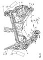
- FIGS. 1 and 3 In each case, a perspective top view is reproduced on a front part of a body shell 1 of a vehicle 2 with side walls 3 and underbody group 4 in the direction of travel f.
- the embodiment according to FIG. 1a differs from the embodiment according to FIG. 1b only in the embodiment of a reference point.
- FIG. 3 additionally assembled body components, here both front fenders 5 and a support frame 6 of a front carriage 7 not shown here are shown in more detail.
- FIG. 2 is a section according to FIG. 1 shown.
- R 1 and R 2 are provided as abutment points with respect to the X-coordinate x, the Y-coordinate y and the Z-coordinate z during assembly. Thanks to the reference points R 1 , R 2 and R 3 of the support frame 6 and thus the front to be mounted on the same 7 can be accurately positioned during assembly.
- a reference point R 2 is positioned on a side wall 3.
- FIG. 1a are different reference points R 1 and R 3 in the direction of travel f on the longitudinal members 9 of the sub-floor group 4 arranged.
- the starting point is the body shell 1 with subfloor group 4 and longitudinal members 9:
- the subarea is in each case the A-pillar 10 and the first coordinate the Y-coordinate y.
- the y-coordinate y describes the vehicle width.
- the actual position of both A-pillars 10 with respect to the Y-coordinate y is detected without contact by means of a measuring device 11 operating with laser L.
- an actual vehicle center y 0 is calculated with respect to the Y coordinate.
- the actual position of the side walls 3 with respect to the actual vehicle center y 0 or their spacing from the same is indicated in the drawing by + Y 0.5 or -Y 0.5 .
- a second step at least one reference point, in this case the reference point R 1 , here with respect to the Y-coordinate y of the vehicle 2 for the front end 7 or its support frame 6 is created on the basis of determining the actual position of the side walls 3.
- the reference point R 1 the position of the front carriage 7 with respect to the Y-coordinate is determined.
- the assembly of the front carriage 7 and the support frame 6 of the front carriage 7 takes place. Since the positioning of the reference point R 1 on the longitudinal member 9 bez. the longitudinal beams 9 refers to the actual position of the side walls 3 and to the determined therefrom actual vehicle center y 0 , the above deviation are compensated. This can be achieved with the assembly of front end 7 and the adjacent body panels, ie fender 5 and not shown here bonnet, an optimal gap and Passungstruck.
- the reference point R 2 is here in each case with respect to the Z-coordinate z, ie the vehicle height, and the X-coordinate x, ie the vehicle length, on the side walls 3 determines.
- reference point R 3 according to FIG. 1 a is the x-coordinate x fixed by stop 12 to the longitudinal member 9.
- the reference point R 1 is also fixed here with respect to the X-coordinate x by stop 12 on the longitudinal member 9.
- an insertion component 14 designed as a holder 13 is provided.
- the holder 13 is fixedly mounted according to the determined distance + Y 0.5 or -Y 0.5 of the actual vehicle center y 0 on the longitudinal member 9, that is, here welded by means of the Weldfast method with the same.
- the holder 13 is formed as a sheet-metal strip-like with larger side surfaces 16, wherein it is laterally bent around its shape stabilization. It remains after the assembly of the front carriage 7 as a potential deformation part on the longitudinal member 9.
- the holder 13 has a receiving slot 16 with depth dimension t formed receptacle 17.
- the receiving slot 16 is aligned so that it opens laterally in the direction of travel f in the larger side surfaces 16.
- the narrow inner side walls 18 of the receiving slot 16 are arranged approximately perpendicular to the Y-coordinate y on the longitudinal member 9.
- the receiving slot 16 opens in the direction of the Z coordinate.
- the holder 13 is in the embodiment according to FIG. 1a on the left side member 9 there and in the embodiment according to Figure 1 b on mounted on both side members 9.
- positioning pin 20 For positioning of the front carriage 7 on the body shell 1 engages, as in FIG. 3 indicated by dashed lines, provided on the support frame 6 positioning element 19 with a positioning pin 20 approximately in the direction of the Z coordinate in the receiving slot 16 of the holder 13 a. Introduced into the receiving slot 16, the positioning pin 20 rests on the receiving base 21 and with respect to the Y-coordinate positively against the inner side walls 18 at. As a result, the positioning pin 20 is fixed relative to the Y-coordinate y on the longitudinal member 9. For easier insertion of the positioning pin 20 in the receiving slot 16, the same is extended upward and rounded.
- the Z coordinate z is set in this point by the relative position of the receiving base 21 to the side member 9. Since a holder 13 is used here with a specific position of the receiving base 21, this does not take into account the relative position of the two side walls 3 with respect to the Z coordinate z.
- an insert component with adjustable point for determining the Z coordinate in dependence on the relative position of the side walls 3 with respect to the Z coordinate z.
- the receiving reason of the holder may be designed to be adjustable in height.
- the holder may have a plurality of receptacles with different levels of reception reasons, of which a specific receptacle is used on account of the measurement of the relative position of the side parts.
Landscapes
- Engineering & Computer Science (AREA)
- Manufacturing & Machinery (AREA)
- Chemical & Material Sciences (AREA)
- Combustion & Propulsion (AREA)
- Transportation (AREA)
- Mechanical Engineering (AREA)
- Automobile Manufacture Line, Endless Track Vehicle, Trailer (AREA)
- Body Structure For Vehicles (AREA)
Applications Claiming Priority (1)
| Application Number | Priority Date | Filing Date | Title |
|---|---|---|---|
| DE102010000777A DE102010000777A1 (de) | 2010-01-11 | 2010-01-11 | Verfahren zur Montage eines Karosseriebauteils an eine Rohkarosserie und Halter |
Publications (1)
| Publication Number | Publication Date |
|---|---|
| EP2343231A1 true EP2343231A1 (fr) | 2011-07-13 |
Family
ID=43629460
Family Applications (1)
| Application Number | Title | Priority Date | Filing Date |
|---|---|---|---|
| EP11150358A Withdrawn EP2343231A1 (fr) | 2010-01-11 | 2011-01-07 | Procédé de montage d'un composant de carrosserie sur une carrosserie brute et support |
Country Status (4)
| Country | Link |
|---|---|
| US (1) | US8555478B2 (fr) |
| EP (1) | EP2343231A1 (fr) |
| CN (1) | CN102120470B (fr) |
| DE (1) | DE102010000777A1 (fr) |
Cited By (1)
| Publication number | Priority date | Publication date | Assignee | Title |
|---|---|---|---|---|
| CN114261463A (zh) * | 2021-12-16 | 2022-04-01 | 东风汽车集团股份有限公司 | 橫置动力总成快速搭载硬点选择方法 |
Families Citing this family (8)
| Publication number | Priority date | Publication date | Assignee | Title |
|---|---|---|---|---|
| EP2700570A1 (fr) * | 2012-08-20 | 2014-02-26 | Hexagon Metrology S.p.A. | Dispositif et procédé de positionnement mécanique |
| US9157720B2 (en) * | 2012-08-31 | 2015-10-13 | GM Global Technology Operations LLC | Dimensional centering structure for a vehicle and method of establishing a dimensional reference datum |
| DE102014013724A1 (de) | 2014-09-22 | 2016-03-24 | Andreas Enders | Verfahren zum Abstecken von Bohrlöchern eines Fahrzeugs |
| DE102016002889A1 (de) * | 2016-03-09 | 2017-09-14 | GM Global Technology Operations LLC (n. d. Ges. d. Staates Delaware) | Verfahren zur Vermeidung von Kantenrissen |
| CN107458501B (zh) * | 2017-08-14 | 2019-04-23 | 中车唐山机车车辆有限公司 | 双层车体装配系统及方法 |
| EP3546321B1 (fr) | 2018-03-29 | 2023-01-18 | Volvo Car Corporation | Procédé de formation d'un ensemble de véhicule |
| CN116252256B (zh) * | 2023-01-09 | 2026-05-12 | 东实(武汉)汽车零部件有限公司 | 一种用于多车型侧围类零件尺寸测量的三坐标支架设备 |
| DE102024111431A1 (de) | 2024-04-24 | 2025-10-30 | Bayerische Motoren Werke Aktiengesellschaft | Verfahren zur Herstellung einer Baugruppe und Baugruppe |
Citations (7)
| Publication number | Priority date | Publication date | Assignee | Title |
|---|---|---|---|---|
| DE4216606A1 (de) | 1992-05-20 | 1993-11-25 | Ammendorf Waggonbau | Verfahren zur Fertigung und zum Ausbau von Schienenfahrzeugwagenkästen mit hoher Maßgenauigkeit |
| EP1036730A2 (fr) * | 1999-03-18 | 2000-09-20 | Volkswagen Aktiengesellschaft | Procedé pour le montage avec tolérance de précision des composants de la partie antèrieure d'un véhicule ainsi que le dispositif de mise en place de ce procédé |
| DE10135158A1 (de) * | 2001-07-19 | 2003-02-06 | Audi Ag | Verfahren zur Montage von Schottplatten an Längsträgern eines Fahrzeugs, insbesondere eines Kraftfahrzeugs |
| DE10215708A1 (de) * | 2002-04-10 | 2003-11-06 | Karmann Gmbh W | Vorrichtung und Verfahren zum Positionieren und Befestigen eines flächigen Körpers an einem Bezugskörper |
| WO2006123077A1 (fr) * | 2005-05-18 | 2006-11-23 | Renault S.A.S | Dispositif pour le montage d'une piece sur la caisse d'un vehicule automobile |
| US7143494B2 (en) | 2001-05-16 | 2006-12-05 | Utica Enterprises, Inc. | Method and apparatus for assembling exterior automotive vehicle body components onto an automotive vehicle body |
| WO2009071244A1 (fr) * | 2007-12-06 | 2009-06-11 | Bayerische Motoren Werke Aktiengesellschaft | Carrosserie de véhicule équipée d'un élément de carrosserie |
Family Cites Families (1)
| Publication number | Priority date | Publication date | Assignee | Title |
|---|---|---|---|---|
| US6691392B2 (en) * | 2001-05-16 | 2004-02-17 | Utica Enterprises, Inc. | Method and apparatus for assembling exterior automotive vehicle body components onto an automotive vehicle body |
-
2010
- 2010-01-11 DE DE102010000777A patent/DE102010000777A1/de not_active Withdrawn
- 2010-12-30 CN CN201010615216.0A patent/CN102120470B/zh not_active Expired - Fee Related
-
2011
- 2011-01-06 US US12/985,785 patent/US8555478B2/en not_active Expired - Fee Related
- 2011-01-07 EP EP11150358A patent/EP2343231A1/fr not_active Withdrawn
Patent Citations (7)
| Publication number | Priority date | Publication date | Assignee | Title |
|---|---|---|---|---|
| DE4216606A1 (de) | 1992-05-20 | 1993-11-25 | Ammendorf Waggonbau | Verfahren zur Fertigung und zum Ausbau von Schienenfahrzeugwagenkästen mit hoher Maßgenauigkeit |
| EP1036730A2 (fr) * | 1999-03-18 | 2000-09-20 | Volkswagen Aktiengesellschaft | Procedé pour le montage avec tolérance de précision des composants de la partie antèrieure d'un véhicule ainsi que le dispositif de mise en place de ce procédé |
| US7143494B2 (en) | 2001-05-16 | 2006-12-05 | Utica Enterprises, Inc. | Method and apparatus for assembling exterior automotive vehicle body components onto an automotive vehicle body |
| DE10135158A1 (de) * | 2001-07-19 | 2003-02-06 | Audi Ag | Verfahren zur Montage von Schottplatten an Längsträgern eines Fahrzeugs, insbesondere eines Kraftfahrzeugs |
| DE10215708A1 (de) * | 2002-04-10 | 2003-11-06 | Karmann Gmbh W | Vorrichtung und Verfahren zum Positionieren und Befestigen eines flächigen Körpers an einem Bezugskörper |
| WO2006123077A1 (fr) * | 2005-05-18 | 2006-11-23 | Renault S.A.S | Dispositif pour le montage d'une piece sur la caisse d'un vehicule automobile |
| WO2009071244A1 (fr) * | 2007-12-06 | 2009-06-11 | Bayerische Motoren Werke Aktiengesellschaft | Carrosserie de véhicule équipée d'un élément de carrosserie |
Cited By (1)
| Publication number | Priority date | Publication date | Assignee | Title |
|---|---|---|---|---|
| CN114261463A (zh) * | 2021-12-16 | 2022-04-01 | 东风汽车集团股份有限公司 | 橫置动力总成快速搭载硬点选择方法 |
Also Published As
| Publication number | Publication date |
|---|---|
| US8555478B2 (en) | 2013-10-15 |
| CN102120470B (zh) | 2015-11-18 |
| CN102120470A (zh) | 2011-07-13 |
| US20110167608A1 (en) | 2011-07-14 |
| DE102010000777A1 (de) | 2011-07-14 |
Similar Documents
| Publication | Publication Date | Title |
|---|---|---|
| DE102010000777A1 (de) | Verfahren zur Montage eines Karosseriebauteils an eine Rohkarosserie und Halter | |
| DE102011054540B4 (de) | Laser-überlappschweissverfahren für teile aus verzinktem stahlblech | |
| DE102013200928B4 (de) | Vorrichtung für die Fixierung und/oder Justierung von Karosseriebauteilensowie Verfahren dazu | |
| DE102014115229A1 (de) | Klemme und Kopplungsbaugruppe | |
| DE102006043981B4 (de) | Fahrzeugkarosserieblech, insbesondere Fahrzeugunterboden | |
| DE102013003074B4 (de) | Montagevorrichtung zur Montage von fahrzeugkarosserieseitigen Scharnierteilen bzw. Scharnieren für ein Fahrzeug sowie Verfahren zur Montage | |
| DE102014216332A1 (de) | Vorrichtung zur Ausrichtung eines Anbauteils, insbesondere eines Stoßfängers, an ein Fahrzeug und Verfahren | |
| DE102015119229A1 (de) | Instrumententräger zur Halterung eines Anbauteils in einem Kraftfahrzeug | |
| DE102018128402A1 (de) | Verfahren zur Herstellung einer Laserschweißverbindung | |
| DE102012022783A1 (de) | Befestigungsanordnung an einem Fahrzeug sowie Fahrzeug | |
| EP1180410A2 (fr) | Assemblage soudé de deux tôles minces | |
| DE102015010578A1 (de) | Verfahren zur Montage einer Instrumententafel an einer Fahrzeugkarosserie sowie hierbei verwendete Vorrichtung und verwendeter Zentrierbolzen | |
| EP1321355A2 (fr) | Procédé de relier des parties de carrosseries de véhicule avec une ligne de soudure | |
| DE10248169B4 (de) | Vorrichtung zum lagegenauen Einbau eines Montageträgers für eine Schalttafel in ein Kraftfahrzeug | |
| DE102017219534A1 (de) | Verfahren zum Herstellen einer Überlappungsverbindung und Karosseriebauteil für ein Fahrzeug | |
| DE10135158B4 (de) | Verfahren zur Montage von Schottplatten an Längsträgern eines Fahrzeugs, insbesondere eines Kraftfahrzeugs | |
| DE102016200646B4 (de) | Verfahren zum Verschweißen eines bolzenartigen Bauteils mit einem Basisbauteil | |
| DE102004008108B4 (de) | Überlappstoß zum Schweißen von beschichteten Werkstücken | |
| DE102010051357A1 (de) | Halteanordnung für einen Stoßfänger und Verfahren zum Montieren eines Stoßfängers | |
| DE102022001645A1 (de) | Verfahren zur optischen Analyse einer mindestens zwei sich überlappende Fügepartner verbindenden Schweißnaht | |
| DE102007008641A1 (de) | Knotenstruktur aus geschlossenen Hohlprofilen | |
| DE19753103A1 (de) | Verfahren zum Verschweißen zweier plattenförmiger Werkstücke | |
| DE102016003801B4 (de) | Verfahren zur Herstellung einer Fügeverbindung durch Schweißen und nach dem Verfahren hergestellte Fügeverbindung sowie eine Bauteilgruppe mit gemäß dem Verfahren gefügten Bauteilen | |
| DE102024110875B3 (de) | Verfahren zum Herstellen von Kraftfahrzeugen | |
| EP2689985A1 (fr) | Renfort d'un élément plat, notamment d'un élément de paroi extérieure d'un véhicule guidé |
Legal Events
| Date | Code | Title | Description |
|---|---|---|---|
| PUAI | Public reference made under article 153(3) epc to a published international application that has entered the european phase |
Free format text: ORIGINAL CODE: 0009012 |
|
| AK | Designated contracting states |
Kind code of ref document: A1 Designated state(s): AL AT BE BG CH CY CZ DE DK EE ES FI FR GB GR HR HU IE IS IT LI LT LU LV MC MK MT NL NO PL PT RO RS SE SI SK SM TR |
|
| AX | Request for extension of the european patent |
Extension state: BA ME |
|
| 17P | Request for examination filed |
Effective date: 20120113 |
|
| STAA | Information on the status of an ep patent application or granted ep patent |
Free format text: STATUS: THE APPLICATION IS DEEMED TO BE WITHDRAWN |
|
| 18D | Application deemed to be withdrawn |
Effective date: 20120114 |