EP1321387A2 - Convoyeur à bande réglable - Google Patents
Convoyeur à bande réglable Download PDFInfo
- Publication number
- EP1321387A2 EP1321387A2 EP02025019A EP02025019A EP1321387A2 EP 1321387 A2 EP1321387 A2 EP 1321387A2 EP 02025019 A EP02025019 A EP 02025019A EP 02025019 A EP02025019 A EP 02025019A EP 1321387 A2 EP1321387 A2 EP 1321387A2
- Authority
- EP
- European Patent Office
- Prior art keywords
- belt
- type conveyor
- conveyor according
- track
- portions
- Prior art date
- Legal status (The legal status is an assumption and is not a legal conclusion. Google has not performed a legal analysis and makes no representation as to the accuracy of the status listed.)
- Withdrawn
Links
Images


Classifications
-
- B—PERFORMING OPERATIONS; TRANSPORTING
- B65—CONVEYING; PACKING; STORING; HANDLING THIN OR FILAMENTARY MATERIAL
- B65G—TRANSPORT OR STORAGE DEVICES, e.g. CONVEYORS FOR LOADING OR TIPPING, SHOP CONVEYOR SYSTEMS OR PNEUMATIC TUBE CONVEYORS
- B65G21/00—Supporting or protective framework or housings for endless load-carriers or traction elements of belt or chain conveyors
- B65G21/10—Supporting or protective framework or housings for endless load-carriers or traction elements of belt or chain conveyors movable, or having interchangeable or relatively movable parts; Devices for moving framework or parts thereof
-
- B—PERFORMING OPERATIONS; TRANSPORTING
- B65—CONVEYING; PACKING; STORING; HANDLING THIN OR FILAMENTARY MATERIAL
- B65G—TRANSPORT OR STORAGE DEVICES, e.g. CONVEYORS FOR LOADING OR TIPPING, SHOP CONVEYOR SYSTEMS OR PNEUMATIC TUBE CONVEYORS
- B65G15/00—Conveyors having endless load-conveying surfaces, i.e. belts and like continuous members, to which tractive effort is transmitted by means other than endless driving elements of similar configuration
- B65G15/10—Conveyors having endless load-conveying surfaces, i.e. belts and like continuous members, to which tractive effort is transmitted by means other than endless driving elements of similar configuration comprising two or more co-operating endless surfaces with parallel longitudinal axes, or a multiplicity of parallel elements, e.g. ropes defining an endless surface
- B65G15/105—Conveyors having endless load-conveying surfaces, i.e. belts and like continuous members, to which tractive effort is transmitted by means other than endless driving elements of similar configuration comprising two or more co-operating endless surfaces with parallel longitudinal axes, or a multiplicity of parallel elements, e.g. ropes defining an endless surface the surface being formed by two or more ropes
-
- B—PERFORMING OPERATIONS; TRANSPORTING
- B65—CONVEYING; PACKING; STORING; HANDLING THIN OR FILAMENTARY MATERIAL
- B65G—TRANSPORT OR STORAGE DEVICES, e.g. CONVEYORS FOR LOADING OR TIPPING, SHOP CONVEYOR SYSTEMS OR PNEUMATIC TUBE CONVEYORS
- B65G15/00—Conveyors having endless load-conveying surfaces, i.e. belts and like continuous members, to which tractive effort is transmitted by means other than endless driving elements of similar configuration
- B65G15/60—Arrangements for supporting or guiding belts, e.g. by fluid jets
-
- B—PERFORMING OPERATIONS; TRANSPORTING
- B65—CONVEYING; PACKING; STORING; HANDLING THIN OR FILAMENTARY MATERIAL
- B65G—TRANSPORT OR STORAGE DEVICES, e.g. CONVEYORS FOR LOADING OR TIPPING, SHOP CONVEYOR SYSTEMS OR PNEUMATIC TUBE CONVEYORS
- B65G23/00—Driving gear for endless conveyors; Belt- or chain-tensioning arrangements
- B65G23/02—Belt- or chain-engaging elements
- B65G23/04—Drums, rollers, or wheels
-
- B—PERFORMING OPERATIONS; TRANSPORTING
- B65—CONVEYING; PACKING; STORING; HANDLING THIN OR FILAMENTARY MATERIAL
- B65G—TRANSPORT OR STORAGE DEVICES, e.g. CONVEYORS FOR LOADING OR TIPPING, SHOP CONVEYOR SYSTEMS OR PNEUMATIC TUBE CONVEYORS
- B65G39/00—Rollers, e.g. drive rollers, or arrangements thereof incorporated in roller-ways or other types of mechanical conveyors
- B65G39/10—Arrangements of rollers
Definitions
- the present invention relates to a belt-type conveyor with adjustable format.
- conveyor lines usually composed of modular elements that can be queued in succession, can reach lengths of several tens of meters; moreover, they often have portions that convey the products at significantly different speeds according to the requirements of the production process.
- the lines are substantially constituted by two or more parallel and independent belts, wound around corresponding driving and driven pulleys, which transfer the products onto respective upper active portions.
- the peripheral advancement speed must be the same for the various belts, in order to avoid rotations or movements of the products during transfer.
- conveyor lines must meet requirements of flexibility and versatility, mainly as regards the ability to convey products whose dimensions vary even considerably, without altering performance and effectiveness of operation; it is also necessary for the conveyance belts to be removable rapidly for replacement without having to disassemble mechanical parts as part of the maintenance interventions that the line periodically undergoes.
- the aim of the present invention is to obviate the above cited drawbacks by providing a belt-type conveyor in which the peripheral conveyance speed on the active upper portions of the belts is substantially uniform among the various portions.
- an object of the present invention is to provide a belt-type conveyor in which the peripheral speed of conveyance on the active upper portions of the belts is independent of the diameter of the pulleys, of imperfections in their machining and of the wear of the belts.
- Another object of the present invention is to provide a belt-type conveyor that is free from instabilities in the conveyance of the products.
- Another object of the present invention is to provide a belt-type conveyor that is highly versatile, i.e., capable of conveying, with a single actuation motor, products having even highly variable dimensions.
- Another object of the present invention is to provide a belt-type conveyor in which the belts can be replaced simply and easily without having to resort to the disassembly of mechanical parts.
- a further object of the present invention is to provide a belt-type conveyor that is modular in order to provide even very long lines.
- Still another object of the present invention is to provide a structure that is simple, relatively easy to provide in practice, safe in use, effective in operation, and relatively low in cost.
- the present belt-type conveyor with adjustable format characterized in that it comprises an input end, which rotatably supports a first driven pulley and a second driven pulley which are coaxial, and an output end, which rotatably supports a driving pulley and a guiding pulley which are coaxial, a conveyor belt being wound around said pulleys and being closed in a loop and forming first and second upper active parallel portions that are connected by first and second lower portions that cross in an X-like arrangement.
- the reference numeral 1 generally designates a belt-type conveyor with adjustable format according to the invention.
- the device comprises a chassis 2, which is substantially frame-shaped and is constituted by two longitudinal members 3 connected by cross-members 4; the chassis has a first end 5 and a second end 6.
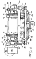
- a first driven pulley 7 and a second driven pulley 8 are supported rotatably at the first end 5 and are coaxial, while a driving pulley 9, keyed on the output shaft of a gearbox 9a with a corresponding motor 9b, and a guiding pulley 10 are rotatably supported at the second end 6 and are coaxial:
- the second driven pulley 8, the driving pulley 9 and the guiding pulley 10 have, on their lateral surface, an annular trapezoidal race 11 (Figure 2), while the first driven pulley 7 has two annular trapezoidal races 11 arranged side by side, as can be derived from Figure 1.
- a belt 12 is wound around pulleys 7, 8, 9 and 10, has a substantially trapezoidal cross-section, is closed in a loop and defines a first upper portion 13 and a second upper portion 14, which are active and parallel and on which the products are conveyed, and a first lower portion 15 and a second lower portion 16, which cross in an X-like arrangement.
- Pairs of brackets 17 are fixed to each one of the longitudinal members 3, at the sides of the first and second ends 5 and 6, and are extended vertically; each bracket has a portion 18 that is folded horizontally and is slotted for the locking, adjustable by means of screws, of longitudinal bars 19 that have a substantially H-shaped transverse cross-section and are designed for the sliding and support of the upper portions 13 and 14 of the belt 12.
- the longitudinal members 3 are provided with two rigidly coupled pairs of posts 20 and 21 for the adjustable support of cross-members 22 for support during product conveyance.
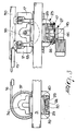
- the first end 5 and the second end 6 of the device are associated with respective translational motion means 23 ( Figure 3), which are suitable to adjust the mutual distance between the first upper portion 13 and the second upper portion 14.
- the translational motion means 23 comprise, at each end 5 and 6, a respective track 24 that lies transversely to the upper portions 13 and 14 and on which a first carriage 25 and a second carriage 26 are guided slidingly in opposite directions in order to rotatably support the respective pulleys 7, 8, 9 and 10: said carriages 25 and 26 are adjustable, with the aid of servo-assisted actuation means 27 ( Figures 2, 3 and 4), from a least open position, in which they are substantially mutually adjacent, to a fully open position, in which they are arranged at the opposite ends of the corresponding track 24.
- Each track 24, fixed transversely below the longitudinal members 3 by means of respective pairs of lower brackets 28, has a substantially U-shaped transverse cross-section, to the internal corners of which longitudinal inclined strips 29 are fixed (Figure 3); said strips are shaped like an elongated parallelepiped and have two respective mutually facing edges.
- the bottom 30 of the track 24 has a first slot 31 and a second slot 32, which are longitudinal and substantially rectangular and symmetrical with respect to the centerline of said track ( Figure 4).
- Each one of the carriages 25 and 26 is constituted by a substantially rectangular plate 33, on the upper face of which a respective pair of rotatable supports 34 is rigidly coupled; said supports have corresponding coaxial rolling bearings for a pivot 35 for the keying of a respective pulley.
- the second driven pulley 8 is keyed and associated with a first idler pulley 36 that is coaxial thereto and laterally adjacent thereto, while the driving pulley 9 and the guiding pulley 10 are respectively keyed and associated with a second idler pulley 37 and a third idler pulley 38 (Figure 1): said idler pulleys 36, 37 and 38 are suitable for the winding of additional trapezoidal belts for extending the conveyance line from either end 5 and 6.
- the lower face of the plate 33 provides a rotatable support for a plurality of pairs of wheels 39 having a vertical axis of rotation, which are provided with annular races 40 on the lateral surface ( Figure 3); said races engage in the respective edges of the strips 29 in order to slidingly guide the carriages 25 and 26 along the corresponding tracks 24. Furthermore, the plate 33 forms a downward extension 41 that is shaped substantially like a parallelepiped and is engaged respectively along the first slot 31 or along the second slot 32.
- Respective wings 42 for rotatably supporting guiding wheels 43 having a vertical axis for the lower portions 15 and 16 of the belt 12 are rigidly coupled by means of screws to each plate 33 on the two opposite sides that are parallel to the tracks 24, and are engaged in respective slots 43a that are parallel to the tracks 24 ( Figure 4).
- the guiding wheels 43 are suitable to ensure that the lower portions of the belt 15, 16 do not escape accidentally from the trapezoidal races 11 of the pulleys 7, 8, 9 and 10.
- the servo-assisted actuation means 27 are constituted by a gearmotor 44, which has a vertical axis that is fixed, under each track 24, on a respective quadrangular flange 45, which is supported at its corners by four blocks 46, which are bolted substantially at the centerline of said track 24 (see in this regard Figure 3, where only the gearmotor 44 related to the second end 6 has been shown for the sake of clarity).
- a crank 47 is keyed, substantially in its central portion, in the space formed between each track 24 and the respective flange 45 on the output shaft of the gearmotor 44; such crank 47 oscillates, on a horizontal plane that lies below the respective track 24, between two angular end positions.
- a first linkage 48 ( Figure 4) is articulated between the first end of the crank 47 and the downward extension 41 of the first carriage 25, which can slide along the first slot 31; a second linkage 49 is instead articulated between the second end of the crank 47 and the downward extension 41 of the second carriage 26, which can slide along the second slot 32 of the track 24.
- the angular end positions of the crank 47 therefore correspond respectively to the least open and fully open positions of the first and second carriages 25 and 26.
- the second end 6 of the device which can be a region of transition between two portions of a line having different peripheral speeds and as such can cause instabilities of the products as they advance, is provided with a first side wall 50 and with a second side wall 51 for the conveyed products ( Figures 1 and 2), which are arranged laterally and parallel to the respective first upper portion 13 and second upper portion 14 and are associated with means 52 for adjusting the distance of each side wall with respect to the corresponding upper portion.
- the side walls 50 and 51 are substantially constituted by elongated rectangular bars: the adjustment means 52 comprise first and second pairs of supports 53 and 54, which are parallel and are fixed, at the respective upper ends, at right angles to the corresponding side walls 50 and 51 and are pivoted, in the intermediate portion along parallel and longitudinal axes, to the chassis 2 of the device.
- the lower ends of one of the supports of each first and second pair 53, 54 are articulated, respectively by means of a first arm 55 and a second arm 56, to mutually opposite portions of the crank 47, said portions being located between the centerline of said crank and the points of articulation to the respective first and second linkages 48, 49 ( Figure 4).
- the adjustment means 52 are suitable to arrange the first and second side walls 50 and 51 at a distance from the respective first and second upper portions 13 and 14 that is smallest when the first and second carriages 25, 26 are in the least open position and is greatest when the first and second carriages are in the fully open position: said distance increases gradually in each intermediate open position.
- the operation of the belt-type conveyor according to the invention is as follows. Depending on the width of the products to be conveyed, the mutual distance between the first upper portion 13 and the second upper portion 14 is adjusted by acting on the servo-assisted actuation means 27: the synchronized rotation of the cranks 27 keyed on the respective gearmotors 14 causes, by means of the first and second linkages 48 and 49, the translational motion in opposite directions respectively of the first and second carriages 25 and 26 along the corresponding tracks 24 and the movement of the first and second side walls 50 and 51 respectively by means of the first and second arms 55 and 56. By then actuating the motor 9b, the driving pulley 10 and accordingly the belt 12 are turned, and the belt can transfer the products onto the corresponding upper portions 13 and 14.
- the belt-type conveyor is therefore capable of conveying effectively, with a single actuation motor, products having different widths and formats by means of simple and rapid actions on the servo-assisted actuation means 27, and is free from instabilities of the products caused by differences in the tangential speed of the upper portions 13 and 14 of the belts; said tangential speed is substantially independent of the diameter of the pulleys, of any imperfections in their machining, and of belt wear. Moreover, replacement of the worn belt is easy and fast, without disassembling mechanical parts.
Landscapes
- Engineering & Computer Science (AREA)
- Mechanical Engineering (AREA)
- Structure Of Belt Conveyors (AREA)
- Holders For Sensitive Materials And Originals (AREA)
- Advancing Webs (AREA)
Applications Claiming Priority (2)
| Application Number | Priority Date | Filing Date | Title |
|---|---|---|---|
| IT2001BO000772A ITBO20010772A1 (it) | 2001-12-21 | 2001-12-21 | Dispositivo di trasporto a cinghia a formato registrabile |
| ITBO20010772 | 2001-12-21 |
Publications (2)
| Publication Number | Publication Date |
|---|---|
| EP1321387A2 true EP1321387A2 (fr) | 2003-06-25 |
| EP1321387A3 EP1321387A3 (fr) | 2003-11-19 |
Family
ID=11439755
Family Applications (1)
| Application Number | Title | Priority Date | Filing Date |
|---|---|---|---|
| EP02025019A Withdrawn EP1321387A3 (fr) | 2001-12-21 | 2002-11-08 | Convoyeur à bande réglable |
Country Status (3)
| Country | Link |
|---|---|
| EP (1) | EP1321387A3 (fr) |
| CN (1) | CN1426940A (fr) |
| IT (1) | ITBO20010772A1 (fr) |
Cited By (7)
| Publication number | Priority date | Publication date | Assignee | Title |
|---|---|---|---|---|
| WO2007084261A3 (fr) * | 2005-12-16 | 2007-09-13 | Meadwestvaco Packaging Systems | Tremie a carton ajustable transversalement |
| DE102009060270A1 (de) * | 2009-12-23 | 2011-06-30 | Bizerba GmbH & Co. KG, 72336 | Mehrspurförderer |
| CN105668136A (zh) * | 2016-01-18 | 2016-06-15 | 张月妹 | 伺服电机驱动的皮带轮物料运输机 |
| CN105836391A (zh) * | 2016-06-13 | 2016-08-10 | 汤小牛 | 轻型短距离皮带输送设备 |
| CN105858089A (zh) * | 2016-06-13 | 2016-08-17 | 汤小牛 | 轻型短距离皮带输送机 |
| CN105905532A (zh) * | 2016-06-13 | 2016-08-31 | 汤小牛 | 轻型短距离皮带输送装置 |
| CN106219141A (zh) * | 2016-09-21 | 2016-12-14 | 深圳迈森自动化设备有限公司 | 一种锂电池喷涂输送装置 |
Families Citing this family (11)
| Publication number | Priority date | Publication date | Assignee | Title |
|---|---|---|---|---|
| WO2013079144A1 (fr) * | 2011-12-01 | 2013-06-06 | Bobst Mex Sa | Unite de convoyage de paquets pour une unite de transformation d'elements en plaque dans une ligne de production d'emballages |
| CN104590892A (zh) * | 2013-11-01 | 2015-05-06 | 浚丰太阳能(江苏)有限公司 | 一种光伏组件测试流水线 |
| CN103754558B (zh) * | 2014-01-27 | 2015-10-21 | 厦门烟草工业有限责任公司 | 一种条烟输送机装置 |
| CN105016026A (zh) * | 2015-06-10 | 2015-11-04 | 华南理工大学 | 一种大行程小体积直线移动平台 |
| CN105257806A (zh) * | 2015-11-11 | 2016-01-20 | 太原重工股份有限公司 | 滑轮装置 |
| DE102016103204A1 (de) * | 2016-02-24 | 2017-08-24 | Claas Selbstfahrende Erntemaschinen Gmbh | Antriebsanordnung für einen Mähdrescher |
| CN105562812B (zh) * | 2016-02-25 | 2018-03-02 | 江阴市北国包装设备有限公司 | 百叶端部间隔剪切机 |
| CN106185188B (zh) * | 2016-08-29 | 2018-10-26 | 南京优倍自动化系统有限公司 | 一种智能变轨运载机 |
| CN109017504A (zh) * | 2018-08-30 | 2018-12-18 | 英华达(上海)科技有限公司 | 一种输送机、自动导引运输车和自动化生产线 |
| CN113803412A (zh) * | 2021-09-16 | 2021-12-17 | 哈尔滨工程大学 | 摆动式同速同力四轴传动机构 |
| CN115475851B (zh) * | 2022-09-14 | 2025-03-14 | 四川嘉拓智能设备有限公司 | 一种单根线材穿带设备 |
Family Cites Families (5)
| Publication number | Priority date | Publication date | Assignee | Title |
|---|---|---|---|---|
| BE532889A (fr) * | ||||
| JPS5623112A (en) * | 1979-07-31 | 1981-03-04 | Natl House Ind Co Ltd | Locating device |
| JPS6151407A (ja) * | 1984-08-20 | 1986-03-13 | Matsushita Electric Ind Co Ltd | コンベア装置 |
| SE447983B (sv) * | 1985-02-14 | 1987-01-12 | Rolf I Johansson | Synkronisering av band hos bandtransportorer |
| CA2111040C (fr) * | 1993-04-23 | 1999-04-13 | David J. Waterman | Trieuse ponderale a plateau variable |
-
2001
- 2001-12-21 IT IT2001BO000772A patent/ITBO20010772A1/it unknown
-
2002
- 2002-11-08 EP EP02025019A patent/EP1321387A3/fr not_active Withdrawn
- 2002-12-20 CN CN02157478A patent/CN1426940A/zh active Pending
Cited By (7)
| Publication number | Priority date | Publication date | Assignee | Title |
|---|---|---|---|---|
| WO2007084261A3 (fr) * | 2005-12-16 | 2007-09-13 | Meadwestvaco Packaging Systems | Tremie a carton ajustable transversalement |
| DE102009060270A1 (de) * | 2009-12-23 | 2011-06-30 | Bizerba GmbH & Co. KG, 72336 | Mehrspurförderer |
| CN105668136A (zh) * | 2016-01-18 | 2016-06-15 | 张月妹 | 伺服电机驱动的皮带轮物料运输机 |
| CN105836391A (zh) * | 2016-06-13 | 2016-08-10 | 汤小牛 | 轻型短距离皮带输送设备 |
| CN105858089A (zh) * | 2016-06-13 | 2016-08-17 | 汤小牛 | 轻型短距离皮带输送机 |
| CN105905532A (zh) * | 2016-06-13 | 2016-08-31 | 汤小牛 | 轻型短距离皮带输送装置 |
| CN106219141A (zh) * | 2016-09-21 | 2016-12-14 | 深圳迈森自动化设备有限公司 | 一种锂电池喷涂输送装置 |
Also Published As
| Publication number | Publication date |
|---|---|
| ITBO20010772A1 (it) | 2003-06-21 |
| CN1426940A (zh) | 2003-07-02 |
| ITBO20010772A0 (it) | 2001-12-21 |
| EP1321387A3 (fr) | 2003-11-19 |
Similar Documents
| Publication | Publication Date | Title |
|---|---|---|
| EP1321387A2 (fr) | Convoyeur à bande réglable | |
| CN102958819B (zh) | 带式输送系统 | |
| US7222723B2 (en) | Apparatus for diverting a stream of articles | |
| US3983988A (en) | Conveyor diverter | |
| US8955664B2 (en) | Belt conveyor system | |
| EP2225943B1 (fr) | Procédé et dispositif pour laminer de la pâte alimentaire | |
| US6508153B1 (en) | Conveyor product transfer apparatus and method | |
| US9022200B2 (en) | Accumulation conveyor | |
| EP3119705A1 (fr) | Convoyeur destiné à transporter des produits dans une direction verticale | |
| EP2225942B1 (fr) | Dispositif pour étendre une pâte alimentaire | |
| EP1360902B1 (fr) | Appareil destine a etendre au rouleau une pate alimentaire | |
| US11400492B2 (en) | Sorting device | |
| CN110902278A (zh) | 一种自动化生产线用传送装置 | |
| EP1818293A1 (fr) | Transporteur | |
| EP1321390A1 (fr) | Méchanisme d'entrainement à poulie reglable | |
| JP3617919B2 (ja) | プレス材搬送装置 | |
| CN212374224U (zh) | 传动组件、传动装置和流水线 | |
| KR101128350B1 (ko) | 컨베이어 설비 | |
| CN223279960U (zh) | 一种旋转输送线 | |
| CN206013655U (zh) | 一种万向输送装置 | |
| CN220244435U (zh) | 一种传送带对接分流机构 | |
| US4090603A (en) | Collecting arrangement | |
| JPH085143Y2 (ja) | 高速仕分機 | |
| CN219357695U (zh) | 一种分流输送装置 | |
| CN110239928A (zh) | 一种智能带输送分道机 |
Legal Events
| Date | Code | Title | Description |
|---|---|---|---|
| PUAI | Public reference made under article 153(3) epc to a published international application that has entered the european phase |
Free format text: ORIGINAL CODE: 0009012 |
|
| AK | Designated contracting states |
Designated state(s): AT BE BG CH CY CZ DE DK EE ES FI FR GB GR IE IT LI LU MC NL PT SE SK TR |
|
| AX | Request for extension of the european patent |
Extension state: AL LT LV MK RO SI |
|
| PUAL | Search report despatched |
Free format text: ORIGINAL CODE: 0009013 |
|
| AK | Designated contracting states |
Kind code of ref document: A3 Designated state(s): AT BE BG CH CY CZ DE DK EE ES FI FR GB GR IE IT LI LU MC NL PT SE SK TR |
|
| AX | Request for extension of the european patent |
Extension state: AL LT LV MK RO SI |
|
| STAA | Information on the status of an ep patent application or granted ep patent |
Free format text: STATUS: THE APPLICATION HAS BEEN WITHDRAWN |
|
| 18W | Application withdrawn |
Effective date: 20040429 |