EP1321417B1 - Gaine d'ascenseur et méthode pour ériger la gaine d'ascenseur - Google Patents
Gaine d'ascenseur et méthode pour ériger la gaine d'ascenseur Download PDFInfo
- Publication number
- EP1321417B1 EP1321417B1 EP02027351A EP02027351A EP1321417B1 EP 1321417 B1 EP1321417 B1 EP 1321417B1 EP 02027351 A EP02027351 A EP 02027351A EP 02027351 A EP02027351 A EP 02027351A EP 1321417 B1 EP1321417 B1 EP 1321417B1
- Authority
- EP
- European Patent Office
- Prior art keywords
- travel path
- lift shaft
- modular
- path element
- lift
- Prior art date
- Legal status (The legal status is an assumption and is not a legal conclusion. Google has not performed a legal analysis and makes no representation as to the accuracy of the status listed.)
- Expired - Lifetime
Links
Images




Classifications
-
- E—FIXED CONSTRUCTIONS
- E04—BUILDING
- E04F—FINISHING WORK ON BUILDINGS, e.g. STAIRS, FLOORS
- E04F17/00—Vertical ducts; Channels, e.g. for drainage
- E04F17/005—Lift shafts
Definitions
- the present invention relates to an elevator shaft according to the preamble of patent claim 1 and to a method for constructing a hoistway according to the preamble of patent claim 13.
- a self-supporting cable lift is known in which the leadership of the cabins and the counterweights on the shaft door front is arranged.
- a statically self-supporting integrated front structure is provided, which extends from the shaft floor to the shaft ceiling and at the same time forms a partition wall between the vestibule and the shaft.
- the structure is a steel construction.
- the integrated front structure has at least two shaft door modules arranged vertically between a lower buffer module and an upper drive module.
- the integrated front structure incorporates two continuous, modular, vertical, hollow pillars, called door pillars, because they define a gap in which the shaft doors are located. These hollow door pillars carry the counterweights inside.
- a frame with guide rails for guiding the cabin is attached on the right and left of the back of the door pillars.
- This frame forms with the door front a U-shaped structure.
- another frame with rails for guiding the cabin is welded at right angles to the door front.
- the landing door modules may, if different storey heights exist, comprise a standard hoistway door unit and an order-specific matching unit, which are clamped in a vertical axis by means of pins mounted on the guide rail frame to reach the predetermined height of the hoistway door module.
- the built-in components of the drive module are accessible from the vestibule via a flap.
- the traction sheaves are each provided with its own drive unit.
- the hollow pillars of the hoistway door unit may be made of various materials such as steel, aluminum, concrete, plastic and have different shapes.
- a concrete structure which serves as an elevator shaft with two guide walls, as well as a front wall and a rear wall.
- ribs are designed with multiple guide surfaces, which serve as a guide for the elevator car.
- These ribs are homogeneously and continuously connected to the wall parts. Parallel to these ribs, similar guide members are provided to provide extra security to the wire or roped counterweight for safety reasons.
- the side walls are each provided on two opposite ends, top and bottom, with centerings.
- the invention makes it possible to significantly reduce the expense of a structural type for such systems.
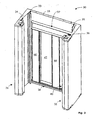
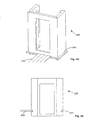
- the modular roadway elements 10 and 20 according to FIGS. 1 and 2 basically have three walls 1, 2, 3 and an at least approximately C-shaped cross section or ground plan.
- These C-shaped track members 10 and 20 are preferably constructed to form prefabricated lane and door front modules, and each include two integral car guides or lanes 11, 12 (FIG. 1) and 21, 22 (FIG. 2).
- the corners or corner edges 14, 15 are formed at right angles, but they can also be rounded or have other architecturally and technically useful forms. They also do not necessarily have to be symmetrical, as shown in FIGS. 1 and 2.
- the surfaces 16, 17 of the inner sides of the C-shaped track member may be parallel or, as shown in Fig. 1, on the shaft inside an inner corner angle ⁇ form, for example, greater than 90 degrees, the walls 1, 2 with increasing distance from the wall 3 can become thinner.
- the modular lane members 10 and 20 are prefabricated concrete modules (eg, cast concrete), where the lane members 10 and 20 may be provided with channels 18 or other recesses for integrated wiring.
- the roadways 11, 12 (FIG. 1) and 21, 22 (FIG. 2) can be provided with a continuous cavity 19, for example for a cable for mutually clamping a plurality of mutually stationary roadway elements 10, 20. Due to the mutual bracing, the stability of an elevator shaft consisting of a plurality of modular roadway elements 10, 20 can be improved.
- Concrete integrated guides 33, 34 and 35, 36 for balancing weights and guides integrated into the concrete 37, 38 for shaft doors are formed directly in the concrete, or cast as metal guides in the concrete, for example.
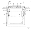
- Fig. 4 shows a top view of the hoistway, which may be peripherally terminated by another C-shaped structure or module 39 where an elevator car 40 is housed with doors 41, 42, 43, 44 forming a door system with sliding door leaves.
- the module 39 is designed statically non-supporting.
- a support 45 with rollers 93, 94, 95, 96 for guiding the elevator car is fixed at the top and bottom.
- four optionally preassembled shaft doors 46, 47, 48, 49 are shown, which can be mounted in the guides 37, 38.
- the balance weight guides 33 to 36 laterally, ie left and / or right to the at least approximately parallel or preferably an inner corner angle ⁇ > 90 ° forming sides 16, 17 (Fig. 1) of the C-shaped track element 30 and be arranged within the shaft wall projection.
- the module 39 may have a supporting function in the building, but without bearing the hoistway and its elements.
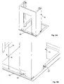
- FIGS. 5A and 5B Shown in FIGS. 5A and 5B is a roadway element 70 resting on a prefabricated well pit 60.
- This pit pit 60 is poured into the building floor panel of the building and is therefore later practically invisible from outside the elevator shaft.
- the tray 60 serves as a formwork during the casting of the building floor panel.
- a possible embodiment of a well pit 60 is shown in FIGS. 5A, 5B and 7 and represents a base module introduced by a builder as a pit.
- the tub 60 has a bottom 64.
- the term well may also be used to subsume a trough with a bottom having an opening or even a bottomless frame.
- the building floor slab is produced on a ground floor (e.g., the excavation floor), whereby the tub 60 can be poured.
- a first prefabricated delivered to the site for example, C-shaped roadway element 70 can be introduced, after which further roadway elements 20 (Fig. 2) are stacked and, with the building growing, mounted.
- This work can be carried out at least in part by a master builder.
- the stacked and supported on the building floor panel roadway elements form an elevator support structure, which can carry a top module (see, for example, Figures 8A and 8B) and stairwell pedestals.
- the roadway elements are preferably dimensioned from the statics forth so that they are able to absorb the vertical forces in the elevator shaft. In particular, these vertical rams are the own weight of the elevator shaft and the forces that occur during operation of the elevator.
- an installation example for the installation of a pit pit 60 is given.
- a pit a provided with a thin, horizontal mortar bed, taking into account the exact altitude.
- the pit tray 60 is inserted and pushed on this mortar bed in the correct position.
- the pit pit 60 can be filled with water so that it does not shift when pouring the building floor plate.
- Concrete is then poured into the excavation around the well pit to create the building floor slab.
- the first roadway element 70 is placed, as indicated schematically in Figures 6 and 7 by arrows.
- a thin layer of mortar can be applied.
- the roadway element 70 is positioned by means of a centering & positioning pin 71.
- the exact location in the horizontal plane is adjusted by rotation about a vertical axis 72.
- the roadway element is lowered into the mortar layer.
- the position of the roadway element can be adjusted.
- the mortar layer at least partially carries the weight of all roadway elements.
- the next following track element is preferably aligned after casting the first concrete deck (1st floor slab) with two centering & positioning bolts with respect to the underlying track element.
- the tray 60 has, as discussed, at least one integrated centering & positioning pin 71.
- the tray has screw holes 73 into which fixing screws 74 can be screwed to secure the track member 70 to the tray 60.
- the tub 60 an all-round Abdichtflansch 63 to seal from groundwater.
- the trough 60 may also be provided with tabs 75 which anchor the trough in the building floor panel. However, it does not have to be supportive of the elevator structure; the forces are preferably passed directly through the mortar layer in the building floor plate.
- Trained as a tray 60 base module has a low weight and a small volume for transport and installation and brings a drastic reduction in construction time and construction costs, in particular, no special hoist for larger loads is required.
- a basic module simultaneously fulfills building and elevator functions.
- the shaft pit had to be cast in concrete at the location of the lift shaft to be built by step by step, the corresponding shuttering made of wood were constructed. This process was very labor intensive and expensive. These steps are eliminated when using a trough 60 according to the invention.
- the trough 60 preferably consists of a CF composite.
- the tub 60 has a weight of less than 100kg.
- the uppermost element of the elevator shaft which is also called top module 80, has at least one drive 81 and a plurality of rollers according to FIGS. 8A and 8B, for example the rollers 91, 92, 97, 98 for the cabin-side runners 82 and / or for the rollers counterweight strand 83 of the support and drive cables.
- the top module 80 to which the elevator car 40 and at least one counterweight (not shown here) hang indirectly (see FIG. 8B), may be a kind of cover 86 which extends from a flat roof 89 (building ceiling). is introduced ago.
- a drive 81 and pulleys 91, 92, 97, 98 are attached, and it has seals 87 against the building and at least one vent slot 88.
- the top module 80 preferably rests on an upper roadway element 100.
- the top module 80 is preferably a prefabricated concrete element.
- This top module 80 with integrated elevator and construction functions which is positioned and supported on the uppermost lane and door front module 100, may be factory pre-assembled with suspension and deflection rollers (eg, rollers 91, 92, 97, 98) with a factory pre-assembled one Drive unit 81 and / or be provided with integrated building interfaces or building interfaces for sealing and insulating the top building ceiling 89.
- the top module 80 can be used as an interior formwork for casting the building ceiling 89.
- top module 80 mounted on the shaft head and serving as a ceiling connection is cost-effective in terms of transport and assembly, affords great safety during elevator installation, can be used as packaging for the elevator components, for example the rollers and the drive, and also leads to minor on-site Costs of shaft head construction.
- the top module 80 may be configured such that it can be used as a weather protection during an installation phase.
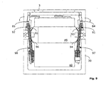
- one roller 91 or 92 each is arranged for the two ropes 83 (FIG. 8B) carrying the counterweights 84 and 85, respectively, in such a way that the projection of each hanging one Rope 83 at least approximately through the center of gravity of the corresponding counterweight 84 and 85 runs.
- the four rollers 93, 94, 95, 96 are preferably formed by the trapezoidally shaped cabin guides 11, 12 (FIG. 1), or 21, 22 (FIG. 2), or 31, 33 (FIG. 3) of the respective modular one Track element led.
- the preferably C-shaped roadway elements 10 (FIG. 1), 20 (FIG. 2), 70 (FIG. 6) and 100 (FIG. 8B) can also be used to carry stairwell platforms, even if the complementary module 39 (FIG. Fig. 4 or Fig. 9) is omitted, for example, to form a respect to design and carrying forces free rear shaft wall area as a design freedom for architects.
- the C-shaped roadway elements 10, 20, 70 and 100 can then be "built in” and "outside” on the facade of a building, or built into a facade niche or attachable.
- the modular C-shaped roadway elements 10, 20, 70 and 100 according to the invention can be designed for direct reception of functional elements (eg functional elements of the door mechanism). It does not necessarily require special metal frames or metal profiles.
- the roadway elements 10, 20, 70 and 100 may have so-called gypsum edges to allow easier plastering of the shaft outer walls. Their modular design eliminates the need to compensate for building tolerances.
- the modular roadway elements 10, 20, 70 and 100 may have special recesses or attachment means have for direct, frameless fastening of the door mechanism.
- the modular elevator shaft according to the invention proves to be particularly advantageous in that no additional door frame is required for supporting or supporting doors, or for cleaning and accurate closure or for fire protection requirements.
- the individual modules or elements have only a low weight and a small volume, which not only brings advantages in transport and installation with it, but even allows the construction of the elevator shaft by the contractor construction company in the absence of elevator experts at the site without doing To require a specific lifting and lifting gear, because construction and elevator functions are met with the same elements or modules, even the display and controls may be pre-assembled.
- the rollers 93, 94, 95 and 96 are guided by the trapezoidal roadways 11 and 12 (FIG. 1), for example.
- the trapezoidal roadways 11 and 12 (FIG. 1) are preferably cast from concrete. Since these lanes serve only to guide the cabin 40, they are unproblematic from a static point of view. It is possible to provide relatively thin walls 16 and 17 ( Figure 1), which, however, should not be used for fastening or as supporting structures. Also, one should try in the design of the entire elevator shaft and the individual roadway elements to avoid sound bridges to allow good sound insulation.
- the horizontal Road loads due to eccentric loading of the elevator car 40 can reach relatively high levels. These horizontal loads are - even with thin walls 16 and 17 ( Figure 1) - unproblematic because they are collected on each floor by the floors.
- the connections between the roadway elements and the floor slabs can be realized either as rigid concrete / concrete joints or in the form of elastic sound insulation.
- the counterweight guide for example in the form of the rails 33 and 35, could also be arranged at least partially on the door front wall 3.
- the carrier 45 of the cab 40 ( Figure 9) is guided directly over the four upper guide rollers 93 to 95 and, for example, via four further lower rollers of a lower carrier not visible in the figures, for example along the concrete tracks 21, 22 ( Figure 2) ,
- the trapezoidal design of the roadways 21, 22 results in four elongated guide planes 24, 25 and 26, 27 in Fig. 2, which extend vertically in the elevator shaft.
- the intermediate levels 28 and 29 are not used to guide the elevator car 40, but may optionally be used for other functions. Due to the selected trapezoidal design of the roadways 21, 22, the guidance of the car 40 is very stable and also usable, for example, to absorb vertical forces.
- the guide geometry is very accurate, as the bump points and track distance are shaped.
- FIG. 10 The ends of a roadway 21, 22 (FIGS. 11, 12) of a roadway element are preferably provided with a coupling element 101 according to FIG. 10 cast directly in the concrete.
- Figures 11 and 12 show coupling pieces 110 and 120 at the ends of two abutting roadway elements. These coupling pieces 110 and 120 comprise a centering pin 121 (FIG. 12) and a centering hole 111 (FIG. 11), whereby they are automatically aligned with one another during assembly of the elevator shaft.
- the coupling pieces 101 are provided in the example shown with bolted anchors 131, 132 and 133, 134 of FIG. 13 and 14 to keep them anchored in the concrete after pouring.
- the surfaces 112, 113, 114 and 122, 123, 124 have the same polygonal cross-sectional shape, such as the trapezoidal lanes 11 and 12 of FIG. 1 or 21 and 22 of FIG. 2.
- the coupling pieces 110 and 120 are made of metal and can thus also serve as edge protection.
- the treads 11, 12, 21, 22 should have no grooves, heels or other bumps to bumps or
- rollers 93, 94, 95, 96 To avoid vibrations that could otherwise be transmitted via the rollers 93, 94, 95, 96 to the car 40.
- the coupling pieces 101 (FIG. 10), 110, 120 (FIGS. 11, 12) are inserted into the casting mold prior to the casting of the roadway elements. This results in ideally even transitions from the concrete cast guide treads to the coupling pieces. Since superimposed coupling pieces of adjacent roadway elements are mutually precisely centered, perfectly aligned, heel-free roadways result in the assembled state.
- the coupling pieces 101 preferably each have at least one recess 104 and / or a (threaded) bore 105, 106, which serve for the mutual fixation of two mutually-facing roadway elements, for example with connecting straps.
- (threaded) holes 107, 108 may be present with which a rotation or displacement of the inserted when casting the roadway elements in the mold coupling pieces is prevented.
- the roadway elements 10, 20, 30, 70 and 100 are preferably provided with a continuous cavity 19 and the coupling pieces 101 with openings 109 in order to be able to pass through such cavities 19 and openings 109, for example, at least one cable.
- the roadway elements 10, 20, 30, 70 and 100 are preferably provided with roadways 11, 12 and 21, 22 or 31, 32, which have an at least approximately trapezoidal cross section, wherein the coupling pieces 101 may be formed plate-shaped with the same trapezoidal cross-section.
- the sloping trapezoid sides of the carriageways may also serve as guides for rollers 93, 94, 95, 96 located on a support 45 fixed to the elevator car 40.
- the rollers 93, 94, 95, 96 may also be otherwise connected to the elevator car 40.
- FIG. 15 shows a modular roadway element 140, which has a type of circumferential ledge 141 in the lower region.
- This ledge 141 may, for example, support a formwork 142 for the casting of a floor slab, as illustrated in FIG.
- Another variant is shown in the sectional view in FIG. 16.
- the roadway element 150 has a recess 151 which can serve as a means for receiving a formwork 152, as indicated on the left side of the figure. Under certain circumstances, the means 141 and 151 can also carry the floor slab directly.
- the elevator shaft may be formed with prefabricated modular roadway elements (e.g., the roadway elements 10, 20) having an at least approximately C-shaped cross-section.
- a preferably modular elevator shaft may comprise roadways 11, 12 or 21, 22 or 31, 32, which have an at least approximately trapezoidal cross-section, wherein the sloping trapezoidal sides of the roadways as guide for rollers 93, 94, 95, 96, which are located on at least one support 45, which is attached to the elevator car 40.
- a modular elevator shaft can be formed with at least two prefabricated modular roadway elements (eg from the roadway elements 10, 20), which include roadways 11, 12, 21, 22 for the elevator car 40, such that at least at the upper end a lower lane of a lane element, a coupling piece 120 (FIG. 12) is fixedly arranged, and that at least at the lower end of an upper lane of a next lane element another coupling piece 110 (FIG. 11) is fixed, wherein both coupling pieces 110, 120 are configured in order to form an aligned transition between these two lanes at least in a region provided for guiding the elevator car 40.
- a coupling piece 120 FIG. 12
- both coupling pieces 110, 120 are configured in order to form an aligned transition between these two lanes at least in a region provided for guiding the elevator car 40.
- the elevator shaft can at least partially rest on a concrete floor slab in which a trough 60 is inserted, which serves as shuttering during the casting of the building floor slab.
- the shaft head of a hoistway can be designed as a modular prefabricated top module 80 made of concrete.
- elevators have been illustrated in which steel cords running over rollers carry the cab 40 and the counterweight (s).
- hydraulic drives can readily be used.
- straps can be used instead of ropes.
- inventive embodiments of such a hoistway prove to be particularly cost-effective in the production in the factory and for transport and installation. They provide increased safety during the lift assembly and possibly allow the use of a top module as a "packaging" of the elevator components, such as units with rollers and drive.
Landscapes
- Engineering & Computer Science (AREA)
- Architecture (AREA)
- Civil Engineering (AREA)
- Structural Engineering (AREA)
- Types And Forms Of Lifts (AREA)
- Lift-Guide Devices, And Elevator Ropes And Cables (AREA)
Claims (13)
- Gaine d'ascenseur à construction modulaire, qui comprend au moins un élément modulaire préfabriqué à glissières (10 ; 20 ; 30 ; 70 ; 100) qui est formé par les deux parois latérales (1, 2) et une troisième paroi (3) disposée entre celles-ci, de sorte que l'élément à glissières (10 ; 20 ; 30 ; 70 ; 100) présente une section transversale au moins approximativement en C et les deux parois latérales (1, 2) comportent chacune une glissière intégrée (11, 12 ; 21, 22) pour le guidage de la cabine d'ascenseur (40),
caractérisée en ce que l'élément à glissières (10 ; 20 ; 30 ; 70 ; 100) est conçu d'une seule pièce et en ce que la troisième paroi (3) est pourvue d'une ouverture de porte (13 ; 23). - Gaine d'ascenseur selon la revendication 1, caractérisée en ce que l'élément modulaire à glissières (10 ; 20 ; 30) est préfabriqué d'une seule pièce sous la forme d'une structure en béton et comporte des guidages de cabine (31, 32) intégrés dans la structure en béton et/ou des guidages (33, 34 ; 35, 36) intégrés dans la structure en béton pour les contrepoids et/ou des guidages (37, 38) intégrés dans la structure en béton, dans la zone de l'ouverture de porte (13 ; 23), pour les portes palières.
- Gaine d'ascenseur selon la revendication 2, caractérisée en ce que les guidages de cabine intégrés (31, 32) et les guidages (33, 34 ; 35, 36) pour les contrepoids se trouvent tous sur les surfaces intérieures (16, 17) des deux parois latérales (1, 2) de l'élément modulaire à glissières (10 ; 20 ; 30).
- Gaine d'ascenseur selon la revendication 2 ou 3, caractérisée en ce que les surfaces intérieures (16, 17) des parois latérales (1, 2) de l'élément modulaire à glissières (10 ; 20 ; 30) forment, au moins dans la zone où se trouvent les guidages (33, 34 ; 35, 36) pour les contrepoids de la cabine d'ascenseur (40), un angle intérieur (α) qui est supérieur à 90 degrés, et l'épaisseur des parois latérales (1, 2) diminue ainsi au fur et à mesure qu'on s'éloigne de la troisième paroi (3).
- Gaine d'ascenseur selon l'une des revendications 1 à 4, caractérisée en ce que l'élément modulaire à glissières (10 ; 20 ; 30) est pourvu de conduits (18) qui sont parallèles aux guidages de cabine, de préférence pour un câblage intégré.
- Gaine d'ascenseur selon l'une des revendications 1 à 5, caractérisée en ce qu'elle comprend plusieurs éléments modulaires à glissières (10 ; 20 ; 30) superposés, ces éléments modulaires à glissières (10 ; 20 ; 30) étant pourvus d'une cavité continue (19), de préférence pour un câble destiné à relier avec une contrainte les éléments (10 ; 20 ; 30).
- Gaine d'ascenseur selon l'une des revendications 1 à 6, caractérisée en ce que l'élément modulaire à glissières (10 ; 20 ; 30) est pourvu de glissières (11, 12 ; 21, 22) qui présentent une section transversale au moins approximativement trapézoïdale, et en ce que les glissières (11, 12 ; 21, 22) présentent des côtés de trapèze inclinés (24, 25, 26, 27) qui servent de guidage pour des galets (93, 94, 95, 96) reliés à la cabine d'ascenseur (40).
- Gaine d'ascenseur selon l'une des revendications 1 à 7, caractérisée en ce que l'élément modulaire à glissières (10 ; 20 ; 30 ; 70 ; 100) est dimensionné, d'un point de vue statique, de manière à servir de structure porteuse afin de recevoir les forces verticales de la gaine d'ascenseur, en particulier le poids propre de celle-ci, et les forces qui apparaissent lors du fonctionnement de l'ascenseur.
- Gaine d'ascenseur selon l'une des revendications 1 à 8, caractérisée en ce que l'élément modulaire à glissières (10 ; 20 ; 30 ; 70 ; 100) est dimensionné pour pouvoir porter un palier d'escalier et/ou un module supérieur (80).
- Gaine d'ascenseur selon l'une des revendications 1 à 9, caractérisée en ce qu'un module (39) est prévu en face de la troisième paroi centrale (3) afin de fermer la gaine, le module (39) étant conçu de préférence comme un élément non porteur de la gaine.
- Gaine d'ascenseur selon l'une des revendications 1 à 10, caractérisée en ce que l'élément modulaire à glissières (10 ; 20 ; 30) est équipé à l'usine de portes palières intégrées (46, 47, 48, 49).
- Gaine d'ascenseur selon l'une des revendications 1 à 11, caractérisée en ce que l'un au moins des éléments modulaires à glissières (140 ; 150) comporte des moyens (141 ; 151) qui sont aptes à supporter un coffrage (142 ; 152) pour le coulage d'un plafond.
- Procédé pour ériger une gaine d'ascenseur selon l'une des revendications 1 à 11, caractérisé- en ce qu'on place un premier élément modulaire préfabriqué à glissières (10) sur une plaque de fondation de bâtiment fabriquée à l'endroit d'un bâtiment à construire,- en ce qu'on oriente horizontalement et verticalement l'élément modulaire préfabriqué à glissières (10), et- en ce qu'on positionne ensuite au moins un autre élément modulaire à glissières (20) sur le premier élément modulaire préfabriqué à glissières (10), la gaine d'ascenseur étant montée au fur et à mesure de la progression de la construction.
Priority Applications (1)
| Application Number | Priority Date | Filing Date | Title |
|---|---|---|---|
| EP02027351A EP1321417B1 (fr) | 2001-12-21 | 2002-12-07 | Gaine d'ascenseur et méthode pour ériger la gaine d'ascenseur |
Applications Claiming Priority (3)
| Application Number | Priority Date | Filing Date | Title |
|---|---|---|---|
| EP01811255 | 2001-12-21 | ||
| EP01811255 | 2001-12-21 | ||
| EP02027351A EP1321417B1 (fr) | 2001-12-21 | 2002-12-07 | Gaine d'ascenseur et méthode pour ériger la gaine d'ascenseur |
Publications (2)
| Publication Number | Publication Date |
|---|---|
| EP1321417A1 EP1321417A1 (fr) | 2003-06-25 |
| EP1321417B1 true EP1321417B1 (fr) | 2007-07-11 |
Family
ID=38289100
Family Applications (1)
| Application Number | Title | Priority Date | Filing Date |
|---|---|---|---|
| EP02027351A Expired - Lifetime EP1321417B1 (fr) | 2001-12-21 | 2002-12-07 | Gaine d'ascenseur et méthode pour ériger la gaine d'ascenseur |
Country Status (5)
| Country | Link |
|---|---|
| EP (1) | EP1321417B1 (fr) |
| AT (1) | ATE366707T1 (fr) |
| DE (1) | DE50210450D1 (fr) |
| ES (1) | ES2290236T3 (fr) |
| PT (1) | PT1321417E (fr) |
Cited By (1)
| Publication number | Priority date | Publication date | Assignee | Title |
|---|---|---|---|---|
| CN109537849A (zh) * | 2018-11-16 | 2019-03-29 | 立达博仕电梯(苏州)有限公司 | 一种加装电梯井道支撑架 |
Families Citing this family (8)
| Publication number | Priority date | Publication date | Assignee | Title |
|---|---|---|---|---|
| GB2473026A (en) * | 2009-08-26 | 2011-03-02 | Waycon Precast Ltd | Lift shaft assembly comprising pre-fabricated concrete sections |
| US8800725B2 (en) * | 2011-01-05 | 2014-08-12 | Dominick J. Alois | Elevator liner apparatus and utilization method thereof |
| AU2021107156A4 (en) * | 2020-11-10 | 2021-12-02 | Iavilaer Pty Ltd | Construction of a lift shaft or stair core |
| CN114592708A (zh) * | 2021-04-29 | 2022-06-07 | 深圳市凌盛电子有限公司 | 小高层建筑电梯改建过程的无遮挡式防掉落外墙施工组件 |
| EP4083344A1 (fr) * | 2021-04-30 | 2022-11-02 | Manfred Greschbach | Élément de cage d'un ascenseur ainsi que procédé de fabrication d'une cage d'ascenseur |
| CN116816033B (zh) * | 2022-03-17 | 2025-07-15 | 联知(浙江)实业有限公司 | 相邻两根烟管在建筑物上的安装方法及建筑物 |
| CN115095106B (zh) * | 2022-05-31 | 2024-01-30 | 上海宝冶集团有限公司 | 一种电梯井道结构及其施工方法 |
| CN114922385A (zh) * | 2022-07-18 | 2022-08-19 | 山东天齐置业集团股份有限公司 | 柱式电梯导轨固定结构及施工方法 |
Family Cites Families (6)
| Publication number | Priority date | Publication date | Assignee | Title |
|---|---|---|---|---|
| CH525833A (de) * | 1969-11-11 | 1972-07-31 | Hladnik Damjan | Aufzugsschacht |
| DE2210631A1 (de) * | 1972-03-06 | 1973-09-20 | Haushahn Fa C | Aufzug fuer hochbauten |
| GB1459537A (en) * | 1974-11-21 | 1976-12-22 | Maquinaria Y Utiles Para La Co | Elevator |
| DE2755267A1 (de) * | 1977-12-12 | 1979-06-13 | Dieter Brodthage | Vorrichtung zur herstellung von aufzugschachtbausteinen |
| AU7518498A (en) * | 1998-06-10 | 1999-12-30 | Zund Ag | Elevator guiding device |
| DE20105144U1 (de) * | 2001-03-24 | 2001-07-12 | Müller, Wolfgang T., 78315 Radolfzell | Selbsttragender Seilaufzug mit Kabinen- und Gegengewichtsführung in der Schachttürfront |
-
2002
- 2002-12-07 PT PT02027351T patent/PT1321417E/pt unknown
- 2002-12-07 ES ES02027351T patent/ES2290236T3/es not_active Expired - Lifetime
- 2002-12-07 DE DE50210450T patent/DE50210450D1/de not_active Expired - Lifetime
- 2002-12-07 AT AT02027351T patent/ATE366707T1/de not_active IP Right Cessation
- 2002-12-07 EP EP02027351A patent/EP1321417B1/fr not_active Expired - Lifetime
Non-Patent Citations (1)
| Title |
|---|
| None * |
Cited By (2)
| Publication number | Priority date | Publication date | Assignee | Title |
|---|---|---|---|---|
| CN109537849A (zh) * | 2018-11-16 | 2019-03-29 | 立达博仕电梯(苏州)有限公司 | 一种加装电梯井道支撑架 |
| CN109537849B (zh) * | 2018-11-16 | 2020-10-20 | 立达博仕电梯(苏州)有限公司 | 一种加装电梯井道支撑架 |
Also Published As
| Publication number | Publication date |
|---|---|
| ATE366707T1 (de) | 2007-08-15 |
| PT1321417E (pt) | 2007-09-12 |
| EP1321417A1 (fr) | 2003-06-25 |
| ES2290236T3 (es) | 2008-02-16 |
| DE50210450D1 (de) | 2007-08-23 |
Similar Documents
| Publication | Publication Date | Title |
|---|---|---|
| EP3899167B1 (fr) | Dispositif de construction pourvu de coffrage grimpant et système d'ascenseur | |
| EP2356056B1 (fr) | Charpente de puits pour une installation d'ascenseur | |
| EP3315448B1 (fr) | Installation d'ascenseur | |
| EP3712355B1 (fr) | Procédé d'équipement ultérieur d'un bâtiment d'une installation d'ascenseur et ensemble de composants destiné à la mise en uvre du procédé | |
| EP1321417B1 (fr) | Gaine d'ascenseur et méthode pour ériger la gaine d'ascenseur | |
| DE20002775U1 (de) | Aufzugs-Treppenhausmodul mit variablen Abmessungen | |
| EP1321418B1 (fr) | Gaine d'ascenseur | |
| EP1321419A1 (fr) | Module d'entrainement pour une cage d'ascenseur modulaire | |
| DE4300823A1 (de) | Gelaender zur Befestigung an seitlichen Begrenzungswänden | |
| DE19814639A1 (de) | Aufzugsanlage und Verfahren zu deren Anbindung an das Treppenhaus eines bestehenden, in Plattenbauweise hergestellten Gebäudes | |
| EP1321420A1 (fr) | Module de cage pour ascenseur | |
| EP1321421A1 (fr) | Socle en forme de bac qui constitue le module de base pour une cage d'ascenseur | |
| DE20300662U1 (de) | Baukonstruktion zur nachträglichen Anbindung eines Außenaufzuges an ein Treppenhaus eines mehrgeschossigen Gebäudes | |
| EP1894876A1 (fr) | Dispositif d'élévation doté d'une cabine et d'un contrepoids et procédé destiné à la disposition d'une installation d'élévation | |
| DE19954649C2 (de) | Verfahren und Vorrichtung zur nachträglichen Montage eines vorgefertigten Aufzugschachtgerüstes an einem Gebäude | |
| DE10231775A1 (de) | Verfahren zum Einbau eines Personenaufzugs | |
| DE10212268A1 (de) | Maschinenraumloser Aufzug in modularer Struktur | |
| EP1245759A1 (fr) | Atelier transportable | |
| WO2024223246A1 (fr) | Structure de support, agencement de système de transport de passagers et procédé de fourniture d'un agencement de système de transport de passagers | |
| EP0732307A2 (fr) | Pont en béton armé pour un bassin ou une fosse de traitement d'eau usée | |
| DE2806175A1 (de) | Schwimmbad | |
| DE102021117834A1 (de) | Hebeplattform sowie Verfahren zur Montage oder zum Entfernen einer Wohneinheit in einer Haupttragstruktur eines Gebäudes | |
| WO2025031835A1 (fr) | Module de gaine et procédé de production d'une installation d'ascenseur composée de modules de gaine montés les uns sur les autres | |
| DE20218454U1 (de) | Aus Betonfertigelementen gebildeter Aufzugsschacht | |
| DE10144260A1 (de) | Adaptive, integrierte Frontstruktur für Aufzüge |
Legal Events
| Date | Code | Title | Description |
|---|---|---|---|
| PUAI | Public reference made under article 153(3) epc to a published international application that has entered the european phase |
Free format text: ORIGINAL CODE: 0009012 |
|
| AK | Designated contracting states |
Designated state(s): AT BE BG CH CY CZ DE DK EE ES FI FR GB GR IE IT LI LU MC NL PT SE SI SK TR |
|
| AX | Request for extension of the european patent |
Extension state: AL LT LV MK RO |
|
| 17P | Request for examination filed |
Effective date: 20031203 |
|
| AKX | Designation fees paid |
Designated state(s): AT BE BG CH CY CZ DE DK EE ES FI FR GB GR IE IT LI LU MC NL PT SE SI SK TR |
|
| 17Q | First examination report despatched |
Effective date: 20040906 |
|
| GRAP | Despatch of communication of intention to grant a patent |
Free format text: ORIGINAL CODE: EPIDOSNIGR1 |
|
| GRAS | Grant fee paid |
Free format text: ORIGINAL CODE: EPIDOSNIGR3 |
|
| GRAA | (expected) grant |
Free format text: ORIGINAL CODE: 0009210 |
|
| AK | Designated contracting states |
Kind code of ref document: B1 Designated state(s): AT BE BG CH CY CZ DE DK EE ES FI FR GB GR IE IT LI LU MC NL PT SE SI SK TR |
|
| REG | Reference to a national code |
Ref country code: GB Ref legal event code: FG4D Free format text: NOT ENGLISH |
|
| RIN1 | Information on inventor provided before grant (corrected) |
Inventor name: KOCHER, JOHANNES, MASCH. ING. HTL |
|
| REG | Reference to a national code |
Ref country code: CH Ref legal event code: EP |
|
| REF | Corresponds to: |
Ref document number: 50210450 Country of ref document: DE Date of ref document: 20070823 Kind code of ref document: P |
|
| REG | Reference to a national code |
Ref country code: IE Ref legal event code: FG4D Free format text: LANGUAGE OF EP DOCUMENT: GERMAN |
|
| GBT | Gb: translation of ep patent filed (gb section 77(6)(a)/1977) |
Effective date: 20070822 |
|
| REG | Reference to a national code |
Ref country code: PT Ref legal event code: SC4A Free format text: AVAILABILITY OF NATIONAL TRANSLATION Effective date: 20070830 |
|
| ET | Fr: translation filed | ||
| PG25 | Lapsed in a contracting state [announced via postgrant information from national office to epo] |
Ref country code: NL Free format text: LAPSE BECAUSE OF FAILURE TO SUBMIT A TRANSLATION OF THE DESCRIPTION OR TO PAY THE FEE WITHIN THE PRESCRIBED TIME-LIMIT Effective date: 20070711 Ref country code: BG Free format text: LAPSE BECAUSE OF FAILURE TO SUBMIT A TRANSLATION OF THE DESCRIPTION OR TO PAY THE FEE WITHIN THE PRESCRIBED TIME-LIMIT Effective date: 20071011 |
|
| NLV1 | Nl: lapsed or annulled due to failure to fulfill the requirements of art. 29p and 29m of the patents act | ||
| REG | Reference to a national code |
Ref country code: ES Ref legal event code: FG2A Ref document number: 2290236 Country of ref document: ES Kind code of ref document: T3 |
|
| REG | Reference to a national code |
Ref country code: IE Ref legal event code: FD4D |
|
| PG25 | Lapsed in a contracting state [announced via postgrant information from national office to epo] |
Ref country code: GR Free format text: LAPSE BECAUSE OF FAILURE TO SUBMIT A TRANSLATION OF THE DESCRIPTION OR TO PAY THE FEE WITHIN THE PRESCRIBED TIME-LIMIT Effective date: 20071012 Ref country code: DK Free format text: LAPSE BECAUSE OF FAILURE TO SUBMIT A TRANSLATION OF THE DESCRIPTION OR TO PAY THE FEE WITHIN THE PRESCRIBED TIME-LIMIT Effective date: 20070711 |
|
| PLBE | No opposition filed within time limit |
Free format text: ORIGINAL CODE: 0009261 |
|
| STAA | Information on the status of an ep patent application or granted ep patent |
Free format text: STATUS: NO OPPOSITION FILED WITHIN TIME LIMIT |
|
| PG25 | Lapsed in a contracting state [announced via postgrant information from national office to epo] |
Ref country code: IE Free format text: LAPSE BECAUSE OF FAILURE TO SUBMIT A TRANSLATION OF THE DESCRIPTION OR TO PAY THE FEE WITHIN THE PRESCRIBED TIME-LIMIT Effective date: 20070711 Ref country code: SK Free format text: LAPSE BECAUSE OF FAILURE TO SUBMIT A TRANSLATION OF THE DESCRIPTION OR TO PAY THE FEE WITHIN THE PRESCRIBED TIME-LIMIT Effective date: 20070711 Ref country code: CZ Free format text: LAPSE BECAUSE OF FAILURE TO SUBMIT A TRANSLATION OF THE DESCRIPTION OR TO PAY THE FEE WITHIN THE PRESCRIBED TIME-LIMIT Effective date: 20070711 |
|
| 26N | No opposition filed |
Effective date: 20080414 |
|
| BERE | Be: lapsed |
Owner name: INVENTIO A.G. Effective date: 20071231 |
|
| PG25 | Lapsed in a contracting state [announced via postgrant information from national office to epo] |
Ref country code: SE Free format text: LAPSE BECAUSE OF FAILURE TO SUBMIT A TRANSLATION OF THE DESCRIPTION OR TO PAY THE FEE WITHIN THE PRESCRIBED TIME-LIMIT Effective date: 20071011 |
|
| PG25 | Lapsed in a contracting state [announced via postgrant information from national office to epo] |
Ref country code: MC Free format text: LAPSE BECAUSE OF NON-PAYMENT OF DUE FEES Effective date: 20071231 |
|
| PG25 | Lapsed in a contracting state [announced via postgrant information from national office to epo] |
Ref country code: BE Free format text: LAPSE BECAUSE OF NON-PAYMENT OF DUE FEES Effective date: 20071231 |
|
| PG25 | Lapsed in a contracting state [announced via postgrant information from national office to epo] |
Ref country code: EE Free format text: LAPSE BECAUSE OF FAILURE TO SUBMIT A TRANSLATION OF THE DESCRIPTION OR TO PAY THE FEE WITHIN THE PRESCRIBED TIME-LIMIT Effective date: 20070711 |
|
| PG25 | Lapsed in a contracting state [announced via postgrant information from national office to epo] |
Ref country code: AT Free format text: LAPSE BECAUSE OF NON-PAYMENT OF DUE FEES Effective date: 20071207 |
|
| PG25 | Lapsed in a contracting state [announced via postgrant information from national office to epo] |
Ref country code: SI Free format text: LAPSE BECAUSE OF FAILURE TO SUBMIT A TRANSLATION OF THE DESCRIPTION OR TO PAY THE FEE WITHIN THE PRESCRIBED TIME-LIMIT Effective date: 20070711 |
|
| PGFP | Annual fee paid to national office [announced via postgrant information from national office to epo] |
Ref country code: CH Payment date: 20090317 Year of fee payment: 7 |
|
| PG25 | Lapsed in a contracting state [announced via postgrant information from national office to epo] |
Ref country code: CY Free format text: LAPSE BECAUSE OF FAILURE TO SUBMIT A TRANSLATION OF THE DESCRIPTION OR TO PAY THE FEE WITHIN THE PRESCRIBED TIME-LIMIT Effective date: 20070711 |
|
| PG25 | Lapsed in a contracting state [announced via postgrant information from national office to epo] |
Ref country code: LU Free format text: LAPSE BECAUSE OF NON-PAYMENT OF DUE FEES Effective date: 20071207 |
|
| PGFP | Annual fee paid to national office [announced via postgrant information from national office to epo] |
Ref country code: PT Payment date: 20091123 Year of fee payment: 8 |
|
| REG | Reference to a national code |
Ref country code: CH Ref legal event code: PL |
|
| PG25 | Lapsed in a contracting state [announced via postgrant information from national office to epo] |
Ref country code: LI Free format text: LAPSE BECAUSE OF NON-PAYMENT OF DUE FEES Effective date: 20091231 Ref country code: CH Free format text: LAPSE BECAUSE OF NON-PAYMENT OF DUE FEES Effective date: 20091231 |
|
| PGFP | Annual fee paid to national office [announced via postgrant information from national office to epo] |
Ref country code: TR Payment date: 20101122 Year of fee payment: 9 |
|
| REG | Reference to a national code |
Ref country code: PT Ref legal event code: MM4A Free format text: LAPSE DUE TO NON-PAYMENT OF FEES Effective date: 20110607 |
|
| PG25 | Lapsed in a contracting state [announced via postgrant information from national office to epo] |
Ref country code: PT Free format text: LAPSE BECAUSE OF NON-PAYMENT OF DUE FEES Effective date: 20110607 |
|
| PGFP | Annual fee paid to national office [announced via postgrant information from national office to epo] |
Ref country code: FI Payment date: 20111214 Year of fee payment: 10 Ref country code: ES Payment date: 20111227 Year of fee payment: 10 |
|
| PGFP | Annual fee paid to national office [announced via postgrant information from national office to epo] |
Ref country code: IT Payment date: 20111228 Year of fee payment: 10 |
|
| PG25 | Lapsed in a contracting state [announced via postgrant information from national office to epo] |
Ref country code: FI Free format text: LAPSE BECAUSE OF NON-PAYMENT OF DUE FEES Effective date: 20121207 |
|
| PG25 | Lapsed in a contracting state [announced via postgrant information from national office to epo] |
Ref country code: IT Free format text: LAPSE BECAUSE OF NON-PAYMENT OF DUE FEES Effective date: 20121207 |
|
| PG25 | Lapsed in a contracting state [announced via postgrant information from national office to epo] |
Ref country code: TR Free format text: LAPSE BECAUSE OF NON-PAYMENT OF DUE FEES Effective date: 20121207 |
|
| REG | Reference to a national code |
Ref country code: ES Ref legal event code: FD2A Effective date: 20140527 |
|
| PG25 | Lapsed in a contracting state [announced via postgrant information from national office to epo] |
Ref country code: ES Free format text: LAPSE BECAUSE OF NON-PAYMENT OF DUE FEES Effective date: 20121208 |
|
| REG | Reference to a national code |
Ref country code: FR Ref legal event code: PLFP Year of fee payment: 14 |
|
| REG | Reference to a national code |
Ref country code: FR Ref legal event code: PLFP Year of fee payment: 15 |
|
| REG | Reference to a national code |
Ref country code: FR Ref legal event code: PLFP Year of fee payment: 16 |
|
| PGFP | Annual fee paid to national office [announced via postgrant information from national office to epo] |
Ref country code: GB Payment date: 20211221 Year of fee payment: 20 Ref country code: FR Payment date: 20211227 Year of fee payment: 20 |
|
| PGFP | Annual fee paid to national office [announced via postgrant information from national office to epo] |
Ref country code: DE Payment date: 20211228 Year of fee payment: 20 |
|
| REG | Reference to a national code |
Ref country code: DE Ref legal event code: R071 Ref document number: 50210450 Country of ref document: DE |
|
| REG | Reference to a national code |
Ref country code: GB Ref legal event code: PE20 Expiry date: 20221206 |
|
| PG25 | Lapsed in a contracting state [announced via postgrant information from national office to epo] |
Ref country code: GB Free format text: LAPSE BECAUSE OF EXPIRATION OF PROTECTION Effective date: 20221206 |