EP1321650A2 - Appareil et méthode de commande d'un moteur diesel - Google Patents
Appareil et méthode de commande d'un moteur diesel Download PDFInfo
- Publication number
- EP1321650A2 EP1321650A2 EP02026412A EP02026412A EP1321650A2 EP 1321650 A2 EP1321650 A2 EP 1321650A2 EP 02026412 A EP02026412 A EP 02026412A EP 02026412 A EP02026412 A EP 02026412A EP 1321650 A2 EP1321650 A2 EP 1321650A2
- Authority
- EP
- European Patent Office
- Prior art keywords
- fuel injection
- equivalent ratio
- period
- fuel
- injection
- Prior art date
- Legal status (The legal status is an assumption and is not a legal conclusion. Google has not performed a legal analysis and makes no representation as to the accuracy of the status listed.)
- Granted
Links
- 238000000034 method Methods 0.000 title claims description 4
- 238000002347 injection Methods 0.000 claims abstract description 163
- 239000007924 injection Substances 0.000 claims abstract description 163
- 239000000446 fuel Substances 0.000 claims abstract description 124
- 238000002485 combustion reaction Methods 0.000 claims abstract description 67
- 238000009826 distribution Methods 0.000 claims abstract description 31
- 229930195733 hydrocarbon Natural products 0.000 claims description 23
- 150000002430 hydrocarbons Chemical class 0.000 claims description 23
- 230000002035 prolonged effect Effects 0.000 description 10
- 230000000694 effects Effects 0.000 description 7
- XLYOFNOQVPJJNP-UHFFFAOYSA-N water Substances O XLYOFNOQVPJJNP-UHFFFAOYSA-N 0.000 description 7
- 238000012937 correction Methods 0.000 description 6
- 230000008859 change Effects 0.000 description 5
- 230000001133 acceleration Effects 0.000 description 4
- 230000003247 decreasing effect Effects 0.000 description 4
- 238000009792 diffusion process Methods 0.000 description 4
- 238000001816 cooling Methods 0.000 description 3
- 239000000498 cooling water Substances 0.000 description 3
- 230000003111 delayed effect Effects 0.000 description 3
- 239000007789 gas Substances 0.000 description 3
- 239000000203 mixture Substances 0.000 description 3
- 230000035515 penetration Effects 0.000 description 3
- 239000007921 spray Substances 0.000 description 3
- QVGXLLKOCUKJST-UHFFFAOYSA-N atomic oxygen Chemical compound [O] QVGXLLKOCUKJST-UHFFFAOYSA-N 0.000 description 2
- 239000001301 oxygen Substances 0.000 description 2
- 229910052760 oxygen Inorganic materials 0.000 description 2
- 208000031481 Pathologic Constriction Diseases 0.000 description 1
- 238000013459 approach Methods 0.000 description 1
- 230000015572 biosynthetic process Effects 0.000 description 1
- 230000006835 compression Effects 0.000 description 1
- 238000007906 compression Methods 0.000 description 1
- 230000006866 deterioration Effects 0.000 description 1
- 239000002828 fuel tank Substances 0.000 description 1
- 230000007246 mechanism Effects 0.000 description 1
- 238000002156 mixing Methods 0.000 description 1
- 238000012986 modification Methods 0.000 description 1
- 230000004048 modification Effects 0.000 description 1
- 238000012544 monitoring process Methods 0.000 description 1
- 238000010791 quenching Methods 0.000 description 1
- 230000000171 quenching effect Effects 0.000 description 1
- 230000009467 reduction Effects 0.000 description 1
- 238000004904 shortening Methods 0.000 description 1
- 230000007480 spreading Effects 0.000 description 1
- 238000003892 spreading Methods 0.000 description 1
- 238000009834 vaporization Methods 0.000 description 1
- 230000008016 vaporization Effects 0.000 description 1
Images




Classifications
-
- F—MECHANICAL ENGINEERING; LIGHTING; HEATING; WEAPONS; BLASTING
- F02—COMBUSTION ENGINES; HOT-GAS OR COMBUSTION-PRODUCT ENGINE PLANTS
- F02D—CONTROLLING COMBUSTION ENGINES
- F02D41/00—Electrical control of supply of combustible mixture or its constituents
- F02D41/30—Controlling fuel injection
- F02D41/3011—Controlling fuel injection according to or using specific or several modes of combustion
- F02D41/3017—Controlling fuel injection according to or using specific or several modes of combustion characterised by the mode(s) being used
- F02D41/3035—Controlling fuel injection according to or using specific or several modes of combustion characterised by the mode(s) being used a mode being the premixed charge compression-ignition mode
-
- F—MECHANICAL ENGINEERING; LIGHTING; HEATING; WEAPONS; BLASTING
- F02—COMBUSTION ENGINES; HOT-GAS OR COMBUSTION-PRODUCT ENGINE PLANTS
- F02B—INTERNAL-COMBUSTION PISTON ENGINES; COMBUSTION ENGINES IN GENERAL
- F02B17/00—Engines characterised by means for effecting stratification of charge in cylinders
- F02B17/005—Engines characterised by means for effecting stratification of charge in cylinders having direct injection in the combustion chamber
-
- F—MECHANICAL ENGINEERING; LIGHTING; HEATING; WEAPONS; BLASTING
- F02—COMBUSTION ENGINES; HOT-GAS OR COMBUSTION-PRODUCT ENGINE PLANTS
- F02D—CONTROLLING COMBUSTION ENGINES
- F02D41/00—Electrical control of supply of combustible mixture or its constituents
- F02D41/30—Controlling fuel injection
- F02D41/38—Controlling fuel injection of the high pressure type
- F02D41/40—Controlling fuel injection of the high pressure type with means for controlling injection timing or duration
- F02D41/401—Controlling injection timing
-
- F—MECHANICAL ENGINEERING; LIGHTING; HEATING; WEAPONS; BLASTING
- F02—COMBUSTION ENGINES; HOT-GAS OR COMBUSTION-PRODUCT ENGINE PLANTS
- F02D—CONTROLLING COMBUSTION ENGINES
- F02D41/00—Electrical control of supply of combustible mixture or its constituents
- F02D41/30—Controlling fuel injection
- F02D41/38—Controlling fuel injection of the high pressure type
- F02D41/40—Controlling fuel injection of the high pressure type with means for controlling injection timing or duration
- F02D41/402—Multiple injections
-
- F—MECHANICAL ENGINEERING; LIGHTING; HEATING; WEAPONS; BLASTING
- F02—COMBUSTION ENGINES; HOT-GAS OR COMBUSTION-PRODUCT ENGINE PLANTS
- F02M—SUPPLYING COMBUSTION ENGINES IN GENERAL WITH COMBUSTIBLE MIXTURES OR CONSTITUENTS THEREOF
- F02M47/00—Fuel-injection apparatus operated cyclically with fuel-injection valves actuated by fluid pressure
- F02M47/02—Fuel-injection apparatus operated cyclically with fuel-injection valves actuated by fluid pressure of accumulator-injector type, i.e. having fuel pressure of accumulator tending to open, and fuel pressure in other chamber tending to close, injection valves and having means for periodically releasing that closing pressure
- F02M47/027—Electrically actuated valves draining the chamber to release the closing pressure
-
- F—MECHANICAL ENGINEERING; LIGHTING; HEATING; WEAPONS; BLASTING
- F02—COMBUSTION ENGINES; HOT-GAS OR COMBUSTION-PRODUCT ENGINE PLANTS
- F02M—SUPPLYING COMBUSTION ENGINES IN GENERAL WITH COMBUSTIBLE MIXTURES OR CONSTITUENTS THEREOF
- F02M59/00—Pumps specially adapted for fuel-injection and not provided for in groups F02M39/00 -F02M57/00, e.g. rotary cylinder-block type of pumps
- F02M59/20—Varying fuel delivery in quantity or timing
- F02M59/36—Varying fuel delivery in quantity or timing by variably-timed valves controlling fuel passages to pumping elements or overflow passages
- F02M59/366—Valves being actuated electrically
-
- F—MECHANICAL ENGINEERING; LIGHTING; HEATING; WEAPONS; BLASTING
- F02—COMBUSTION ENGINES; HOT-GAS OR COMBUSTION-PRODUCT ENGINE PLANTS
- F02M—SUPPLYING COMBUSTION ENGINES IN GENERAL WITH COMBUSTIBLE MIXTURES OR CONSTITUENTS THEREOF
- F02M63/00—Other fuel-injection apparatus having pertinent characteristics not provided for in groups F02M39/00 - F02M57/00 or F02M67/00; Details, component parts, or accessories of fuel-injection apparatus, not provided for in, or of interest apart from, the apparatus of groups F02M39/00 - F02M61/00 or F02M67/00; Combination of fuel pump with other devices, e.g. lubricating oil pump
- F02M63/02—Fuel-injection apparatus having several injectors fed by a common pumping element, or having several pumping elements feeding a common injector; Fuel-injection apparatus having provisions for cutting-out pumps, pumping elements, or injectors; Fuel-injection apparatus having provisions for variably interconnecting pumping elements and injectors alternatively
- F02M63/0225—Fuel-injection apparatus having a common rail feeding several injectors ; Means for varying pressure in common rails; Pumps feeding common rails
-
- F—MECHANICAL ENGINEERING; LIGHTING; HEATING; WEAPONS; BLASTING
- F02—COMBUSTION ENGINES; HOT-GAS OR COMBUSTION-PRODUCT ENGINE PLANTS
- F02B—INTERNAL-COMBUSTION PISTON ENGINES; COMBUSTION ENGINES IN GENERAL
- F02B1/00—Engines characterised by fuel-air mixture compression
- F02B1/12—Engines characterised by fuel-air mixture compression with compression ignition
-
- F—MECHANICAL ENGINEERING; LIGHTING; HEATING; WEAPONS; BLASTING
- F02—COMBUSTION ENGINES; HOT-GAS OR COMBUSTION-PRODUCT ENGINE PLANTS
- F02B—INTERNAL-COMBUSTION PISTON ENGINES; COMBUSTION ENGINES IN GENERAL
- F02B2275/00—Other engines, components or details, not provided for in other groups of this subclass
- F02B2275/14—Direct injection into combustion chamber
-
- F—MECHANICAL ENGINEERING; LIGHTING; HEATING; WEAPONS; BLASTING
- F02—COMBUSTION ENGINES; HOT-GAS OR COMBUSTION-PRODUCT ENGINE PLANTS
- F02B—INTERNAL-COMBUSTION PISTON ENGINES; COMBUSTION ENGINES IN GENERAL
- F02B3/00—Engines characterised by air compression and subsequent fuel addition
- F02B3/06—Engines characterised by air compression and subsequent fuel addition with compression ignition
-
- F—MECHANICAL ENGINEERING; LIGHTING; HEATING; WEAPONS; BLASTING
- F02—COMBUSTION ENGINES; HOT-GAS OR COMBUSTION-PRODUCT ENGINE PLANTS
- F02D—CONTROLLING COMBUSTION ENGINES
- F02D41/00—Electrical control of supply of combustible mixture or its constituents
- F02D41/30—Controlling fuel injection
- F02D41/38—Controlling fuel injection of the high pressure type
- F02D2041/389—Controlling fuel injection of the high pressure type for injecting directly into the cylinder
-
- F—MECHANICAL ENGINEERING; LIGHTING; HEATING; WEAPONS; BLASTING
- F02—COMBUSTION ENGINES; HOT-GAS OR COMBUSTION-PRODUCT ENGINE PLANTS
- F02D—CONTROLLING COMBUSTION ENGINES
- F02D2200/00—Input parameters for engine control
- F02D2200/02—Input parameters for engine control the parameters being related to the engine
- F02D2200/06—Fuel or fuel supply system parameters
- F02D2200/0602—Fuel pressure
-
- F—MECHANICAL ENGINEERING; LIGHTING; HEATING; WEAPONS; BLASTING
- F02—COMBUSTION ENGINES; HOT-GAS OR COMBUSTION-PRODUCT ENGINE PLANTS
- F02D—CONTROLLING COMBUSTION ENGINES
- F02D2200/00—Input parameters for engine control
- F02D2200/02—Input parameters for engine control the parameters being related to the engine
- F02D2200/06—Fuel or fuel supply system parameters
- F02D2200/0606—Fuel temperature
-
- F—MECHANICAL ENGINEERING; LIGHTING; HEATING; WEAPONS; BLASTING
- F02—COMBUSTION ENGINES; HOT-GAS OR COMBUSTION-PRODUCT ENGINE PLANTS
- F02D—CONTROLLING COMBUSTION ENGINES
- F02D2200/00—Input parameters for engine control
- F02D2200/60—Input parameters for engine control said parameters being related to the driver demands or status
- F02D2200/602—Pedal position
-
- F—MECHANICAL ENGINEERING; LIGHTING; HEATING; WEAPONS; BLASTING
- F02—COMBUSTION ENGINES; HOT-GAS OR COMBUSTION-PRODUCT ENGINE PLANTS
- F02D—CONTROLLING COMBUSTION ENGINES
- F02D41/00—Electrical control of supply of combustible mixture or its constituents
- F02D41/0025—Controlling engines characterised by use of non-liquid fuels, pluralities of fuels, or non-fuel substances added to the combustible mixtures
- F02D41/0047—Controlling exhaust gas recirculation [EGR]
- F02D41/005—Controlling exhaust gas recirculation [EGR] according to engine operating conditions
- F02D41/0057—Specific combustion modes
-
- F—MECHANICAL ENGINEERING; LIGHTING; HEATING; WEAPONS; BLASTING
- F02—COMBUSTION ENGINES; HOT-GAS OR COMBUSTION-PRODUCT ENGINE PLANTS
- F02M—SUPPLYING COMBUSTION ENGINES IN GENERAL WITH COMBUSTIBLE MIXTURES OR CONSTITUENTS THEREOF
- F02M26/00—Engine-pertinent apparatus for adding exhaust gases to combustion-air, main fuel or fuel-air mixture, e.g. by exhaust gas recirculation [EGR] systems
- F02M26/13—Arrangement or layout of EGR passages, e.g. in relation to specific engine parts or for incorporation of accessories
- F02M26/22—Arrangement or layout of EGR passages, e.g. in relation to specific engine parts or for incorporation of accessories with coolers in the recirculation passage
- F02M26/23—Layout, e.g. schematics
- F02M26/28—Layout, e.g. schematics with liquid-cooled heat exchangers
-
- F—MECHANICAL ENGINEERING; LIGHTING; HEATING; WEAPONS; BLASTING
- F02—COMBUSTION ENGINES; HOT-GAS OR COMBUSTION-PRODUCT ENGINE PLANTS
- F02M—SUPPLYING COMBUSTION ENGINES IN GENERAL WITH COMBUSTIBLE MIXTURES OR CONSTITUENTS THEREOF
- F02M26/00—Engine-pertinent apparatus for adding exhaust gases to combustion-air, main fuel or fuel-air mixture, e.g. by exhaust gas recirculation [EGR] systems
- F02M26/13—Arrangement or layout of EGR passages, e.g. in relation to specific engine parts or for incorporation of accessories
- F02M26/22—Arrangement or layout of EGR passages, e.g. in relation to specific engine parts or for incorporation of accessories with coolers in the recirculation passage
- F02M26/33—Arrangement or layout of EGR passages, e.g. in relation to specific engine parts or for incorporation of accessories with coolers in the recirculation passage controlling the temperature of the recirculated gases
-
- Y—GENERAL TAGGING OF NEW TECHNOLOGICAL DEVELOPMENTS; GENERAL TAGGING OF CROSS-SECTIONAL TECHNOLOGIES SPANNING OVER SEVERAL SECTIONS OF THE IPC; TECHNICAL SUBJECTS COVERED BY FORMER USPC CROSS-REFERENCE ART COLLECTIONS [XRACs] AND DIGESTS
- Y02—TECHNOLOGIES OR APPLICATIONS FOR MITIGATION OR ADAPTATION AGAINST CLIMATE CHANGE
- Y02T—CLIMATE CHANGE MITIGATION TECHNOLOGIES RELATED TO TRANSPORTATION
- Y02T10/00—Road transport of goods or passengers
- Y02T10/10—Internal combustion engine [ICE] based vehicles
- Y02T10/12—Improving ICE efficiencies
-
- Y—GENERAL TAGGING OF NEW TECHNOLOGICAL DEVELOPMENTS; GENERAL TAGGING OF CROSS-SECTIONAL TECHNOLOGIES SPANNING OVER SEVERAL SECTIONS OF THE IPC; TECHNICAL SUBJECTS COVERED BY FORMER USPC CROSS-REFERENCE ART COLLECTIONS [XRACs] AND DIGESTS
- Y02—TECHNOLOGIES OR APPLICATIONS FOR MITIGATION OR ADAPTATION AGAINST CLIMATE CHANGE
- Y02T—CLIMATE CHANGE MITIGATION TECHNOLOGIES RELATED TO TRANSPORTATION
- Y02T10/00—Road transport of goods or passengers
- Y02T10/10—Internal combustion engine [ICE] based vehicles
- Y02T10/40—Engine management systems
Definitions
- the present invention relates to an apparatus and a method for controlling a diesel engine.
- the premixing is further expanded by dispersing fuel into the entire combustion chamber due to formation of a high swirl in the combustion chamber and a cylindrical shape of the combustion chamber (see Japanese Unexamined Patent Publication No. 8 - 86251).
- the ignition delay period is too long compared to the fuel injection period either under relatively colder engine conditions or a lowered compression ratio.
- One aspect of the invention provides an apparatus for controlling a diesel engine where a combustion temperature in a combustion chamber is lowered, and an ignition delay period is largely prolonged so as to build a heat release pattern with one-step combustion shape, as well as an equivalent ratio distribution in the combustion chamber at an ignition start is controlled such that the equivalent ratio in the vicinity of a cylinder center is relatively richer compared with that in the vicinity of a cylinder wall and the equivalent ratio gradually changes from the cylinder center to the cylinder wall.
- a period (ignition delay period) from an injection start to an occurrence of the premixed combustion is shorter compared with an entire combustion period, and therefore, the diffusion combustion becomes the main combustion.
- Japanese Issued Patent No. 2864896 discloses that the ignition delay period is largely prolonged by lowering a combustion temperature, as well as by injecting all the fuel within an ignition delay period, a ratio of the premixed combustion to the diffusion combustion becomes larger, and thereby the premixed combustion becomes the main combustion.
- a combustion state where the diffusion combustion is the main combustion and a combustion state where the premixed combustion is the main combustion are switched depending on an engine operating condition.
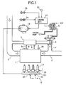
- Fig. 1 shows an engine structure for performing a low-temperature-premixed combustion. This general structure is disclosed in Japanese Unexamined Patent Publication No. 8 - 86251, though the unique control method described below is not in the JP publication.
- an EGR passage connecting an exhaust passage of an engine 1 to an intake passage thereof is equipped with a diaphragm type EGR valve 6 driven by a control negative pressure from a negative pressure control valve 5.
- Negative pressure control valve 5 is driven by a duty control signal from a control unit 41 to obtain a certain EGR rate corresponding to an engine operating condition.
- a cooling apparatus 7 for EGR gases is disposed about a half way in EGR passage 4. Cooling apparatus 7 is formed around EGR passage 4 and comprises a water jacket 8 where part of an engine cooling water is recirculated, and a flow control valve 9 disposed at an introduction port 8a of the cooling water will adjust a recirculation quantity of the cooling water.
- Fuel injection apparatus 10 comprises a fuel tank 11, a fuel supply passage 12, a supply pump 14, a fuel supply passage 15, a common rail 16, and a fuel injection nozzle 17 disposed for each cylinder.
- the fuel pressurized by supply pump 14 is stored in common rail 16 through fuel supply passage 15 for some predetermined time and then is distributed to fuel injection nozzle 17 for each cylinder.
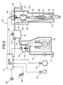
- Fuel injection nozzle 17 comprises a needle valve 18, a nozzle chamber 19, a fuel supply passage 20 from common rail 16 to nozzle chamber 19, a retainer 21 attached to needle valve 18, an oil pressure piston 22 which can push needle valve 18 in a closing direction thereof through retainer 21, a return spring 23 which forces needle valve 18 in a closing direction thereof through retainer 21, a fuel supply passage 24 to oil pressure piston 22, a three-way electromagnetic valve 25 inserted in fuel supply passage 24, and a one-way delay valve (one-way valve 26 positioned paralleled to an orifice 27) inserted in fuel supply passage 24.
- Opening and closing needle valve 18 are controlled by three-way valve 25.
- Control unit 41 receives signals for various controls from a pressure sensor 32 which detects a pressure (injection pressure) in common rail 16, an acceleration opening degree sensor 33 which detects an acceleration opening degree, an engine rotation speed sensor 34 which detects an engine rotation speed, a cylinder-identification sensor 35 which identifies a cylinder, a water temperature sensor 36 which detects an engine water temperature, and a fuel temperature sensor 37 which detects a fuel temperature.
- step S 1 an engine rotation speed Ne, an acceleration opening degree ACC, an engine water temperature TW, and a fuel temperature TF are read.
- a basic injection timing ITm and a basic injection period ITdm are set based upon parameters of an engine operating condition which are engine rotation speed Ne and acceleration opening degree ACC.
- an injection timing correction quantity ⁇ IT and an injection period correction quantity ⁇ ITd are set based upon engine water temperature TW and / or fuel temperature TF.
- step S 5 the injection timing IT and the injection period ITd determined at step S 4 are stored at a predetermined address and a fuel injection control is performed based upon these IT and ITd.
- the control unit judges whether or not its correction is necessary.
- ITd basic injection period
- the injection period is prolonged by lowering an injection pressure (fuel pressure in the common rail) and thereby, a difference between an injection completion timing and an ignition start timing (i.e., start of premixed combustion) is controlled to be within 15 degrees of a crank angle.
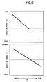
- Controlling injection timing and injection period corresponding to a change of water temperature TW and fuel temperature TF is shown in Fig. 4 and 5. With lower temperature, the injection timing IT is increasingly advanced more and the injection period ITd is increasingly prolonged.
- Fig. 6 An effect of this embodiment is shown in Fig. 6 where an emission quantity of smokes and an emission quantity of unburned HC are shown related to the difference between the injection period and the ignition delay period (injection period - ignition delay period.
- the difference is increased on the negative side as an injection completion timing is earlier than an ignition start timing.
- the smokes can be reduced by a large margin due to the ignition delay period being longer than the injection period by nature of a low- temperature premixed combustion.
- injection period - ignition delay period 0
- injection period - ignition delay period 5 CA
- injection period - ignition delay period 5 CA
- the time for the fuel to disperse becomes short and an equivalent ratio distribution in a cylinder becomes extremely rich.
- the equivalent ratio distribution becomes very lean.
- an emission quantity of unburned HC increases rapidly caused by a decrease of a combustion temperature in addition to this above condition.
- an equivalent ratio in the vicinity of a cylinder center becomes richer compared with the ratio in the vicinity of a cylinder wall and also a change of the equivalent ratio from the vicinity of the cylinder center to the vicinity of the cylinder wall becomes slow, which provides an optimal characteristic.
- the maximum equivalent ratio may be somewhat off the cylinder center; it need not be right at the cylinder center itself.
- an emission quantity of smokes and HC has a relation with a period of from the fuel injection completion to the ignition delay period (injection period - ignition delay period), as shown in Fig. 6 and when the condition is met where - 15 degrees ⁇ injection period - ignition delay period ⁇ 0 degree, both smokes and unburned HC can be reduced.
- An equivalent ratio distribution varies corresponding to a change of period from the fuel injection completion to the ignition start as shown in Fig. 7.
- the equivalent ratio distribution is controlled as a thick line in Fig. 7(such as the difference between injection period and ignition delay period equal to 0 CA or -10 CA), both smokes and HC can be reduced.
- an equivalent ratio distribution in the combustion chamber at an ignition start is controlled such that an equivalent ratio in the vicinity of the cylinder center is relatively richer compared with that in the vicinity of the cylinder wall and also a change of an equivalent ratio from the cylinder center vicinity to the cylinder wall vicinity is relatively smooth.
- a crank angle from the injection completion to the ignition start at controlling the equivalent ratio smaller than a predetermined crank angle (namely, a crank angle where an emission quantity of unburned HC starts to increase rapidly)
- a predetermined crank angle namely, a crank angle where an emission quantity of unburned HC starts to increase rapidly
- an optimal equivalent ratio distribution can be made and both smokes and unburned HC can be reduced.
- the equivalent ratio based upon a crank angle the potential negative influence of disturbance due to an engine rotation number is eliminated and regardless of the engine rotation number, a proper effect can always be achieved.
- the relationship - 15 degrees ⁇ injection period - ignition delay period ⁇ 0 degree can be achieved.
- Either the injection timing or the injection period may be controlled as follows (1) or (2).
- a crank angle from the injection completion to the ignition start does not becomes less than 15 degrees all the time only by advancing the injection timing, but when together with prolonging the injection period, it becomes less than 15 degrees.
- the combustion start timing does not change all the time as desired only by prolonging the injection period. That is, the combustion start is kept delayed as shown in Fig. 8 (d), but when together with advancing the fuel injection timing, the combustion start timing can be set as the optimal timing (about 15 degrees after a top dead center is desirable) as in Fig. 8 (e).
- a fuel injection period is prolonged by decreasing a fuel injection pressure and as a result, the period from the fuel injection completion to the ignition start is shortened. Accordingly, an overspreading of the fuel into the combustion chamber is prevented and the optimal equivalent ratio distribution is obtained by a relatively simple control of the fuel injection pressure.
- the fuel injection period is prolonged by lowering the fuel injection pressure, but other than that, an injection rate is lowered by controlling a lift quantity of a needle valve (it is limited to a case of a fuel injection nozzle capable of randomly controlling the needle valve lift quantity by an piezoelectric element) so that the injection period can be prolonged.
- Fig. 9 shows an injection rate pattern compared with an earlier example.
- a split injection is used.
- Control of the split injection such as in the common rail system in Fig. 2, can be performed by switching a three-way electromagnetic valve (off-on-off-on-off).
- time from an injection completion to an ignition start is not controlled, but an equivalent ratio distribution is still controlled.
- the equivalent ratio distribution is positively controlled toward a rich side. In this case, a rich portion at a combustion center is more effectively formed that is less influenced by squish and swirl.
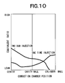
- Fig. 10 shows an effect to an equivalent ratio distribution in case of the split injection (two sub-injections) compared with a one-time injection.
- a penetration of a first fuel spray is weakened, a fuel injection velocity is slowed down, and the fuel remains in the vicinity of the fuel injection nozzle. Accordingly, a rich mixture is formed at a combustion chamber center and this rich mixture spreads out by the time of the ignition and at the ignition time such that an equivalent ratio distribution proper for a low-temperature premixed combustion can be made.
- the equivalent ratio distribution is controlled by decreasing a fuel injection rate to decrease the spreading of the fuel into the combustion chamber and an emission quantity increase of unburned HC is restricted.
- the fuel injection rate is reduced at low load or low temperature when the ignition delay period becomes long and HC increase, so that even when the fuel injection period is relatively short, the spread of the fuel is prevented and HC increase due to too much leanness can be prevented.
- the split injection of the fuel is used for reducing the fuel injection rate and as a result, the spread of the fuel is prevented by a weakened penetration of the fuel spray and the fuel spray can be floated at the combustion chamber center.
Landscapes
- Engineering & Computer Science (AREA)
- Chemical & Material Sciences (AREA)
- Combustion & Propulsion (AREA)
- Mechanical Engineering (AREA)
- General Engineering & Computer Science (AREA)
- Physics & Mathematics (AREA)
- Fluid Mechanics (AREA)
- Electrical Control Of Air Or Fuel Supplied To Internal-Combustion Engine (AREA)
- Combustion Methods Of Internal-Combustion Engines (AREA)
- Exhaust-Gas Circulating Devices (AREA)
- Output Control And Ontrol Of Special Type Engine (AREA)
- Combined Controls Of Internal Combustion Engines (AREA)
Applications Claiming Priority (2)
| Application Number | Priority Date | Filing Date | Title |
|---|---|---|---|
| JP2001385071 | 2001-12-18 | ||
| JP2001385071A JP3893967B2 (ja) | 2001-12-18 | 2001-12-18 | ディーゼルエンジンの制御装置 |
Publications (3)
| Publication Number | Publication Date |
|---|---|
| EP1321650A2 true EP1321650A2 (fr) | 2003-06-25 |
| EP1321650A3 EP1321650A3 (fr) | 2005-06-08 |
| EP1321650B1 EP1321650B1 (fr) | 2008-05-28 |
Family
ID=19187788
Family Applications (1)
| Application Number | Title | Priority Date | Filing Date |
|---|---|---|---|
| EP02026412A Expired - Lifetime EP1321650B1 (fr) | 2001-12-18 | 2002-11-26 | Appareil et méthode de commande d'un moteur diesel |
Country Status (4)
| Country | Link |
|---|---|
| US (1) | US6742492B2 (fr) |
| EP (1) | EP1321650B1 (fr) |
| JP (1) | JP3893967B2 (fr) |
| DE (1) | DE60226828D1 (fr) |
Cited By (2)
| Publication number | Priority date | Publication date | Assignee | Title |
|---|---|---|---|---|
| EP1785616A3 (fr) * | 2005-10-24 | 2009-01-07 | Ford Global Technologies, LLC | Procédé d'exploitation d'un moteur thermique |
| US7848871B2 (en) | 2005-03-30 | 2010-12-07 | Toyota Jidosha Kabushiki Kaisha | Gas-mixture-state estimation apparatus for internal combustion engine and emission-generation-amount estimation apparatus |
Families Citing this family (17)
| Publication number | Priority date | Publication date | Assignee | Title |
|---|---|---|---|---|
| JP4161635B2 (ja) * | 2002-08-19 | 2008-10-08 | 株式会社デンソー | 燃料噴射制御装置 |
| EP1491740B1 (fr) * | 2003-06-24 | 2008-02-27 | Ford Global Technologies, LLC, A subsidary of Ford Motor Company | Procédé de fonctionnement d'un moteur Diesel |
| JP4251123B2 (ja) * | 2003-11-04 | 2009-04-08 | 株式会社デンソー | 内燃機関 |
| CN100354507C (zh) * | 2005-03-11 | 2007-12-12 | 大连理工大学 | 柴油机预混合燃烧系统 |
| US7533518B2 (en) * | 2005-05-12 | 2009-05-19 | Ford Global Technologies, Llc | System and method for reducing NOx emissions in an apparatus having a diesel engine |
| DE102005057571A1 (de) * | 2005-12-02 | 2007-06-06 | Robert Bosch Gmbh | Verfahren zur Ansteuerung eines Kraftstoff-Injektors eines Dieselmotors |
| JP4716283B2 (ja) * | 2006-02-08 | 2011-07-06 | 本田技研工業株式会社 | 内燃機関の空燃比制御装置 |
| JP2007332815A (ja) * | 2006-06-13 | 2007-12-27 | Mazda Motor Corp | ディーゼルエンジンの制御装置 |
| DE102008000916B4 (de) * | 2007-04-02 | 2021-12-16 | Denso Corporation | Verbrennungssteuerungsvorrichtung für direkt einspritzende Kompressionszündungskraftmaschine |
| US20110030635A1 (en) * | 2009-08-04 | 2011-02-10 | International Engine Intellectual Property Company, Llc | Fuel injector nozzle for reduced coking |
| JP2011163251A (ja) * | 2010-02-12 | 2011-08-25 | Mitsubishi Heavy Ind Ltd | ディーゼルエンジンの燃料噴射制御装置および方法 |
| US8051829B2 (en) | 2010-10-08 | 2011-11-08 | Ford Global Technologies, Llc | Method for controlling low temperature combustion |
| US8899209B2 (en) | 2010-10-08 | 2014-12-02 | Ford Global Technologies, Llc | System and method for compensating cetane |
| US8949002B2 (en) | 2012-02-21 | 2015-02-03 | Ford Global Technologies, Llc | System and method for injecting fuel |
| CN103437929B (zh) * | 2013-07-16 | 2016-01-27 | 江苏大学 | 一种可精确控制柴油机喷油温度的燃油系统及控制方法 |
| US10731544B2 (en) * | 2018-09-24 | 2020-08-04 | Caterpillar Inc. | Internal combustion engine and method for its operation |
| CN113586274B (zh) * | 2021-09-14 | 2023-01-24 | 潍柴动力股份有限公司 | 一种发动机喷射角度控制方法及发动机 |
Citations (2)
| Publication number | Priority date | Publication date | Assignee | Title |
|---|---|---|---|---|
| JPH0886251A (ja) | 1994-09-19 | 1996-04-02 | Nissan Motor Co Ltd | ディーゼルエンジン |
| JP2864896B2 (ja) | 1992-10-01 | 1999-03-08 | 日産自動車株式会社 | ディーゼルエンジンの制御装置 |
Family Cites Families (6)
| Publication number | Priority date | Publication date | Assignee | Title |
|---|---|---|---|---|
| DE69830818T2 (de) * | 1997-05-21 | 2005-12-29 | Nissan Motor Co., Ltd., Yokohama | Übergangsregelsystem zwischen zwei funkengezündeten Brennzuständen in einem Motor |
| JPH11153056A (ja) * | 1997-11-21 | 1999-06-08 | Nissan Motor Co Ltd | ディーゼルエンジンの制御装置 |
| JP3598775B2 (ja) * | 1997-11-25 | 2004-12-08 | 日産自動車株式会社 | ディーゼルエンジンの制御装置 |
| JP3915329B2 (ja) * | 1999-07-21 | 2007-05-16 | 日産自動車株式会社 | ディーゼルエンジンの燃料噴射制御装置 |
| DE19953932C2 (de) * | 1999-11-10 | 2002-04-18 | Daimler Chrysler Ag | Verfahren zum Betrieb einer Hubkolbenbrennkraftmaschine |
| US6390057B2 (en) * | 1999-12-14 | 2002-05-21 | Nissan Motor Co., Ltd. | Compression self-ignition gasoline engine |
-
2001
- 2001-12-18 JP JP2001385071A patent/JP3893967B2/ja not_active Expired - Fee Related
-
2002
- 2002-11-21 US US10/300,741 patent/US6742492B2/en not_active Expired - Fee Related
- 2002-11-26 EP EP02026412A patent/EP1321650B1/fr not_active Expired - Lifetime
- 2002-11-26 DE DE60226828T patent/DE60226828D1/de not_active Expired - Lifetime
Patent Citations (2)
| Publication number | Priority date | Publication date | Assignee | Title |
|---|---|---|---|---|
| JP2864896B2 (ja) | 1992-10-01 | 1999-03-08 | 日産自動車株式会社 | ディーゼルエンジンの制御装置 |
| JPH0886251A (ja) | 1994-09-19 | 1996-04-02 | Nissan Motor Co Ltd | ディーゼルエンジン |
Cited By (2)
| Publication number | Priority date | Publication date | Assignee | Title |
|---|---|---|---|---|
| US7848871B2 (en) | 2005-03-30 | 2010-12-07 | Toyota Jidosha Kabushiki Kaisha | Gas-mixture-state estimation apparatus for internal combustion engine and emission-generation-amount estimation apparatus |
| EP1785616A3 (fr) * | 2005-10-24 | 2009-01-07 | Ford Global Technologies, LLC | Procédé d'exploitation d'un moteur thermique |
Also Published As
| Publication number | Publication date |
|---|---|
| US20030111041A1 (en) | 2003-06-19 |
| EP1321650B1 (fr) | 2008-05-28 |
| EP1321650A3 (fr) | 2005-06-08 |
| US6742492B2 (en) | 2004-06-01 |
| JP2003184609A (ja) | 2003-07-03 |
| DE60226828D1 (de) | 2008-07-10 |
| JP3893967B2 (ja) | 2007-03-14 |
Similar Documents
| Publication | Publication Date | Title |
|---|---|---|
| US6742492B2 (en) | Apparatus and a method for controlling a diesel engine | |
| EP0767303B1 (fr) | Moteur diesel | |
| US9255539B2 (en) | Spark-ignition direct injection engine | |
| US6745743B2 (en) | Control apparatus for a direct injection engine | |
| US7137379B2 (en) | Method for rich pulse control of diesel engines | |
| US20040154582A1 (en) | Combustion control device and method for engine | |
| EP1803918B1 (fr) | Contrôleur de moteur diesel | |
| BRPI0713716A2 (pt) | motor de combustão interna de combustìvel múltiplo | |
| JP2000120457A (ja) | ディーゼルエンジン | |
| US10968859B2 (en) | Premixed compression ignition engine and method for controlling premixed compression ignition engine | |
| US10344693B2 (en) | Control apparatus for gasoline engine | |
| JPH10141124A (ja) | ディーゼルエンジン | |
| JP2010007584A (ja) | 燃料噴射制御装置 | |
| JP4232590B2 (ja) | 圧縮着火式内燃機関の燃焼制御システム | |
| JP3514086B2 (ja) | ディーゼルエンジンの燃焼制御装置 | |
| JPH0583730B2 (fr) | ||
| JP4586670B2 (ja) | 予混合圧縮着火内燃機関 | |
| EP1156202B1 (fr) | Moteur à combustion interne | |
| JP4124134B2 (ja) | 内燃機関の燃料噴射制御方法 | |
| JP4026197B2 (ja) | 筒内直接噴射式内燃機関の燃料噴射制御装置 | |
| JPH0583729B2 (fr) | ||
| JPH09264163A (ja) | 多気筒ディーゼルエンジンの燃料供給装置 | |
| JP2002322922A (ja) | ディーゼルエンジン | |
| JPH10252607A (ja) | ディーゼル機関の排ガス浄化装置 | |
| JP2007211596A (ja) | ディーゼルエンジンの燃焼切換制御方法及び装置 |
Legal Events
| Date | Code | Title | Description |
|---|---|---|---|
| PUAI | Public reference made under article 153(3) epc to a published international application that has entered the european phase |
Free format text: ORIGINAL CODE: 0009012 |
|
| 17P | Request for examination filed |
Effective date: 20021126 |
|
| AK | Designated contracting states |
Designated state(s): AT BE BG CH CY CZ DE DK EE ES FI FR GB GR IE IT LI LU MC NL PT SE SK TR |
|
| AX | Request for extension of the european patent |
Extension state: AL LT LV MK RO SI |
|
| PUAL | Search report despatched |
Free format text: ORIGINAL CODE: 0009013 |
|
| AK | Designated contracting states |
Kind code of ref document: A3 Designated state(s): AT BE BG CH CY CZ DE DK EE ES FI FR GB GR IE IT LI LU MC NL PT SE SK TR |
|
| AX | Request for extension of the european patent |
Extension state: AL LT LV MK RO SI |
|
| AKX | Designation fees paid |
Designated state(s): DE FR GB |
|
| GRAP | Despatch of communication of intention to grant a patent |
Free format text: ORIGINAL CODE: EPIDOSNIGR1 |
|
| GRAS | Grant fee paid |
Free format text: ORIGINAL CODE: EPIDOSNIGR3 |
|
| GRAA | (expected) grant |
Free format text: ORIGINAL CODE: 0009210 |
|
| AK | Designated contracting states |
Kind code of ref document: B1 Designated state(s): DE FR GB |
|
| REG | Reference to a national code |
Ref country code: GB Ref legal event code: FG4D |
|
| REF | Corresponds to: |
Ref document number: 60226828 Country of ref document: DE Date of ref document: 20080710 Kind code of ref document: P |
|
| PLBE | No opposition filed within time limit |
Free format text: ORIGINAL CODE: 0009261 |
|
| STAA | Information on the status of an ep patent application or granted ep patent |
Free format text: STATUS: NO OPPOSITION FILED WITHIN TIME LIMIT |
|
| 26N | No opposition filed |
Effective date: 20090303 |
|
| PGFP | Annual fee paid to national office [announced via postgrant information from national office to epo] |
Ref country code: FR Payment date: 20131108 Year of fee payment: 12 Ref country code: DE Payment date: 20131120 Year of fee payment: 12 Ref country code: GB Payment date: 20131120 Year of fee payment: 12 |
|
| REG | Reference to a national code |
Ref country code: DE Ref legal event code: R119 Ref document number: 60226828 Country of ref document: DE |
|
| GBPC | Gb: european patent ceased through non-payment of renewal fee |
Effective date: 20141126 |
|
| REG | Reference to a national code |
Ref country code: FR Ref legal event code: ST Effective date: 20150731 |
|
| PG25 | Lapsed in a contracting state [announced via postgrant information from national office to epo] |
Ref country code: GB Free format text: LAPSE BECAUSE OF NON-PAYMENT OF DUE FEES Effective date: 20141126 Ref country code: DE Free format text: LAPSE BECAUSE OF NON-PAYMENT OF DUE FEES Effective date: 20150602 |
|
| PG25 | Lapsed in a contracting state [announced via postgrant information from national office to epo] |
Ref country code: FR Free format text: LAPSE BECAUSE OF NON-PAYMENT OF DUE FEES Effective date: 20141201 |