EP1491740B1 - Procédé de fonctionnement d'un moteur Diesel - Google Patents
Procédé de fonctionnement d'un moteur Diesel Download PDFInfo
- Publication number
- EP1491740B1 EP1491740B1 EP03101845A EP03101845A EP1491740B1 EP 1491740 B1 EP1491740 B1 EP 1491740B1 EP 03101845 A EP03101845 A EP 03101845A EP 03101845 A EP03101845 A EP 03101845A EP 1491740 B1 EP1491740 B1 EP 1491740B1
- Authority
- EP
- European Patent Office
- Prior art keywords
- fuel
- approx
- dead center
- top dead
- piston
- Prior art date
- Legal status (The legal status is an assumption and is not a legal conclusion. Google has not performed a legal analysis and makes no representation as to the accuracy of the status listed.)
- Expired - Lifetime
Links
- 238000000034 method Methods 0.000 title claims description 28
- 239000000446 fuel Substances 0.000 claims description 90
- 238000002347 injection Methods 0.000 claims description 68
- 239000007924 injection Substances 0.000 claims description 68
- 238000002485 combustion reaction Methods 0.000 claims description 60
- 239000007789 gas Substances 0.000 claims description 19
- 230000006835 compression Effects 0.000 claims description 16
- 238000007906 compression Methods 0.000 claims description 16
- 230000015572 biosynthetic process Effects 0.000 claims description 10
- 239000000203 mixture Substances 0.000 claims description 10
- 239000007921 spray Substances 0.000 claims description 3
- 238000001816 cooling Methods 0.000 claims description 2
- 238000010791 quenching Methods 0.000 claims 1
- 239000004071 soot Substances 0.000 description 10
- 206010053615 Thermal burn Diseases 0.000 description 4
- 238000009792 diffusion process Methods 0.000 description 3
- 239000008240 homogeneous mixture Substances 0.000 description 3
- 230000008901 benefit Effects 0.000 description 2
- 238000006243 chemical reaction Methods 0.000 description 2
- 238000010586 diagram Methods 0.000 description 2
- 230000000694 effects Effects 0.000 description 2
- 239000003344 environmental pollutant Substances 0.000 description 2
- 231100000719 pollutant Toxicity 0.000 description 2
- 230000007704 transition Effects 0.000 description 2
- 240000003517 Elaeocarpus dentatus Species 0.000 description 1
- 230000001419 dependent effect Effects 0.000 description 1
- 238000013461 design Methods 0.000 description 1
- 238000011161 development Methods 0.000 description 1
- 238000006073 displacement reaction Methods 0.000 description 1
- 238000002474 experimental method Methods 0.000 description 1
- 239000008241 heterogeneous mixture Substances 0.000 description 1
- 238000005457 optimization Methods 0.000 description 1
- 238000012552 review Methods 0.000 description 1
- 238000007493 shaping process Methods 0.000 description 1
- 239000007787 solid Substances 0.000 description 1
- XLYOFNOQVPJJNP-UHFFFAOYSA-N water Substances O XLYOFNOQVPJJNP-UHFFFAOYSA-N 0.000 description 1
Images



Classifications
-
- F—MECHANICAL ENGINEERING; LIGHTING; HEATING; WEAPONS; BLASTING
- F02—COMBUSTION ENGINES; HOT-GAS OR COMBUSTION-PRODUCT ENGINE PLANTS
- F02B—INTERNAL-COMBUSTION PISTON ENGINES; COMBUSTION ENGINES IN GENERAL
- F02B1/00—Engines characterised by fuel-air mixture compression
- F02B1/12—Engines characterised by fuel-air mixture compression with compression ignition
-
- F—MECHANICAL ENGINEERING; LIGHTING; HEATING; WEAPONS; BLASTING
- F02—COMBUSTION ENGINES; HOT-GAS OR COMBUSTION-PRODUCT ENGINE PLANTS
- F02B—INTERNAL-COMBUSTION PISTON ENGINES; COMBUSTION ENGINES IN GENERAL
- F02B1/00—Engines characterised by fuel-air mixture compression
- F02B1/12—Engines characterised by fuel-air mixture compression with compression ignition
- F02B1/14—Methods of operating
-
- F—MECHANICAL ENGINEERING; LIGHTING; HEATING; WEAPONS; BLASTING
- F02—COMBUSTION ENGINES; HOT-GAS OR COMBUSTION-PRODUCT ENGINE PLANTS
- F02B—INTERNAL-COMBUSTION PISTON ENGINES; COMBUSTION ENGINES IN GENERAL
- F02B23/00—Other engines characterised by special shape or construction of combustion chambers to improve operation
- F02B23/02—Other engines characterised by special shape or construction of combustion chambers to improve operation with compression ignition
- F02B23/06—Other engines characterised by special shape or construction of combustion chambers to improve operation with compression ignition the combustion space being arranged in working piston
-
- F—MECHANICAL ENGINEERING; LIGHTING; HEATING; WEAPONS; BLASTING
- F02—COMBUSTION ENGINES; HOT-GAS OR COMBUSTION-PRODUCT ENGINE PLANTS
- F02D—CONTROLLING COMBUSTION ENGINES
- F02D15/00—Varying compression ratio
-
- F—MECHANICAL ENGINEERING; LIGHTING; HEATING; WEAPONS; BLASTING
- F02—COMBUSTION ENGINES; HOT-GAS OR COMBUSTION-PRODUCT ENGINE PLANTS
- F02D—CONTROLLING COMBUSTION ENGINES
- F02D41/00—Electrical control of supply of combustible mixture or its constituents
- F02D41/0025—Controlling engines characterised by use of non-liquid fuels, pluralities of fuels, or non-fuel substances added to the combustible mixtures
- F02D41/0047—Controlling exhaust gas recirculation [EGR]
- F02D41/005—Controlling exhaust gas recirculation [EGR] according to engine operating conditions
- F02D41/0057—Specific combustion modes
-
- F—MECHANICAL ENGINEERING; LIGHTING; HEATING; WEAPONS; BLASTING
- F02—COMBUSTION ENGINES; HOT-GAS OR COMBUSTION-PRODUCT ENGINE PLANTS
- F02D—CONTROLLING COMBUSTION ENGINES
- F02D41/00—Electrical control of supply of combustible mixture or its constituents
- F02D41/30—Controlling fuel injection
- F02D41/3011—Controlling fuel injection according to or using specific or several modes of combustion
- F02D41/3017—Controlling fuel injection according to or using specific or several modes of combustion characterised by the mode(s) being used
- F02D41/3035—Controlling fuel injection according to or using specific or several modes of combustion characterised by the mode(s) being used a mode being the premixed charge compression-ignition mode
-
- F—MECHANICAL ENGINEERING; LIGHTING; HEATING; WEAPONS; BLASTING
- F02—COMBUSTION ENGINES; HOT-GAS OR COMBUSTION-PRODUCT ENGINE PLANTS
- F02D—CONTROLLING COMBUSTION ENGINES
- F02D41/00—Electrical control of supply of combustible mixture or its constituents
- F02D41/30—Controlling fuel injection
- F02D41/3011—Controlling fuel injection according to or using specific or several modes of combustion
- F02D41/3017—Controlling fuel injection according to or using specific or several modes of combustion characterised by the mode(s) being used
- F02D41/3035—Controlling fuel injection according to or using specific or several modes of combustion characterised by the mode(s) being used a mode being the premixed charge compression-ignition mode
- F02D41/3041—Controlling fuel injection according to or using specific or several modes of combustion characterised by the mode(s) being used a mode being the premixed charge compression-ignition mode with means for triggering compression ignition, e.g. spark plug
- F02D41/3047—Controlling fuel injection according to or using specific or several modes of combustion characterised by the mode(s) being used a mode being the premixed charge compression-ignition mode with means for triggering compression ignition, e.g. spark plug said means being a secondary injection of fuel
-
- F—MECHANICAL ENGINEERING; LIGHTING; HEATING; WEAPONS; BLASTING
- F02—COMBUSTION ENGINES; HOT-GAS OR COMBUSTION-PRODUCT ENGINE PLANTS
- F02D—CONTROLLING COMBUSTION ENGINES
- F02D41/00—Electrical control of supply of combustible mixture or its constituents
- F02D41/30—Controlling fuel injection
- F02D41/38—Controlling fuel injection of the high pressure type
- F02D41/40—Controlling fuel injection of the high pressure type with means for controlling injection timing or duration
- F02D41/402—Multiple injections
-
- F—MECHANICAL ENGINEERING; LIGHTING; HEATING; WEAPONS; BLASTING
- F02—COMBUSTION ENGINES; HOT-GAS OR COMBUSTION-PRODUCT ENGINE PLANTS
- F02B—INTERNAL-COMBUSTION PISTON ENGINES; COMBUSTION ENGINES IN GENERAL
- F02B2275/00—Other engines, components or details, not provided for in other groups of this subclass
- F02B2275/14—Direct injection into combustion chamber
-
- F—MECHANICAL ENGINEERING; LIGHTING; HEATING; WEAPONS; BLASTING
- F02—COMBUSTION ENGINES; HOT-GAS OR COMBUSTION-PRODUCT ENGINE PLANTS
- F02B—INTERNAL-COMBUSTION PISTON ENGINES; COMBUSTION ENGINES IN GENERAL
- F02B23/00—Other engines characterised by special shape or construction of combustion chambers to improve operation
- F02B23/02—Other engines characterised by special shape or construction of combustion chambers to improve operation with compression ignition
- F02B23/06—Other engines characterised by special shape or construction of combustion chambers to improve operation with compression ignition the combustion space being arranged in working piston
- F02B23/0618—Other engines characterised by special shape or construction of combustion chambers to improve operation with compression ignition the combustion space being arranged in working piston having in-cylinder means to influence the charge motion
- F02B23/0621—Squish flow
-
- F—MECHANICAL ENGINEERING; LIGHTING; HEATING; WEAPONS; BLASTING
- F02—COMBUSTION ENGINES; HOT-GAS OR COMBUSTION-PRODUCT ENGINE PLANTS
- F02B—INTERNAL-COMBUSTION PISTON ENGINES; COMBUSTION ENGINES IN GENERAL
- F02B23/00—Other engines characterised by special shape or construction of combustion chambers to improve operation
- F02B23/02—Other engines characterised by special shape or construction of combustion chambers to improve operation with compression ignition
- F02B23/06—Other engines characterised by special shape or construction of combustion chambers to improve operation with compression ignition the combustion space being arranged in working piston
- F02B23/0618—Other engines characterised by special shape or construction of combustion chambers to improve operation with compression ignition the combustion space being arranged in working piston having in-cylinder means to influence the charge motion
- F02B23/0624—Swirl flow
-
- F—MECHANICAL ENGINEERING; LIGHTING; HEATING; WEAPONS; BLASTING
- F02—COMBUSTION ENGINES; HOT-GAS OR COMBUSTION-PRODUCT ENGINE PLANTS
- F02B—INTERNAL-COMBUSTION PISTON ENGINES; COMBUSTION ENGINES IN GENERAL
- F02B23/00—Other engines characterised by special shape or construction of combustion chambers to improve operation
- F02B23/02—Other engines characterised by special shape or construction of combustion chambers to improve operation with compression ignition
- F02B23/06—Other engines characterised by special shape or construction of combustion chambers to improve operation with compression ignition the combustion space being arranged in working piston
- F02B23/0636—Other engines characterised by special shape or construction of combustion chambers to improve operation with compression ignition the combustion space being arranged in working piston the combustion space having a substantially flat and horizontal bottom
- F02B23/0639—Other engines characterised by special shape or construction of combustion chambers to improve operation with compression ignition the combustion space being arranged in working piston the combustion space having a substantially flat and horizontal bottom the combustion space having substantially the shape of a cylinder
-
- F—MECHANICAL ENGINEERING; LIGHTING; HEATING; WEAPONS; BLASTING
- F02—COMBUSTION ENGINES; HOT-GAS OR COMBUSTION-PRODUCT ENGINE PLANTS
- F02B—INTERNAL-COMBUSTION PISTON ENGINES; COMBUSTION ENGINES IN GENERAL
- F02B3/00—Engines characterised by air compression and subsequent fuel addition
- F02B3/06—Engines characterised by air compression and subsequent fuel addition with compression ignition
-
- F—MECHANICAL ENGINEERING; LIGHTING; HEATING; WEAPONS; BLASTING
- F02—COMBUSTION ENGINES; HOT-GAS OR COMBUSTION-PRODUCT ENGINE PLANTS
- F02D—CONTROLLING COMBUSTION ENGINES
- F02D2250/00—Engine control related to specific problems or objectives
- F02D2250/36—Control for minimising NOx emissions
-
- Y—GENERAL TAGGING OF NEW TECHNOLOGICAL DEVELOPMENTS; GENERAL TAGGING OF CROSS-SECTIONAL TECHNOLOGIES SPANNING OVER SEVERAL SECTIONS OF THE IPC; TECHNICAL SUBJECTS COVERED BY FORMER USPC CROSS-REFERENCE ART COLLECTIONS [XRACs] AND DIGESTS
- Y02—TECHNOLOGIES OR APPLICATIONS FOR MITIGATION OR ADAPTATION AGAINST CLIMATE CHANGE
- Y02T—CLIMATE CHANGE MITIGATION TECHNOLOGIES RELATED TO TRANSPORTATION
- Y02T10/00—Road transport of goods or passengers
- Y02T10/10—Internal combustion engine [ICE] based vehicles
- Y02T10/12—Improving ICE efficiencies
-
- Y—GENERAL TAGGING OF NEW TECHNOLOGICAL DEVELOPMENTS; GENERAL TAGGING OF CROSS-SECTIONAL TECHNOLOGIES SPANNING OVER SEVERAL SECTIONS OF THE IPC; TECHNICAL SUBJECTS COVERED BY FORMER USPC CROSS-REFERENCE ART COLLECTIONS [XRACs] AND DIGESTS
- Y02—TECHNOLOGIES OR APPLICATIONS FOR MITIGATION OR ADAPTATION AGAINST CLIMATE CHANGE
- Y02T—CLIMATE CHANGE MITIGATION TECHNOLOGIES RELATED TO TRANSPORTATION
- Y02T10/00—Road transport of goods or passengers
- Y02T10/10—Internal combustion engine [ICE] based vehicles
- Y02T10/40—Engine management systems
Definitions
- the invention relates to a method for operating a diesel engine with direct injection in different operating modes and to a diesel engine arranged for carrying out the method.
- the engine control and engine are designed so that mixture formation and combustion occurs in a relatively narrow angular range about top dead center of the piston.
- the usual combustion mode in such a diesel engine is therefore characterized by a short phase of the ignition delay, followed by a combustion phase with premixing and diffusion. Due to the preferred ignition of the heterogeneous mixture in fuel-rich zones, there is an increased formation of soot. As soot formation increases with increasing exhaust gas recirculation rate, the latter can not be increased as much as would be desirable to reduce NOx emissions.
- a method of operating a direct injection diesel engine in which different modes of operation are performed in different load ranges of the engine.
- a homogeneous fuel combustion can take place in a range of small to medium loads, wherein the fuel is to be injected between 180 ° and 20 ° before top dead center of the piston.
- the homogeneous combustion should optionally be supplemented by an additional heterogeneous combustion with a fuel injection in the vicinity of the top dead center (see Figure 9).
- pollutant emissions is in the DE 199 53 932 A1 not received.
- the proposed method can achieve a significant reduction of NOx and soot emissions in the range of small and medium engine loads. This makes it possible, at the same time to meet the increasingly stringent emission requirements for motor vehicles with good fuel efficiency.
- the fuel injection during the two operating modes A and B of the method is preferably carried out at a fuel pressure between 300 and 2000 bar.
- the ignition delay of the homogeneous combustion so large that the formation of the homogeneous mixture takes place at least partially in the vicinity of the top dead center of the piston, and that the maximum heat release from this combustion takes place after top dead center of the piston.
- Such a setting of the ignition delay can be generated in particular by a reduced compression ratio (typically between 12 and 16), by cooling the recirculated exhaust gases, by a wall-guided flow of the mixture in the cylinder and / or by the shaping of a piston recess on the upper side of the piston.
- the high ignition delay makes it possible to significantly expand the work area with low NOx and soot emissions. Furthermore, the high ignition delay contributes to a reduction in noise as well as a reduction in the maximum cylinder pressure.
- the method optionally further comprises at least one further mode of operation, which is preferably carried out at high load and / or at full load of the engine.
- this mode of operation can also be extended to areas of medium and smaller loads as needed.
- a heterogeneous combustion of the fuel takes place, wherein at least one fuel injection takes place in the vicinity of the top dead center, ie in particular in a range of ⁇ 20 ° around the top dead center.
- This operating mode thus essentially corresponds to the conventional operation of a diesel engine with direct injection.
- the quantity of fuel intended for homogeneous combustion in operating mode A and / or B is injected into two phases, namely an early fuel injection and a late fuel injection.
- the early fuel injection preferably takes place between approximately 120 ° to 60 ° before top dead center and the late fuel injection preferably between approximately 25 ° and 0 ° before top dead center.
- the time of the early injection is a well-suited parameter with which the beginning of the combustion and thus the main heat release can be controlled.
- the distribution of the fuel quantity to the first and the second injection depends on the respective boundary conditions.
- the early fuel injection is preferably directed into the nip chamber adjacent to the piston bowl.
- the late injection is preferably directed into the piston recess itself.
- the invention further relates to a diesel engine having at least one cylinder, which contains a piston arranged therein and at least one fuel injector for a direct injection of fuel, as well as with an engine control, which is in particular connected to the fuel injector for controlling the injection timing and quantities.
- the engine controller is adapted to carry out a method of the type described above. D. h. That the engine control, in particular, the fuel injectors can control such that during the compression phase at least one injection to produce a homogeneous combustion takes place, wherein at medium engine load additionally takes place a fuel injection between 0 ° and 40 ° after top dead center. Further, the exhaust gas recirculation rate is set to values between 40% and 75%.
- the fuel injector of the diesel engine preferably contains five to twelve outlet openings, which are designed so that a spray cone of the fuel with a cone angle between about 50 ° and about 160 ° can be generated.
- the diesel engine is also advantageously designed so that it can produce a compression ratio between 12 and 18.
- the compression ratio is defined as the ratio between the maximum volume (at the bottom dead center of the piston or when closing the valves) and the minimum volume (top dead center of the piston) of a cylinder.
- the diesel engine preferably has a piston with a piston recess formed on its upper side.
- the maximum diameter of the piston recess is advantageously about 55% to 75% of the piston diameter and the maximum depth of the piston recess is about 15% to about 25% of the piston diameter.
- FIG. 1 schematically is a section through one of several cylinders of a diesel engine, wherein the cylinder consists of a cylinder wall 2 and a cylinder head 4 and in the cylinder in a known manner an upwardly and downwardly movable piston 1 is arranged, via a connecting rod (not shown) a Crankshaft drives.
- a fuel injector 5 is further arranged, which is connected to a fuel system (not shown) and can inject fuel directly into the combustion chamber.
- the fuel injector 5 preferably has between five and twelve outlet ports 6, from which it can deliver fuel.
- the fuel emission takes place in a spray cone 7 whose cone angle is between 50 ° and 160 °.
- the fuel injector 5 and the fuel system should be designed so that they can make in an angular range of 180 ° crankshaft angle before top dead center to 180 ° after top dead center between one and seven fuel injections at a fuel pressure between 300 and 2000 bar.
- the flow rate of the fuel injector 5 should be between 0.8 and 1.1 times the cylinder displacement per 30 seconds.
- the structural design of the cylinder is also preferably such that a charge movement can take place in the cylinder, wherein the swirl level is preferably between 0.5 and 2 and the tumble level between 0 and 2.
- the cylinder-adjustable compression ratio is preferably between 12 and 18.
- FIG. 1 recognizable that the piston 1 at its top a - shown schematically with a rectangular cross-section - Ko Ibenmulde 3 has.
- the first mode of operation A one to four fuel injections occur during the compression stroke in a large time window between the bottom dead center and top dead center of the piston.
- the injection pressure of the fuel is between 300 and 2000 bar.
- the entire air-fuel mixture is formed before the start of combustion, and the degree of homogeneity is high.
- the increase in in-cylinder pressure, as well as the maximum cylinder pressure, can be very large even at low engine loads and encounter the mechanical limits of the engine, which generally prevents the general application of homogeneous, early combustion at higher engine loads.
- FIG. 2 is in this context, the course of the cylinder internal pressure P (solid curve) and the heat output H (dashed curve) shown on the crankshaft angle, wherein 180 ° corresponds to the top dead center TDC.
- the main heat output occurs near top dead center TDC (180 °) and is characterized by a fast combustion rate, resulting in a significant gradient of cylinder pressure P for this combustion.
- Another typical feature of this combustion mode is the small, advanced heat output, which typically occurs at 5 ° to 20 ° crankshaft angles before the main heat release. This phenomenon, which is typical of homogeneous operation, is caused by the kinetics of fuel combustion at low temperatures, often referred to as "cool flame" combustion.
- FIG. 3 shows, in this context, three different courses of the heat emission H with homogeneous combustion under partial load according to the first operating mode A for three different exhaust gas recirculation rates AGR of 45%, 55%. and 60%. It can be seen that an increase of the exhaust gas recirculation rate by 15% causes a delay of the primary heat output by more than 10 ° crankshaft angle. This achieves a significant reduction in soot and NOx emissions at the same time. The latter will be out FIG. 4 immediately recognizable, which represents the said emission rates as a function of the exhaust gas recirculation rate X_AGR.
- a portion of the fuel is homogeneously burned in a first phase under the same boundary conditions (fuel pressure, EGR, etc.) as in the operating mode A.
- the main heat release of this combustion phase then occurs in a narrow window between ⁇ 15 ° around top dead center.
- another fuel injection then takes place.
- the ratio between the amount of fuel injected in the first phase and that injected in the second phase depends on the speed and load of the engine, and is typically between 50:50 and 90:10.
- FIG. 5 shows in this regard a typical course of the heat release H and the cylinder internal pressure P for the second mode of operation B of the partially homogeneous combustion.
- the ignition delay for the first injection is unusually large.
- Such a long ignition delay is achieved by a number of measures, notably a reduced compression ratio, a correct inlet temperature due to a partially cooled recirculated exhaust gas, and high EGR rates (40-60%), which result in increased specific heat capacity.
- These measures reduce the average temperature in the final compression and therefore increase the ignition delay.
- a combustion system with a wall-guided flow which keeps the gaseous air-fuel mixture below the ignition temperature of about 900 K for a certain time, has an influence on the ignition delay.
- a second injection takes place after top dead center.
- the additionally injected fuel benefits in part from the air movement in the cylinder, which was caused by the first injection and transported the fresh cylinder charge to the injection site.
- the combustion temperatures are generally reduced due to the later occurring heat release.
- the process parameters and configurations of the piston bowl and the fuel injector are chosen so that part of the formation of the homogeneous mixture takes place around the top dead center, and that the main heat release occurs after top dead center.
- the operating range can be significantly extended with low NOx and soot emissions and a high optimization potential with regard to the combustion noise and the reduction of the maximum cylinder pressure can be developed.
- a smooth transition is possible from a homogeneous to a predominantly driven by a flame diffusion combustion.
- the method according to the invention further enables a third operating mode C / D with a conventional diesel combustion with direct injection within the entire operating range including the full load curve.
- the combustion system has suitable geometric characteristics to allow optimal calibration for split main injection strategies.
- the engine retains depending on the atmospheric Conditions and engine operating temperatures (water and oil) the ability to operate even at low part load in conventional combustion mode.
- FIG. 6 shows in this context a typical course of the heat release H and the cylinder internal pressure P for a conventional operation at low part load. Compared to the homogeneous mode A, the heat is released much later, in the example shown about 20 ° crankshaft angle relative to the homogeneous operation at comparable load.
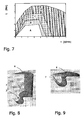
- FIG. 7 shows an exemplary division of the engine state space described by the engine load L and the engine speed n on the various operating modes described above, the exact course of the transition zones between the operating modes can be set individually depending on the engine and application.
- FIG. 8 shows a sector-shaped section of the combustion chamber at a position of the piston of about 82 ° before top dead center.
- the fuel droplets 7 a first, early fuel injection.
- the first fuel injection thus takes place between about 120 ° and about 60 ° before top dead center.
- the fuel is not injected into the piston bowl 3 but into the adjacent region where squeeze flow formation occurs.
- FIG. 9 shows in a representation accordingly FIG. 8 the second fuel injection.
- the piston is at this time at about 12 ° before top dead center.
- the second fuel injection 7 takes place between about 25 ° and 0 ° before top dead center and is preferably directed into the piston bowl 3.
- the described fuel injection strategy guarantees a well-mixed air-fuel mixture, which leads to low NOx and soot emissions.
- the distribution of the fuel mass to the individual fuel injections must be made according to the engine speed and the load conditions. For the example above the FIGS. 8 and 9 About 35% of the fuel is supplied in the first and 65% in the second fuel injection.
- the advantage of the (at least) two-phase fuel injection is the possibility of influencing the beginning of combustion by the time of the first injection in the above-mentioned time window.
- FIG. 10 shows in this regard the courses of heat emission as a function of the crankshaft angle for three different times of the first fuel injection. Surprisingly, the sooner the first fuel injection occurs, the later the bulk of heat is released. Preferably, therefore, such early fuel injections are made.
- the charge distribution in the cylinder is extremely homogeneous, with the described fuel injection strategy it is possible to influence the onset of combustion and thus obtain a suitable control parameter for the combustion noise and emissions.
Landscapes
- Engineering & Computer Science (AREA)
- Chemical & Material Sciences (AREA)
- Combustion & Propulsion (AREA)
- Mechanical Engineering (AREA)
- General Engineering & Computer Science (AREA)
- Electrical Control Of Air Or Fuel Supplied To Internal-Combustion Engine (AREA)
- Combustion Methods Of Internal-Combustion Engines (AREA)
- Output Control And Ontrol Of Special Type Engine (AREA)
Claims (13)
- Procédé pour faire fonctionner un moteur diesel à injection directe, comprenant les modes de fonctionnement suivants :A) Premier mode de fonctionnement A pour une faible charge du moteur (L) : combustion homogène du carburant injecté par au moins une injection de carburant pendant le temps de compression entre 180° et 0° avant le point mort haut et par recirculation des gaz d'échappement à un taux compris entre 40% et 70% ;B) Deuxième mode de fonctionnement B pour une charge moyenne du moteur (L) : combustion homogène d'environ 50% à 90% du carburant injecté, au moins une injection de carburant ayant lieu pendant le temps de compression entre 180°et 0° avant le point mort haut et une recirculation des gaz d'échappement ayant lieu à un taux compris entre 40% et 70%, ainsi qu'injection du carburant restant entre 0° et 40° après le point mort haut, le retard à l'allumage de la combustion homogène étant ajusté si grand que la formation du mélange homogène a lieu au moins en partie à proximité du point mort haut et que la diffusion de chaleur maximale a lieu après le point mort haut ;la quantité de carburant pour la combustion homogène étant injectée en deux phases au cours d'une injection préalable de carburant entre environ 120° à environ 60° avant le point mort haut et au cours d'une injection ultérieure entre environ 25° et environ 0° avant le point mort haut.
- Procédé selon la revendication 1,
caractérisé en ce que
l'injection de carburant a lieu pendant le temps de compression dans les deux modes de fonctionnement A et B pour une pression de carburant de 300 à 2000 bars. - Procédé selon la revendication 1 ou 2,
caractérisé en ce que
l'ajustement du retard à l'allumage est produit par un rapport de compression réduit. - Procédé selon au moins l'une quelconque des revendications 1 à 3,
caractérisé en ce que
l'ajustement du retard à l'allumage est produit par un refroidissement des gaz d'échappement recirculés. - Procédé selon au moins l'une quelconque des revendications 1 à 4,
caractérisé en ce que
l'ajustement du retard à l'allumage est produit par un écoulement guidé par les parois et/ou par la formation d'une cavité de piston (3). - Procédé selon au moins l'une quelconque des revendications 1 à 5,
caractérisé en ce
qu'il comprend un troisième mode de fonctionnement qui est mis en oeuvre de préférence pour une charge élevée et/ou pour une charge maximale, et qui comprend une combustion hétérogène avec au moins une injection de carburant à proximité du point mort haut. - Procédé selon au moins l'une quelconque des revendications 1 à 6,
caractérisé en ce que
l'injection préalable de carburant est orientée dans l'espace de compression situé au-dessus d'une cavité du piston (3). - Procédé selon au moins l'une quelconque des revendications 1 à 7,
caractérisé en ce que
l'injection de carburant ultérieure est orientée dans la cavité du piston (3). - Moteur diesel comprenant au moins un cylindre (2, 4) qui contient un piston (1) et au moins un injecteur de carburant (5), ainsi qu'une recirculation de gaz d'échappement et une commande de moteur,
caractérisé en ce que
la commande du moteur est réalisée de manière à mettre en oeuvre un procédé selon au moins l'une quelconque des revendications 1 à 8. - Moteur diesel selon la revendication 9,
caractérisé en ce que
l'injecteur de carburant (5) présente cinq à douze ouvertures de sortie (6) et peut produire un cône de pulvérisation (7) avec un angle d'ouverture d'environ 50° à environ 160°. - Moteur diesel selon la revendication 9 ou 10,
caractérisé en ce
qu'il possède un rapport de compression compris entre 12 et 18. - Moteur diesel selon au moins l'une quelconque des revendications 9 à 11,
caractérisé en ce que
le piston (1) présente une cavité de piston (3) dont le diamètre maximal (d) vaut environ 55% à environ 75% du diamètre du piston (D). - Moteur diesel selon au moins l'une quelconque des revendications 9 à 12,
caractérisé en ce que
le piston (1) présente une cavité de piston (3) dont la profondeur maximale (t) vaut environ 15% à environ 25% du diamètre du piston (D).
Priority Applications (2)
| Application Number | Priority Date | Filing Date | Title |
|---|---|---|---|
| EP03101845A EP1491740B1 (fr) | 2003-06-24 | 2003-06-24 | Procédé de fonctionnement d'un moteur Diesel |
| DE50309257T DE50309257D1 (de) | 2003-06-24 | 2003-06-24 | Verfahren zum Betrieb eines Dieselmotors |
Applications Claiming Priority (1)
| Application Number | Priority Date | Filing Date | Title |
|---|---|---|---|
| EP03101845A EP1491740B1 (fr) | 2003-06-24 | 2003-06-24 | Procédé de fonctionnement d'un moteur Diesel |
Publications (2)
| Publication Number | Publication Date |
|---|---|
| EP1491740A1 EP1491740A1 (fr) | 2004-12-29 |
| EP1491740B1 true EP1491740B1 (fr) | 2008-02-27 |
Family
ID=33395989
Family Applications (1)
| Application Number | Title | Priority Date | Filing Date |
|---|---|---|---|
| EP03101845A Expired - Lifetime EP1491740B1 (fr) | 2003-06-24 | 2003-06-24 | Procédé de fonctionnement d'un moteur Diesel |
Country Status (2)
| Country | Link |
|---|---|
| EP (1) | EP1491740B1 (fr) |
| DE (1) | DE50309257D1 (fr) |
Cited By (1)
| Publication number | Priority date | Publication date | Assignee | Title |
|---|---|---|---|---|
| DE102011121641B4 (de) * | 2011-01-05 | 2014-05-28 | Mazda Motor Corp. | Dieselmotor für ein Fahrzeug und Verfahren zum Regeln bzw. Steuern desselben |
Families Citing this family (4)
| Publication number | Priority date | Publication date | Assignee | Title |
|---|---|---|---|---|
| US7201137B2 (en) * | 2005-07-11 | 2007-04-10 | Caterpillar Inc | Mixed mode control method and engine using same |
| US7219649B2 (en) | 2005-08-10 | 2007-05-22 | Caterpillar Inc | Engine system and method of operating same over multiple engine load ranges |
| US11499496B2 (en) * | 2018-01-16 | 2022-11-15 | Caterpillar Inc. | Engine control system and method |
| CN113700569A (zh) * | 2021-07-27 | 2021-11-26 | 东风汽车集团股份有限公司 | 直喷发动机的喷油控制方法、装置、电子设备和存储介质 |
Family Cites Families (5)
| Publication number | Priority date | Publication date | Assignee | Title |
|---|---|---|---|---|
| JP3421059B2 (ja) * | 1998-02-23 | 2003-06-30 | カミンス エンジン カンパニー インコーポレイテッド | 最適燃焼コントロールを有する予混合チャージ圧縮点火エンジン |
| JP3549779B2 (ja) * | 1999-09-17 | 2004-08-04 | 日野自動車株式会社 | 内燃機関 |
| DE19953932C2 (de) * | 1999-11-10 | 2002-04-18 | Daimler Chrysler Ag | Verfahren zum Betrieb einer Hubkolbenbrennkraftmaschine |
| WO2001086128A2 (fr) * | 2000-05-08 | 2001-11-15 | Cummins, Inc. | Moteur a combustion interne fonctionnant en mode d'allumage par compression de charge premelangee avec injection de commande precoce, et son procede de fonctionnement |
| JP3893967B2 (ja) * | 2001-12-18 | 2007-03-14 | 日産自動車株式会社 | ディーゼルエンジンの制御装置 |
-
2003
- 2003-06-24 DE DE50309257T patent/DE50309257D1/de not_active Expired - Lifetime
- 2003-06-24 EP EP03101845A patent/EP1491740B1/fr not_active Expired - Lifetime
Cited By (1)
| Publication number | Priority date | Publication date | Assignee | Title |
|---|---|---|---|---|
| DE102011121641B4 (de) * | 2011-01-05 | 2014-05-28 | Mazda Motor Corp. | Dieselmotor für ein Fahrzeug und Verfahren zum Regeln bzw. Steuern desselben |
Also Published As
| Publication number | Publication date |
|---|---|
| DE50309257D1 (de) | 2008-04-10 |
| EP1491740A1 (fr) | 2004-12-29 |
Similar Documents
| Publication | Publication Date | Title |
|---|---|---|
| DE10213011B4 (de) | Selbstzündende Brennkraftmaschine | |
| EP1639251B1 (fr) | Moteur a combustion interne a auto-allumage | |
| EP1537320B1 (fr) | Procedes pour faire fonctionner un moteur a combustion interne a allumage commande | |
| DE602004012478T2 (de) | Vorrichtung und Verfahren zur Steuerung von Mehrfachfacheinspritzung und variablen Ventilsteuerzeiten in einer direkteinspritzenden Brennkraftmaschine | |
| DE10147529B4 (de) | Verfahren zum Betreiben einer mit selbstzündbarem Kraftstoff betriebenen Brennkraftmaschine | |
| DE10213025B4 (de) | Selbstzündende Brennkraftmaschine | |
| EP1537316B1 (fr) | Procede pour faire fonctionner un moteur a combustion interne a injection directe de carburant | |
| DE10048238B4 (de) | Verfahren zum Betrieb einer Dieselbrennkraftmaschine | |
| DE10348366B4 (de) | Verfahren zum Betreiben einer direkteinspritzenden Diesel-Brennkraftmaschine | |
| EP1639242B1 (fr) | Moteur a combustion interne a auto-allumage | |
| EP1180211B1 (fr) | Procede pour injecter du carburant et soupape d'injection permettant de mettre en oeuvre ledit procede | |
| DE10315149A1 (de) | Brennkraftmaschine mit Selbstzündung | |
| WO2005033496A1 (fr) | Procede de fonctionnement d'un moteur a combustion interne | |
| EP1039112A2 (fr) | Système d'alimentation de combustible pour un moteur à combustion interne à allumage commandé | |
| DE102012107714A1 (de) | Steuersystem für ein Verbrennungssystem | |
| EP1999350A1 (fr) | Procédé de combustion d'un moteur à combustion interne et moteur à combustion interne | |
| AT508578B1 (de) | Verfahren zum betreiben einer viertakt-brennkraftmaschine mit funkenzündung | |
| DE60217021T2 (de) | Verfahren zur Steuerung der Brennstoffeinspritzung einer Brennkraftmaschine mit Direkteinspritzung | |
| EP1703112B1 (fr) | Procédé de chauffage d'un catalyseur d'un moteur à combustion interne | |
| DE10354827A1 (de) | Brennstoffeinspritzsystem | |
| DE112006001836T5 (de) | Mischmodussteuerverfahren und Motor, der dieses verwendet | |
| EP1491740A1 (fr) | Procédé de fonctionnement d'un moteur Diesel | |
| EP2831400B1 (fr) | Procédé pour faire fonctionner un moteur à combustion interne | |
| DE102006027338A1 (de) | Dieselbrennkraftmaschine | |
| DE10359053A1 (de) | Verfahren zum Betrieb einer Brennkraftmaschine |
Legal Events
| Date | Code | Title | Description |
|---|---|---|---|
| PUAI | Public reference made under article 153(3) epc to a published international application that has entered the european phase |
Free format text: ORIGINAL CODE: 0009012 |
|
| AK | Designated contracting states |
Kind code of ref document: A1 Designated state(s): AT BE BG CH CY CZ DE DK EE ES FI FR GB GR HU IE IT LI LU MC NL PT RO SE SI SK TR |
|
| AX | Request for extension of the european patent |
Extension state: AL LT LV MK |
|
| 17P | Request for examination filed |
Effective date: 20050629 |
|
| AKX | Designation fees paid |
Designated state(s): DE FR GB |
|
| GRAP | Despatch of communication of intention to grant a patent |
Free format text: ORIGINAL CODE: EPIDOSNIGR1 |
|
| GRAS | Grant fee paid |
Free format text: ORIGINAL CODE: EPIDOSNIGR3 |
|
| GRAA | (expected) grant |
Free format text: ORIGINAL CODE: 0009210 |
|
| AK | Designated contracting states |
Kind code of ref document: B1 Designated state(s): DE FR GB |
|
| REG | Reference to a national code |
Ref country code: GB Ref legal event code: FG4D Free format text: NOT ENGLISH |
|
| REF | Corresponds to: |
Ref document number: 50309257 Country of ref document: DE Date of ref document: 20080410 Kind code of ref document: P |
|
| ET | Fr: translation filed | ||
| PLBE | No opposition filed within time limit |
Free format text: ORIGINAL CODE: 0009261 |
|
| STAA | Information on the status of an ep patent application or granted ep patent |
Free format text: STATUS: NO OPPOSITION FILED WITHIN TIME LIMIT |
|
| 26N | No opposition filed |
Effective date: 20081128 |
|
| REG | Reference to a national code |
Ref country code: FR Ref legal event code: PLFP Year of fee payment: 14 |
|
| REG | Reference to a national code |
Ref country code: FR Ref legal event code: PLFP Year of fee payment: 15 |
|
| REG | Reference to a national code |
Ref country code: FR Ref legal event code: PLFP Year of fee payment: 16 |
|
| PGFP | Annual fee paid to national office [announced via postgrant information from national office to epo] |
Ref country code: FR Payment date: 20190522 Year of fee payment: 17 |
|
| PGFP | Annual fee paid to national office [announced via postgrant information from national office to epo] |
Ref country code: GB Payment date: 20190524 Year of fee payment: 17 |
|
| GBPC | Gb: european patent ceased through non-payment of renewal fee |
Effective date: 20200624 |
|
| PG25 | Lapsed in a contracting state [announced via postgrant information from national office to epo] |
Ref country code: FR Free format text: LAPSE BECAUSE OF NON-PAYMENT OF DUE FEES Effective date: 20200630 Ref country code: GB Free format text: LAPSE BECAUSE OF NON-PAYMENT OF DUE FEES Effective date: 20200624 |
|
| PGFP | Annual fee paid to national office [announced via postgrant information from national office to epo] |
Ref country code: DE Payment date: 20220512 Year of fee payment: 20 |
|
| REG | Reference to a national code |
Ref country code: DE Ref legal event code: R071 Ref document number: 50309257 Country of ref document: DE |
|
| P01 | Opt-out of the competence of the unified patent court (upc) registered |
Effective date: 20230620 |