EP1322013A2 - Plastic arrangement for installation in concrete construction - Google Patents
Plastic arrangement for installation in concrete construction Download PDFInfo
- Publication number
- EP1322013A2 EP1322013A2 EP02022721A EP02022721A EP1322013A2 EP 1322013 A2 EP1322013 A2 EP 1322013A2 EP 02022721 A EP02022721 A EP 02022721A EP 02022721 A EP02022721 A EP 02022721A EP 1322013 A2 EP1322013 A2 EP 1322013A2
- Authority
- EP
- European Patent Office
- Prior art keywords
- arrangement according
- arrangement
- installation
- profile
- web
- Prior art date
- Legal status (The legal status is an assumption and is not a legal conclusion. Google has not performed a legal analysis and makes no representation as to the accuracy of the status listed.)
- Withdrawn
Links
Images



Classifications
-
- H—ELECTRICITY
- H02—GENERATION; CONVERSION OR DISTRIBUTION OF ELECTRIC POWER
- H02G—INSTALLATION OF ELECTRIC CABLES OR LINES, OR OF COMBINED OPTICAL AND ELECTRIC CABLES OR LINES
- H02G3/00—Installations of electric cables or lines or protective tubing therefor in or on buildings, equivalent structures or vehicles
- H02G3/02—Details
- H02G3/08—Distribution boxes; Connection or junction boxes
- H02G3/12—Distribution boxes; Connection or junction boxes for flush mounting
Definitions
- the invention relates to an arrangement Plastic for the concrete building installation correct arrangement and mounting of Installation parts, in particular electrotechnical installation parts, consisting of two supporting parts by two separable and in at least two different axial positions joinable spacers are connected, the spacers across across Arranged longitudinal axis of the arrangement complementary sliding connections are assembled, so that in particular lying concrete formwork a supporting part on the Formwork can be fastened or attached to it and the other support part in one of the thickness of the corresponding component to be concreted Distance from the formwork is arranged.
- Installation parts in particular electrotechnical installation parts, consisting of two supporting parts by two separable and in at least two different axial positions joinable spacers are connected, the spacers across across Arranged longitudinal axis of the arrangement complementary sliding connections are assembled, so that in particular lying concrete formwork a supporting part on the Formwork can be fastened or attached to it and the other support part in one of the thickness of the corresponding component to be concreted Distance from the formwork is arranged.
- Such an arrangement is from WO 98/53541 known.
- the spacers through complementary sliding connections with each other connectable, in which the one element a T-shaped groove and the other element a T-shaped bridge.
- Such Training is relatively complicated in the Shaping, especially if the corresponding parts molded from plastic become.
- these elements are also complicated to use because of Users pay close attention to the Must align fasteners and these must be positioned exactly to each other in order to Parts by sliding connection with each other to be able to connect.
- the invention has for its object a Arrangement of generic type to create the can be manufactured relatively easily and the is simple and precise to use.
- the invention proposes to achieve this object before that the first spacer by one of protruding tube profile with the first supporting part rectangular cross section is formed, which on two mutually parallel outer surfaces as Sliding fastener first serrations and that the second spacer by a protruding from the second support part Profile piece formed with a U-shaped cross section is which is lying on the inside of the thighs second serrations as sliding connection means having.
- the second supporting part which is in the Cross-section is U-shaped extremely stable and stable. Both parts can be made very easily from plastic be, with the appropriate serrations that the connecting means of the sliding connection manufacture in a simple manner through a relative uncomplicated plastic tool manufactured can be.
- the handling of such Arrangement is very simple, the User only the parts in the correct position feed each other and cross each other has to move. Finding the corresponding serrations and insertion into the serrations is simple to perform, even if at On site operation, the teeth are dirty are, a perfect postponement enables is because the open serrations when sliding open freed of adhering impurities become.
- the supporting parts a positioning aid formed because the second in the target mounting position Profile piece with a U-shaped cross section only in this way be pushed far onto the first supporting part can until the base of the U-shaped part the corresponding counter surface of the as Square profile trained tube profile is applied. This is an end stop formed by the user without further ado is to be found and complied with.
- the arrangement is chosen by the Room shape stable, so that when concreting occurring loads in the axial direction of the Spacers and also good in the torsion direction can be recorded without the Order is damaged.
- Toothings mesh almost without play, so that movements in the longitudinal direction of the Spacers are prevented.
- each latch is free End of an L-shaped, on a toothless one Wall of the tubular profile molded on the outside Web is formed.
- each non-resilient Holding nose by an L-shaped one toothless wall of the tubular profile outside molded rigid web is formed.
- Tooth-free wall formed on the legs of the the web carrying the latch is resilient is trained.
- each support part consists of one essentially flat plate, which is on the other Side facing away from the support part Connector and / or to a push button-like Connector has complementary locking holes, and that any attachable to the support member Installation part, e.g. in form of a Installation box or a magnetic holder, a surface matching the plate of the supporting part with snap-type connectors and / or Has snap holes, so that Installation part with the support part is pluggable.
- Profile piece on the outside over the legs and the base molded Has stiffening webs.
- an arrangement is made Plastic for the concrete building installation shown. It serves for the correct arrangement and mounting of installation parts 1, for example an installation box or like.
- the arrangement consists of two Support parts 2, 3 by two from each other separable and in at least two different axial positions spacers 4 and 5 that can be joined together are connected.
- the spacers 4, 5 are by arranged transversely to their longitudinal axis complementary sliding connections can be put together, so that mainly at horizontal concrete formwork a supporting part, for example 2, attachable to the formwork or can be applied to this and the other Support part, for example 3, in one of the thickness of the component to be concreted Distance from the formwork is arranged.
- the first spacer 4 is by one of the first supporting part 2 protruding tube profile rectangular cross section formed on two mutually parallel outer surfaces as Sliding connection means first teeth 6 having.
- the second spacer 5 is through a protruding from the second support part 3 Profile piece with a U-shaped cross section formed, which lies on the inside Legs as a second sliding connecting means Teeth 7 has.
- the serrations 6, 7 are shaped so that they have no undercut and by im Cross section of approximately rectangular rod shapes are formed. In the assembly target position, the for example, shown in Figure 2 the serrations 6, 7 into one another almost without play, so that movements in the longitudinal direction of the Spacers 4, 5 are prevented.
- the toothless side surfaces of the Pipe profile and the base surface of the U-shaped Profile pieces each have large areas Wall recesses 8, 9 so that when Concreting process also in the concrete mass the spacer 4 enclosed cavity can flow in.
- Each latch 10 is approximately at the free end L-shaped, on a toothless wall of the Pipe profile of the spacer 4 outside molded web formed. Not everyone resilient retaining lug 12 is also on an L-shaped, on a toothless wall of the spacer 4 molded on the outside. Here the web is stiff trained, whereas the web at the Lugs 10 is resilient.
- Each support part 2 or 3 consists of a Essential flat plate, which at its the each other side facing away from the supporting part Has push button-like connector 13.
- each on the corresponding support part 2 or 3 attachable installation part 1 has one parallel to the surface of the supporting part 2 or 3 Corresponding locking holes so that the installation part 1 with the respective Support part 2 or 3 plug-in and in Plug connection snapped like a push button is held.
- the second also shows the stiffening Spacer 5, which as a U-shaped Profile piece is formed over the legs and the base outside Stiffening webs 15.
- the invention provides an arrangement for Available that are relatively easy to manufacture handle is with the impurities Do not bother handling when a noticeable Target mounting position is adjustable, which too is secured and extremely stable and is also torsionally stable.
- the invention is not based on that Embodiment limited, but in The scope of the disclosure is often variable.
Landscapes
- Engineering & Computer Science (AREA)
- Architecture (AREA)
- Civil Engineering (AREA)
- Structural Engineering (AREA)
- Forms Removed On Construction Sites Or Auxiliary Members Thereof (AREA)
- Mutual Connection Of Rods And Tubes (AREA)
Abstract
Um eine Anordnung aus Kunststoff für die
Betonbauinstallation zur lagerichtigen Anordnung und
Halterung von Installationsteilen (1), bestehend aus
zwei Tragteilen (2,3) mit zwei in unterschiedlichen
axialen Positionen schiebeverbindbaren Abstandshaltern
(4,5) zu schaffen, die relativ einfach gefertigt werden
kann und die einfach sowie präzise zu handhaben ist,
wird vorgeschlagen, dass der erste Abstandhalter (4)
durch ein von dem ersten Tragteil (2) abragendes,
rechteckiges Rohrprofil gebildet ist, welches auf
Außenflächen als Schiebeverbindungsmittel erste
Zahnungen (6) aufweist, und dass der zweite
Abstandhalter (5) durch ein vom zweiten Tragteil (3)
abragendes, U-förmiges Profilstück gebildet ist,
welches innen auf den Schenkeln als
Schiebeverbindungsmittel zweite Zahnungen (7) aufweist.
Description
Die Erfindung betrifft eine Anordnung aus Kunststoff für die Betonbauinstallation zur lagerichtigen Anordnung und Halterung von Installationsteilen, insbesondere elektrotechnischen Installationsteilen, bestehend aus zwei Tragteilen, die durch zwei trennbare und in mindestens zwei unterschiedlichen axialen Positionen fest zusammenfügbare Abstandshalter verbunden sind, wobei die Abstandshalter über quer zur Längsachse der Anordnung angeordnete komplementäre Schiebeverbindungen zusammensetzbar sind, so dass insbesondere bei liegender Betonbauschalung ein Tragteil an der Schalung befestigbar bzw. an diese anlegbar ist und das andere Tragteil in einem der Dicke des zu betonierenden Bauteiles entsprechenden Abstand von der Schalung angeordnet ist. The invention relates to an arrangement Plastic for the concrete building installation correct arrangement and mounting of Installation parts, in particular electrotechnical installation parts, consisting of two supporting parts by two separable and in at least two different axial positions joinable spacers are connected, the spacers across across Arranged longitudinal axis of the arrangement complementary sliding connections are assembled, so that in particular lying concrete formwork a supporting part on the Formwork can be fastened or attached to it and the other support part in one of the thickness of the corresponding component to be concreted Distance from the formwork is arranged.
Eine derartige Anordnung ist aus der WO 98/53541 bekannt. Bei der bekannten Anordnung, die insbesondere dafür bestimmt ist, zwischen zwei Schaltafeln eingespannt zu werden, wird insbesondere die komplizierte Form der Abstandhalter als nachteilig angesehen. Hierbei sind nämlich die Abstandhalter durch komplementäre Schiebeverbindungen miteinander verbindbar, bei denen das eine Element aus einer T-förmigen Nut und das andere Element aus einem T-förmigen Steg besteht. Eine solche Ausbildung ist relativ kompliziert in der Formgebung, insbesondere wenn die entsprechenden Teile aus Kunststoff geformt werden. Darüber hinaus sind diese Element auch kompliziert in der Handhabung, weil der Benutzer genaues Augenmerk auf die Verbindungselemente richten muss und diese exakt zueinander positionieren muss, um die Teile durch Schiebeverbindung miteinander verbinden zu können. Die exakte Passung der Teile zueinander ist schwierig einstellbar, weil schon bei geringen Fertigungstoleranzen der Kunststoffteile kein sicherer Sitz zu erreichen ist und bei exakt genauer Positionierung ein Klemmeffekt auftritt, so dass die Teile nur schwierig miteinander schiebeverbindbar sind. Zudem ist beim Zusammenschieben der Teile keine exakte Positionierung der Teile zueinander möglich, da für die Schiebebewegung kein Endanschlag gebildet ist. Such an arrangement is from WO 98/53541 known. In the known arrangement, which is intended in particular between two formwork panels will be clamped especially the complicated shape of the Spacers viewed as disadvantageous. in this connection are the spacers through complementary sliding connections with each other connectable, in which the one element a T-shaped groove and the other element a T-shaped bridge. Such Training is relatively complicated in the Shaping, especially if the corresponding parts molded from plastic become. In addition, these elements are also complicated to use because of Users pay close attention to the Must align fasteners and these must be positioned exactly to each other in order to Parts by sliding connection with each other to be able to connect. The exact fit of the Parts to each other is difficult to adjust, because even with small manufacturing tolerances the plastic parts do not fit securely is achieved and with exact accuracy Positioning a clamping effect occurs, so that the parts are difficult with each other are connectable. In addition, the Pushing the parts together no exact Positioning of the parts to each other possible because no end stop for the sliding movement is formed.
Ausgehend von diesem Stand der Technik liegt der Erfindung die Aufgabe zugrunde, eine Anordnung gattungsgemäßer Art zu schaffen, die relativ einfach gefertigt werden kann und die einfach sowie präzise zu handhaben ist.Based on this state of the art the invention has for its object a Arrangement of generic type to create the can be manufactured relatively easily and the is simple and precise to use.
Zur Lösung dieser Aufgabe schlägt die Erfindung vor, dass der erste Abstandhalter durch ein von dem ersten Tragteil abragendes Rohrprofil mit rechteckigem Querschnitt gebildet ist, welches auf zwei zueinander parallelen Außenflächen als Schiebeverbindungsmittel erste Zahnungen aufweist, und dass der zweite Abstandhalter durch ein vom zweiten Tragteil abragendes Profilstück mit U-förmigem Querschnitt gebildet ist, welches innen liegend auf den Schenkeln als Schiebeverbindungsmittel zweite Zahnungen aufweist.The invention proposes to achieve this object before that the first spacer by one of protruding tube profile with the first supporting part rectangular cross section is formed, which on two mutually parallel outer surfaces as Sliding fastener first serrations and that the second spacer by a protruding from the second support part Profile piece formed with a U-shaped cross section is which is lying on the inside of the thighs second serrations as sliding connection means having.
Durch das als Vierkantprofil ausgebildete Rohrprofil des ersten Tragteiles wird ein sehr steifes und stabiles Stützelement geschaffen. Auch das zweite Tragteil, welches im Querschnitt U-förmig ausgebildet ist, ist äußerst formstabil und formhaltig. Beide Teile können sehr einfach aus Kunststoff gefertigt werden, wobei die entsprechenden Zahnungen, die die Verbindungsmittel der Schiebeverbindung herstellen in einfacher Weise durch ein relativ unkompliziertes Kunststoffwerkzeug gefertigt werden können. Die Handhabung einer solchen Anordnung ist denkbar einfach, wobei der Benutzer lediglich die Teile lagerichtig einander zuführen und quer zueinander verschieben muss. Das Auffinden der entsprechenden Zahnungen und das Einschieben in die Zahnungen ist in einfacher Weise durchzuführen, wobei selbst dann, wenn beim Baustellenbetrieb die Zahnungen verschmutzt sind, ein einwandfreies Aufschieben ermöglicht ist, da die offenen Zahnungen beim Aufschieben von anhaftenden Verunreinigungen befreit werden. Zudem ist durch die gewählte Raumform der Tragteile eine Positionierungshilfe gebildet, da in der Soll-Montagelage das zweite Profilstück mit U-förmigen Querschnitt nur so weit auf das erste Tragteil aufgeschoben werden kann, bis die Basis des U-förmigen Teiles an der entsprechenden Gegenfläche des als Vierkantprofil ausgebildeten Rohrprofils anliegt. Hierdurch ist ein Endanschlag gebildet, der vom Benutzer ohne weiteres aufzufinden und einzuhalten ist.Through the trained as a square profile Pipe profile of the first supporting part becomes a very stiff and stable support element created. Also the second supporting part, which is in the Cross-section is U-shaped extremely stable and stable. Both parts can be made very easily from plastic be, with the appropriate serrations that the connecting means of the sliding connection manufacture in a simple manner through a relative uncomplicated plastic tool manufactured can be. The handling of such Arrangement is very simple, the User only the parts in the correct position feed each other and cross each other has to move. Finding the corresponding serrations and insertion into the serrations is simple to perform, even if at On site operation, the teeth are dirty are, a perfect postponement enables is because the open serrations when sliding open freed of adhering impurities become. In addition, due to the selected spatial shape the supporting parts a positioning aid formed because the second in the target mounting position Profile piece with a U-shaped cross section only in this way be pushed far onto the first supporting part can until the base of the U-shaped part the corresponding counter surface of the as Square profile trained tube profile is applied. This is an end stop formed by the user without further ado is to be found and complied with.
Zudem ist die Anordnung durch die gewählte Raumform stabil, so dass die beim Betonieren auftretenden Lasten in Achsrichtung der Abstandshalter und auch in Torsionsrichtung gut aufgenommen werden könne, ohne dass die Anordnung Schaden nimmt. In addition, the arrangement is chosen by the Room shape stable, so that when concreting occurring loads in the axial direction of the Spacers and also good in the torsion direction can be recorded without the Order is damaged.
Um die Fertigung weiter zu vereinfachen ist zudem vorgesehen, dass die Zahnungen keinen Hinterschnitt aufweisen.To further simplify production also provided that the serrations none Have an undercut.
Besonders bevorzugt ist aus dem gleichen Grunde vorgesehen, dass die Zahnungen durch im Querschnitt rechteckige Stabformen gebildet sind.Is particularly preferred for the same reason provided that the teeth by im Cross-section rectangular rod shapes formed are.
Zudem ist bevorzugt vorgesehen, dass die Zahnungen nahezu spielfrei ineinander greifen, so dass Bewegungen in Längsrichtung der Abstandhalter unterbunden sind.In addition, it is preferably provided that the Toothings mesh almost without play, so that movements in the longitudinal direction of the Spacers are prevented.
Um sicherzustellen, dass beim Betonieren auch Betonmaterial in die von dem Rohrprofil umschlossenen Räume eindringen kann, ist vorgesehen, dass mindestens die zahnungsfreien Seitenflächen des Rohrprofils und/oder die Basisfläche des Profilstücks großflächige Wandungsausnehmungen aufweisen.To make sure that when concreting too Concrete material in the from the pipe profile enclosed spaces can penetrate is provided that at least the toothless Side faces of the tubular profile and / or the Base area of the profile piece large area Have wall recesses.
Um einen besonders sicheren Halt der Teile aneinander in der Montagesollposition zu gewährleisten und zudem eine Montagehilfe für den Benutzer zur Verfügung zu stellen, wobei zudem auch eine äußerst hohe Torsionsfestigkeit des zusammengesetzten Elementes sichergestellt ist, wird vorgeschlagen, dass am in Einschubrichtung des Profilstückes hinten liegenden Wandungsbereich des Rohrprofils federnde Rastnasen, die bei aufgeschobenem Profilstück jeweils eine der an beiden freien Schenkelenden des Profilstückes vorgesehenen Rastleisten rastend übergreift, sowie nicht federnde Haltenasen vorgesehen ist, die die Rastleisten in der Einschubposition übergreifen.For a particularly secure hold of the parts to each other in the target assembly position guarantee and also an assembly aid for to provide the user, whereby also an extremely high torsional strength of the composite element ensured it is suggested that on in Direction of insertion of the profile piece at the rear lying wall area of the tubular profile resilient locking lugs, when pushed open Profile piece one of the two free Provided leg ends of the profile piece Snap bars overlaps, and not resilient retaining lugs is provided, which Locking strips in the insertion position spread.
Beim Einschieben des im Querschnitt U-förmigen Teiles auf das im Querschnitt rechteckige Teil federn die Rastnasen in Endposition geringfügig auf, so dass die entsprechende Rastleiste des anderen Profilstückes übergriffen ist und ein sicherer Sitz gebildet ist. Um sicherzustellen, dass bei eventueller tordierenden Bewegung der Teile zueinander dieser Rastsitz nicht aufgehoben wird, sind zusätzlich die nicht federnden Haltenasen vorgesehen, die die entsprechenden Rastleisten des aufgeschobenen Stücks in der Einschubposition übergreifen und somit bei einer tordierenden Bewegung der Teile zueinander das Ausrasten der Rastverbindungsmittel verhindert.When inserting the U-shaped cross section Part on the part with a rectangular cross section spring slightly in the end position on so that the corresponding locking bar of the other profile piece is overlapped and a secure fit is formed. To ensure, that in the event of any twisting movement of the Do not share this rest seat with each other are also not canceled resilient retaining lugs provided that the corresponding locking bars of the pushed Overlap in the insertion position and thus with a twisting movement of the parts to each other the disengagement of the Locking connection means prevented.
Besonders bevorzugt ist zur Verbesserung der Positionslagesicherung vorgesehen, dass jeweils paarweise zwei federnde Rastnasen und zwischen diesen eine nicht federnde Haltenase eng benachbart nebeneinander vorgesehen sind.Is particularly preferred to improve Positional position provided that each in pairs two resilient locking lugs and between this a non-resilient holding nose tight are provided adjacent to each other.
Eine besonders bevorzugte Weiterbildung wird darin gesehen, dass jede Rastnase am freien Ende eines L-förmigen, an einer zahnungsfreien Wandung des Rohrprofils außen angeformten Steges ausgebildet ist.A particularly preferred further training is seen in that each latch is free End of an L-shaped, on a toothless one Wall of the tubular profile molded on the outside Web is formed.
Zudem ist vorgesehen, dass jede nicht federnde Haltenase durch einen L-förmigen, an einer zahnungsfreien Wandung des Rohrprofils außen angeformten steifen Steg gebildet ist.It is also envisaged that each non-resilient Holding nose by an L-shaped one toothless wall of the tubular profile outside molded rigid web is formed.
Um die Stabilität der nicht federnden Haltenase noch zu verbessern ist vorgesehen, dass der Steg durch eine in Steglängsrichtung verlaufende, außenseitig des Steges angeformte Rippe versteift ist.For the stability of the non-resilient retaining lug it is envisaged that the Bridge through one in the longitudinal direction of the bridge running, molded on the outside of the web Rib is stiffened.
Um die Federung der federnden Rastnase zu verbessern ist vorgesehen, dass der an der zahnungsfreien Wandung angeformte Schenkel des die Rastnase tragenden Steges federnd ausgebildet ist.To the suspension of the resilient latch It is envisaged that the Tooth-free wall formed on the legs of the the web carrying the latch is resilient is trained.
Eine besonders bevorzugte Weiterbildung, die auch bei herkömmlichen Anordnungen gemäß Stand der Technik vorteilhaft ist, besteht darin, dass jedes Tragteil aus einer im wesentlichen ebenen Platte besteht, die an ihrer dem anderen Tragteil abgewandten Seite druckknopfartige Verbinder und/oder zu einem druckknopfartigen Verbinder komplementäre Rastlochungen aufweist, und dass jedes an dem Tragteil befestigbare Installationsteil, z.B. in Form einer Installationsdose oder eines Magnethalters, eine zur Platte des Tragteils passende Fläche mit druckknopfartigen Verbindern und/oder Rastlochungen aufweist, so dass das Installationsteil mit dem Tragteil steckverbindbar ist.A particularly preferred training that even with conventional arrangements according to the state technology is advantageous is that each support part consists of one essentially flat plate, which is on the other Side facing away from the support part Connector and / or to a push button-like Connector has complementary locking holes, and that any attachable to the support member Installation part, e.g. in form of a Installation box or a magnetic holder, a surface matching the plate of the supporting part with snap-type connectors and / or Has snap holes, so that Installation part with the support part is pluggable.
Gemäß dieser Anordnung ist es in einfacher Weise möglich, die lediglich eine endseitige Platte aufweisenden Tragteile jeweils mit entsprechenden Installationsteilen, beispielsweise einer Installationsdose zu bestücken, indem diese lediglich aufgesteckt und durch die druckknopfartige Verbindung aufgerastet wird. Die Teile sind so in einfacher Weise miteinander zu verbinden, wobei der Benutzer die Wahlmöglichkeit hat, die entsprechenden Tragteile mit unterschiedlichen Installationsteilen zu bestücken. Dies vermindert sowohl den Fertigungsaufwand als auch den Lagerhaltungsaufwand, da die gleichen Trageteile für die Anordnung und Befestigung unterschiedlichster Installationsteile geeignet und bestimmt sind.According to this arrangement, it is easier Way possible that only one end Plate bearing parts with each corresponding installation parts, for example an installation box equip by simply plugging them on and through the push button-like connection is snapped on. The parts are so in easy way to connect with each other the user has the choice that corresponding supporting parts with different To equip installation parts. This reduces both the manufacturing effort and also the inventory costs, since the same Carrying parts for arrangement and fastening suitable for a wide variety of installation parts and are determined.
Um eine weitere Stabilisierung der Anordnung zu gewährleisten ist zudem vorgesehen, dass das Profilstück außenseitig über die Schenkel und die Basis verlaufende, angeformte Versteifungsstege aufweist.To further stabilize the arrangement It is also envisaged that Profile piece on the outside over the legs and the base, molded Has stiffening webs.
Ausführungsbeispiele der Erfindung sind in der Zeichnung dargestellt und im Folgenden näher beschrieben. Embodiments of the invention are in the Drawing shown and below in more detail described.
Es zeigt:
- Figur 1
- eine erste Anordnung in noch nicht zusammengeschobener Lage;
Figur 2- desgleichen in der Montagesolllage;
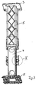
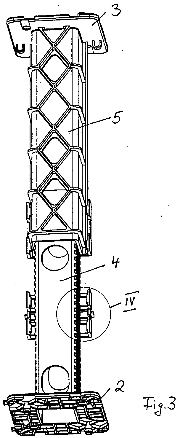
Figur 3- desgleichen in einer anderen Position;
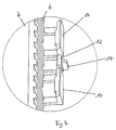
Figur 4- die Einzelheit IV der
Figur 3 in vergrößertem Maßstab; Figur 5- die Anordnung gemäß
Figur 2 mit angeordnetem Installationsteil; Figur 6- desgleichen in Position gemäß
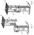
Figur 3; Figur 7 und 8- eine Variante in der Ansicht gemäß Figur 1 und 2.
- Figure 1
- a first arrangement in a position not yet pushed together;
- Figure 2
- likewise in the target assembly position;
- Figure 3
- likewise in a different position;
- Figure 4
- the detail IV of Figure 3 on an enlarged scale;
- Figure 5
- the arrangement of Figure 2 with the installation part arranged;
- Figure 6
- likewise in the position according to FIG. 3;
- Figures 7 and 8
- a variant in the view of Figures 1 and 2.
In der Zeichnung ist eine Anordnung aus
Kunststoff für die Betonbauinstallation
gezeigt. Sie dient zur lagerichtigen Anordnung
und Halterung von Installationsteilen 1,
beispielsweise einer Installationsdose oder
dergleichen. Die Anordnung besteht aus zwei
Tragteilen 2, 3, die durch zwei voneinander
trennbare und in mindestens zwei
unterschiedlichen axialen Positionen fest
zusammenfügbare Abstandshalter 4 bzw. 5
verbunden sind. Die Abstandshalter 4, 5 sind
durch quer zu ihrer Längsachse angeordnete
komplementäre Schiebeverbindungen
zusammensetzbar, so dass vornehmlich bei
liegender Betonbauschalung ein Tragteil,
beispielsweise 2, an der Schalung befestigbar
bzw. an diese anlegbar ist und das andere
Tragteil, beispielsweise 3, in einem der Dicke
des zu betonierenden Bauteiles entsprechenden
Abstand von der Schalung angeordnet ist.In the drawing an arrangement is made
Plastic for the concrete building installation
shown. It serves for the correct arrangement
and mounting of installation parts 1,
for example an installation box or
like. The arrangement consists of two
Der erste Abstandhalter 4 ist durch ein von dem
ersten Tragteil 2 abragendes Rohrprofil mit
rechteckigem Querschnitt gebildet, welches auf
zwei zueinander parallelen Außenflächen als
Schiebeverbindungsmittel erste Zahnungen 6
aufweist. Der zweite Abstandhalter 5 ist durch
ein vom zweiten Tragteil 3 abragendes
Profilstück mit U-förmigem Querschnitt
gebildet, welches innen liegend auf den
Schenkeln als Schiebeverbindungsmittel zweite
Zahnungen 7 aufweist.The
Die Zahnungen 6, 7 sind so geformt, dass sie
keinen Hinterschnitt aufweisen und durch im
Querschnitt etwa rechteckige Stabformen
gebildet sind. In der Montagesollposition, die
beispielsweise in Figur 2 gezeigt ist, greifen
die Zahnungen 6, 7 nahezu spielfrei ineinander,
so dass Bewegungen in Längsrichtung der
Abstandhalter 4, 5 unterbunden sind. The
Die zahnungsfreien Seitenflächen des
Rohrprofils und die Basisfläche des U-förmigen
Profilstücks weisen jeweils großflächige
Wandungsausnehmungen 8, 9 auf, so dass beim
Betonierungsvorgang Betonmasse auch in den von
dem Abstandhalter 4 umschlossenen Hohlraum
einfließen kann.The toothless side surfaces of the
Pipe profile and the base surface of the U-shaped
Profile pieces each have large areas
Wall recesses 8, 9 so that when
Concreting process also in the concrete mass
the
Wie insbesondere in der Zeichnungsfigur 4
verdeutlicht, sind am in Einschubrichtung des
als U-förmiges Profilstück ausgebildeten
Abstandhalters 5 hinten liegenden
Wandungsbereich des Rohrprofils des
Abstandhalters 4 federnde Rastnasen 10
vorgesehen, die bei aufgeschobenem Profilstück
(Abstandhalter 5) jeweils eine der an beiden
freien Schenkelenden des Profilstückes
vorgesehenen Randleisten 11 übergreift. Ferner
ist eine nicht federnde Haltenase 12
vorgesehen, die die Rastleiste 11 in der
Einschubposition übergreift. Vorzugsweise ist
dabei jeweils die paarweise Anordnung von zwei
federnden Rastnasen 10 und zwischen diesen eine
nicht federnde Haltenase 12 eng benachbart
nebeneinander vorgesehen, wie in Figur 4
verdeutlicht ist. Hierdurch wird einerseits
sichergestellt, dass beim Einschieben des
Abstandhalters 5 auf den Abstandhalter 4 eine
federnde Rastung im Bereich der Teile 10, 11
erfolgt, wobei durch die Teile 12 verhindert
wird, dass die Schenkel des U-förmigen
Abstandhalters 5 sich aufbiegen, wenn eine
tordierende Belastung um die Längsachse der
Anordnung aufgebracht wird.As in particular in the drawing figure 4
are shown in the insertion direction of the
trained as a U-shaped
Jede Rastnase 10 ist am freien Ende eines etwa
L-förmigen, an einer zahnungsfreien Wandung des
Rohrprofils des Abstandhalters 4 außen
angeformten Steges ausgebildet. Jede nicht
federnde Haltenase 12 ist ebenfalls an einem L-förmigen,
an einer zahnungsfreien Wandung des
als Rohrprofil ausgebildeten Abstandhalters 4
außen angeformt. Hierbei ist der Steg steif
ausgebildet, wohingegen der Steg bei den
Rastnasen 10 federnd ausgebildet ist.Each
Jedes Tragteil 2 bzw. 3 besteht aus einer im
Wesentliche ebenen Platte, die an ihrer dem
jeweils anderen Tragteil abgewandten Seite
druckknopfartige Verbinder 13 aufweist. Jedes
an dem entsprechenden Tragteil 2 bzw. 3
befestigbare Installationsteil 1 weist an einer
zur Fläche des Tragteiles 2 bzw. 3 parallelen
Fläche entsprechende Rastlochungen auf, so dass
das Installationsteil 1 mit dem jeweiligen
Tragteil 2 oder 3 steckverbindbar und in
Steckverbindung druckknopfartig gerastet
gehalten ist.Each
Zur Verstärkung des Steges der nicht federnden
Haltenase 12 ist dieser noch außenseitig mit
einer Rippe 14 versehen. To reinforce the web of the
Zur Versteifung weist ferner der zweite
Abstandhalter 5, welcher als U-förmiges
Profilstück ausgebildet ist, über die Schenkel
und die Basis außen verlaufende
Versteifungsstege 15 auf.The second also shows the
Die Erfindung stellt eine Anordnung zur Verfügung, die relativ einfach zu fertigen zu handhaben ist, bei der Verunreinigungen die Handhabung nicht stören, bei der eine merkbare Sollmontageposition einstellbar ist, die auch lagegesichert ist und die äußerst stabil und auch torsionsstabil ist.The invention provides an arrangement for Available that are relatively easy to manufacture handle is with the impurities Do not bother handling when a noticeable Target mounting position is adjustable, which too is secured and extremely stable and is also torsionally stable.
Die Erfindung ist nicht auf das Ausführungsbeispiel beschränkt, sondern im Rahmen der Offenbarung vielfach variabel.The invention is not based on that Embodiment limited, but in The scope of the disclosure is often variable.
Alle neuen, in der Beschreibung und/oder Zeichnung offenbarten Einzel- und Kombinationsmerkmale werden als erfindungswesentlich angesehen.All new, in the description and / or Drawing disclosed single and Combination features are as viewed essential to the invention.
Claims (13)
Applications Claiming Priority (2)
| Application Number | Priority Date | Filing Date | Title |
|---|---|---|---|
| DE10161172 | 2001-12-13 | ||
| DE10161172A DE10161172B4 (en) | 2001-12-13 | 2001-12-13 | Plastic arrangement for concrete building installation |
Publications (2)
| Publication Number | Publication Date |
|---|---|
| EP1322013A2 true EP1322013A2 (en) | 2003-06-25 |
| EP1322013A3 EP1322013A3 (en) | 2004-10-06 |
Family
ID=7709018
Family Applications (1)
| Application Number | Title | Priority Date | Filing Date |
|---|---|---|---|
| EP02022721A Withdrawn EP1322013A3 (en) | 2001-12-13 | 2002-10-11 | Plastic arrangement for installation in concrete construction |
Country Status (2)
| Country | Link |
|---|---|
| EP (1) | EP1322013A3 (en) |
| DE (1) | DE10161172B4 (en) |
Cited By (1)
| Publication number | Priority date | Publication date | Assignee | Title |
|---|---|---|---|---|
| EP2525459A3 (en) * | 2011-05-20 | 2013-12-25 | Agro Ag | Fixing for device holder |
Family Cites Families (1)
| Publication number | Priority date | Publication date | Assignee | Title |
|---|---|---|---|---|
| FR2763755B1 (en) * | 1997-05-22 | 1999-08-06 | Capri Codec Sa | ADJUSTABLE PLASTIC ASSEMBLY FOR HOLDING ELEMENTS SUCH AS ELECTRICAL EQUIPMENT BOXES BETWEEN BANCHES |
-
2001
- 2001-12-13 DE DE10161172A patent/DE10161172B4/en not_active Expired - Lifetime
-
2002
- 2002-10-11 EP EP02022721A patent/EP1322013A3/en not_active Withdrawn
Cited By (1)
| Publication number | Priority date | Publication date | Assignee | Title |
|---|---|---|---|---|
| EP2525459A3 (en) * | 2011-05-20 | 2013-12-25 | Agro Ag | Fixing for device holder |
Also Published As
| Publication number | Publication date |
|---|---|
| DE10161172B4 (en) | 2004-07-29 |
| DE10161172A1 (en) | 2003-07-03 |
| EP1322013A3 (en) | 2004-10-06 |
Similar Documents
| Publication | Publication Date | Title |
|---|---|---|
| DE2941008C2 (en) | frame | |
| EP0298225B1 (en) | Tower with various levels for displaying goods | |
| DE3533134C2 (en) | Coupling piece | |
| DE102005035702A1 (en) | Plate and carrier system for construction toys | |
| DE2324697A1 (en) | DISASSEMBLY ITEM, IN PARTICULAR FURNITURE, AND INDIVIDUAL COMPONENTS FOR ASSEMBLING THE ITEM | |
| DE2926976C2 (en) | Body that can be assembled from individual elements | |
| DE4421398C2 (en) | Fitting for connecting components | |
| EP3421691B1 (en) | Modular locking cylinder | |
| DE202010010620U1 (en) | ground cover | |
| DE102014218466B4 (en) | Frame system | |
| EP1122359A2 (en) | Screen and method for manufacturing the same | |
| EP1322013A2 (en) | Plastic arrangement for installation in concrete construction | |
| EP0018658A2 (en) | Linear,plane or spatial structure and hinge joint for such a structure | |
| DE2300532C2 (en) | Thermally insulating composite profile for window frames, door frames or the like | |
| DE102016004917A1 (en) | Fitting for a window, a door or the like | |
| DE20120166U1 (en) | Plastic arrangement for electrical connections in concrete installations has two carrier sections which can interlock with a push fit | |
| EP0307628B2 (en) | Grit-like framework with bars and nodes | |
| DE2435359B2 (en) | Detachable pin fastening of door handles that can be adjusted to different door thicknesses | |
| DE2721541C3 (en) | Grid ceiling | |
| EP1580341B1 (en) | Connecting element for a profile construction and profile construction | |
| DE10140878B4 (en) | Connection device for a wood-post-transom connection | |
| DE4136509A1 (en) | LIMBS RATIO, ESPECIALLY FROM PLASTIC | |
| DE3729664A1 (en) | Frame construction comprising profile rails and crossmember elements connecting these, in particular for constructing a fair stand | |
| EP0007006A1 (en) | Grating for forming duckboards or footscrapers | |
| EP2537570A2 (en) | Pocket filter |
Legal Events
| Date | Code | Title | Description |
|---|---|---|---|
| PUAI | Public reference made under article 153(3) epc to a published international application that has entered the european phase |
Free format text: ORIGINAL CODE: 0009012 |
|
| AK | Designated contracting states |
Designated state(s): AT BE BG CH CY CZ DE DK EE ES FI FR GB GR IE IT LI LU MC NL PT SE SK TR |
|
| AX | Request for extension of the european patent |
Extension state: AL LT LV MK RO SI |
|
| PUAL | Search report despatched |
Free format text: ORIGINAL CODE: 0009013 |
|
| AK | Designated contracting states |
Kind code of ref document: A3 Designated state(s): AT BE BG CH CY CZ DE DK EE ES FI FR GB GR IE IT LI LU MC NL PT SE SK TR |
|
| AX | Request for extension of the european patent |
Extension state: AL LT LV MK RO SI |
|
| 17P | Request for examination filed |
Effective date: 20041022 |
|
| AKX | Designation fees paid |
Designated state(s): AT BE BG CH CY CZ DE DK EE ES FI FR GB GR IE IT LI LU MC NL PT SE SK TR |
|
| GRAP | Despatch of communication of intention to grant a patent |
Free format text: ORIGINAL CODE: EPIDOSNIGR1 |
|
| STAA | Information on the status of an ep patent application or granted ep patent |
Free format text: STATUS: THE APPLICATION IS DEEMED TO BE WITHDRAWN |
|
| 18D | Application deemed to be withdrawn |
Effective date: 20070411 |