EP1322013A2 - Dispositif en plastique pour installation dans une construction en beton - Google Patents
Dispositif en plastique pour installation dans une construction en beton Download PDFInfo
- Publication number
- EP1322013A2 EP1322013A2 EP02022721A EP02022721A EP1322013A2 EP 1322013 A2 EP1322013 A2 EP 1322013A2 EP 02022721 A EP02022721 A EP 02022721A EP 02022721 A EP02022721 A EP 02022721A EP 1322013 A2 EP1322013 A2 EP 1322013A2
- Authority
- EP
- European Patent Office
- Prior art keywords
- arrangement according
- arrangement
- installation
- profile
- web
- Prior art date
- Legal status (The legal status is an assumption and is not a legal conclusion. Google has not performed a legal analysis and makes no representation as to the accuracy of the status listed.)
- Withdrawn
Links
Images


Classifications
-
- H—ELECTRICITY
- H02—GENERATION; CONVERSION OR DISTRIBUTION OF ELECTRIC POWER
- H02G—INSTALLATION OF ELECTRIC CABLES OR LINES, OR OF COMBINED OPTICAL AND ELECTRIC CABLES OR LINES
- H02G3/00—Installations of electric cables or lines or protective tubing therefor in or on buildings, equivalent structures or vehicles
- H02G3/02—Details
- H02G3/08—Distribution boxes; Connection or junction boxes
- H02G3/12—Distribution boxes; Connection or junction boxes for flush mounting
Definitions
- the invention relates to an arrangement Plastic for the concrete building installation correct arrangement and mounting of Installation parts, in particular electrotechnical installation parts, consisting of two supporting parts by two separable and in at least two different axial positions joinable spacers are connected, the spacers across across Arranged longitudinal axis of the arrangement complementary sliding connections are assembled, so that in particular lying concrete formwork a supporting part on the Formwork can be fastened or attached to it and the other support part in one of the thickness of the corresponding component to be concreted Distance from the formwork is arranged.
- Installation parts in particular electrotechnical installation parts, consisting of two supporting parts by two separable and in at least two different axial positions joinable spacers are connected, the spacers across across Arranged longitudinal axis of the arrangement complementary sliding connections are assembled, so that in particular lying concrete formwork a supporting part on the Formwork can be fastened or attached to it and the other support part in one of the thickness of the corresponding component to be concreted Distance from the formwork is arranged.
- Such an arrangement is from WO 98/53541 known.
- the spacers through complementary sliding connections with each other connectable, in which the one element a T-shaped groove and the other element a T-shaped bridge.
- Such Training is relatively complicated in the Shaping, especially if the corresponding parts molded from plastic become.
- these elements are also complicated to use because of Users pay close attention to the Must align fasteners and these must be positioned exactly to each other in order to Parts by sliding connection with each other to be able to connect.
- the invention has for its object a Arrangement of generic type to create the can be manufactured relatively easily and the is simple and precise to use.
- the invention proposes to achieve this object before that the first spacer by one of protruding tube profile with the first supporting part rectangular cross section is formed, which on two mutually parallel outer surfaces as Sliding fastener first serrations and that the second spacer by a protruding from the second support part Profile piece formed with a U-shaped cross section is which is lying on the inside of the thighs second serrations as sliding connection means having.
- the second supporting part which is in the Cross-section is U-shaped extremely stable and stable. Both parts can be made very easily from plastic be, with the appropriate serrations that the connecting means of the sliding connection manufacture in a simple manner through a relative uncomplicated plastic tool manufactured can be.
- the handling of such Arrangement is very simple, the User only the parts in the correct position feed each other and cross each other has to move. Finding the corresponding serrations and insertion into the serrations is simple to perform, even if at On site operation, the teeth are dirty are, a perfect postponement enables is because the open serrations when sliding open freed of adhering impurities become.
- the supporting parts a positioning aid formed because the second in the target mounting position Profile piece with a U-shaped cross section only in this way be pushed far onto the first supporting part can until the base of the U-shaped part the corresponding counter surface of the as Square profile trained tube profile is applied. This is an end stop formed by the user without further ado is to be found and complied with.
- the arrangement is chosen by the Room shape stable, so that when concreting occurring loads in the axial direction of the Spacers and also good in the torsion direction can be recorded without the Order is damaged.
- Toothings mesh almost without play, so that movements in the longitudinal direction of the Spacers are prevented.
- each latch is free End of an L-shaped, on a toothless one Wall of the tubular profile molded on the outside Web is formed.
- each non-resilient Holding nose by an L-shaped one toothless wall of the tubular profile outside molded rigid web is formed.
- Tooth-free wall formed on the legs of the the web carrying the latch is resilient is trained.
- each support part consists of one essentially flat plate, which is on the other Side facing away from the support part Connector and / or to a push button-like Connector has complementary locking holes, and that any attachable to the support member Installation part, e.g. in form of a Installation box or a magnetic holder, a surface matching the plate of the supporting part with snap-type connectors and / or Has snap holes, so that Installation part with the support part is pluggable.
- Profile piece on the outside over the legs and the base molded Has stiffening webs.
- an arrangement is made Plastic for the concrete building installation shown. It serves for the correct arrangement and mounting of installation parts 1, for example an installation box or like.
- the arrangement consists of two Support parts 2, 3 by two from each other separable and in at least two different axial positions spacers 4 and 5 that can be joined together are connected.
- the spacers 4, 5 are by arranged transversely to their longitudinal axis complementary sliding connections can be put together, so that mainly at horizontal concrete formwork a supporting part, for example 2, attachable to the formwork or can be applied to this and the other Support part, for example 3, in one of the thickness of the component to be concreted Distance from the formwork is arranged.
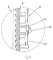
- the first spacer 4 is by one of the first supporting part 2 protruding tube profile rectangular cross section formed on two mutually parallel outer surfaces as Sliding connection means first teeth 6 having.
- the second spacer 5 is through a protruding from the second support part 3 Profile piece with a U-shaped cross section formed, which lies on the inside Legs as a second sliding connecting means Teeth 7 has.
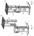
- the serrations 6, 7 are shaped so that they have no undercut and by im Cross section of approximately rectangular rod shapes are formed. In the assembly target position, the for example, shown in Figure 2 the serrations 6, 7 into one another almost without play, so that movements in the longitudinal direction of the Spacers 4, 5 are prevented.
- the toothless side surfaces of the Pipe profile and the base surface of the U-shaped Profile pieces each have large areas Wall recesses 8, 9 so that when Concreting process also in the concrete mass the spacer 4 enclosed cavity can flow in.
- Each latch 10 is approximately at the free end L-shaped, on a toothless wall of the Pipe profile of the spacer 4 outside molded web formed. Not everyone resilient retaining lug 12 is also on an L-shaped, on a toothless wall of the spacer 4 molded on the outside. Here the web is stiff trained, whereas the web at the Lugs 10 is resilient.
- Each support part 2 or 3 consists of a Essential flat plate, which at its the each other side facing away from the supporting part Has push button-like connector 13.
- each on the corresponding support part 2 or 3 attachable installation part 1 has one parallel to the surface of the supporting part 2 or 3 Corresponding locking holes so that the installation part 1 with the respective Support part 2 or 3 plug-in and in Plug connection snapped like a push button is held.
- the second also shows the stiffening Spacer 5, which as a U-shaped Profile piece is formed over the legs and the base outside Stiffening webs 15.
- the invention provides an arrangement for Available that are relatively easy to manufacture handle is with the impurities Do not bother handling when a noticeable Target mounting position is adjustable, which too is secured and extremely stable and is also torsionally stable.
- the invention is not based on that Embodiment limited, but in The scope of the disclosure is often variable.
Landscapes
- Engineering & Computer Science (AREA)
- Architecture (AREA)
- Civil Engineering (AREA)
- Structural Engineering (AREA)
- Forms Removed On Construction Sites Or Auxiliary Members Thereof (AREA)
- Mutual Connection Of Rods And Tubes (AREA)
Applications Claiming Priority (2)
| Application Number | Priority Date | Filing Date | Title |
|---|---|---|---|
| DE10161172 | 2001-12-13 | ||
| DE10161172A DE10161172B4 (de) | 2001-12-13 | 2001-12-13 | Anordnung aus Kunststoff für die Betonbauinstallation |
Publications (2)
| Publication Number | Publication Date |
|---|---|
| EP1322013A2 true EP1322013A2 (fr) | 2003-06-25 |
| EP1322013A3 EP1322013A3 (fr) | 2004-10-06 |
Family
ID=7709018
Family Applications (1)
| Application Number | Title | Priority Date | Filing Date |
|---|---|---|---|
| EP02022721A Withdrawn EP1322013A3 (fr) | 2001-12-13 | 2002-10-11 | Dispositif en plastique pour installation dans une construction en beton |
Country Status (2)
| Country | Link |
|---|---|
| EP (1) | EP1322013A3 (fr) |
| DE (1) | DE10161172B4 (fr) |
Cited By (1)
| Publication number | Priority date | Publication date | Assignee | Title |
|---|---|---|---|---|
| EP2525459A3 (fr) * | 2011-05-20 | 2013-12-25 | Agro Ag | Fixation pour support d'appareils |
Family Cites Families (1)
| Publication number | Priority date | Publication date | Assignee | Title |
|---|---|---|---|---|
| FR2763755B1 (fr) * | 1997-05-22 | 1999-08-06 | Capri Codec Sa | Ensemble reglable en plastique de maintien d'elements tels que des boitiers d'appareillage electrique entre des banches |
-
2001
- 2001-12-13 DE DE10161172A patent/DE10161172B4/de not_active Expired - Lifetime
-
2002
- 2002-10-11 EP EP02022721A patent/EP1322013A3/fr not_active Withdrawn
Cited By (1)
| Publication number | Priority date | Publication date | Assignee | Title |
|---|---|---|---|---|
| EP2525459A3 (fr) * | 2011-05-20 | 2013-12-25 | Agro Ag | Fixation pour support d'appareils |
Also Published As
| Publication number | Publication date |
|---|---|
| DE10161172B4 (de) | 2004-07-29 |
| DE10161172A1 (de) | 2003-07-03 |
| EP1322013A3 (fr) | 2004-10-06 |
Similar Documents
| Publication | Publication Date | Title |
|---|---|---|
| DE2941008C2 (de) | Gestell | |
| EP0298225B1 (fr) | Tour à niveaux pour présentation de marchandises | |
| DE3533134C2 (de) | Kupplungsstück | |
| DE102005035702A1 (de) | Platten- und Trägersystem für Konstruktionsspielzeuge | |
| DE2324697A1 (de) | Zerlegbarer gegenstand, insbesondere moebelstueck, und einzelbauteil zum aufbau des gegenstandes | |
| DE2926976C2 (de) | Aus einzelnen Elementen zusammensetzbarer Körper | |
| DE4421398C2 (de) | Beschlag zum Verbinden von Bauteilen | |
| EP3421691B1 (fr) | Cylindre de fermeture modulaire | |
| DE202010010620U1 (de) | Bodenabdeckung | |
| DE102014218466B4 (de) | Steckrahmensystem | |
| EP1122359A2 (fr) | Tamis et son procédé de fabrication | |
| EP1322013A2 (fr) | Dispositif en plastique pour installation dans une construction en beton | |
| EP0018658A2 (fr) | Structure linéaira,bidimensionnelle ou tridimensionnelle déformable et assemblage de pivotement pour une telle structure | |
| DE2300532C2 (de) | Wärmeisolierendes Verbundprofil für Fensterrahmen, Türrahmen od.dgl | |
| DE102016004917A1 (de) | Beschlag für ein Fenster, eine Tür oder dergleichen | |
| DE20120166U1 (de) | Anordnung aus Kunststoff für die Betonbauinstallation | |
| EP0307628B2 (fr) | Structure réticulée avec barres et noeuds | |
| DE2435359B2 (de) | Lösbare, auf unterschiedliche Türdicken einstellbare Dornbefestigung von Türhandhaben | |
| DE2721541C3 (de) | Rasterdecke | |
| EP1580341B1 (fr) | Élément de liaison pour une construction de profilés et construction de profilés | |
| DE10140878B4 (de) | Verbindungseinrichtung für eine Holz-Pfosten-Riegel-Verbindung | |
| DE4136509A1 (de) | Gliedermassstab, insbesondere aus kunststoff | |
| DE3729664A1 (de) | Aus profilschienen und diese verbindenden riegelelementen bestehender rahmenaufbau, insbesondere zum aufbau eines messestandes | |
| EP0007006A1 (fr) | Caillebotis pour le revêtement d'un plancher ou pour former un gratte-pied | |
| EP2537570A2 (fr) | Filtre à manches |
Legal Events
| Date | Code | Title | Description |
|---|---|---|---|
| PUAI | Public reference made under article 153(3) epc to a published international application that has entered the european phase |
Free format text: ORIGINAL CODE: 0009012 |
|
| AK | Designated contracting states |
Designated state(s): AT BE BG CH CY CZ DE DK EE ES FI FR GB GR IE IT LI LU MC NL PT SE SK TR |
|
| AX | Request for extension of the european patent |
Extension state: AL LT LV MK RO SI |
|
| PUAL | Search report despatched |
Free format text: ORIGINAL CODE: 0009013 |
|
| AK | Designated contracting states |
Kind code of ref document: A3 Designated state(s): AT BE BG CH CY CZ DE DK EE ES FI FR GB GR IE IT LI LU MC NL PT SE SK TR |
|
| AX | Request for extension of the european patent |
Extension state: AL LT LV MK RO SI |
|
| 17P | Request for examination filed |
Effective date: 20041022 |
|
| AKX | Designation fees paid |
Designated state(s): AT BE BG CH CY CZ DE DK EE ES FI FR GB GR IE IT LI LU MC NL PT SE SK TR |
|
| GRAP | Despatch of communication of intention to grant a patent |
Free format text: ORIGINAL CODE: EPIDOSNIGR1 |
|
| STAA | Information on the status of an ep patent application or granted ep patent |
Free format text: STATUS: THE APPLICATION IS DEEMED TO BE WITHDRAWN |
|
| 18D | Application deemed to be withdrawn |
Effective date: 20070411 |