EP1322031A2 - Anlaufverfahren für eine bürstenlose elektrische Rotationsmaschine zum Antrieb eines Verbrennungsmotors - Google Patents
Anlaufverfahren für eine bürstenlose elektrische Rotationsmaschine zum Antrieb eines Verbrennungsmotors Download PDFInfo
- Publication number
- EP1322031A2 EP1322031A2 EP02025013A EP02025013A EP1322031A2 EP 1322031 A2 EP1322031 A2 EP 1322031A2 EP 02025013 A EP02025013 A EP 02025013A EP 02025013 A EP02025013 A EP 02025013A EP 1322031 A2 EP1322031 A2 EP 1322031A2
- Authority
- EP
- European Patent Office
- Prior art keywords
- energization
- phase
- internal combustion
- combustion engine
- rotor
- Prior art date
- Legal status (The legal status is an assumption and is not a legal conclusion. Google has not performed a legal analysis and makes no representation as to the accuracy of the status listed.)
- Granted
Links
- 238000000034 method Methods 0.000 title claims abstract description 37
- 238000002485 combustion reaction Methods 0.000 title claims abstract description 27
- 230000005415 magnetization Effects 0.000 claims abstract description 39
- 238000004804 winding Methods 0.000 claims abstract description 34
- 230000003247 decreasing effect Effects 0.000 claims description 7
- 230000000670 limiting effect Effects 0.000 claims description 3
- 239000007858 starting material Substances 0.000 description 6
- XEEYBQQBJWHFJM-UHFFFAOYSA-N Iron Chemical group [Fe] XEEYBQQBJWHFJM-UHFFFAOYSA-N 0.000 description 4
- 238000001816 cooling Methods 0.000 description 4
- 238000010586 diagram Methods 0.000 description 4
- 230000002441 reversible effect Effects 0.000 description 4
- 238000009499 grossing Methods 0.000 description 3
- 230000006835 compression Effects 0.000 description 2
- 238000007906 compression Methods 0.000 description 2
- 230000004048 modification Effects 0.000 description 2
- 238000012986 modification Methods 0.000 description 2
- 230000002829 reductive effect Effects 0.000 description 2
- 239000003990 capacitor Substances 0.000 description 1
- 230000000694 effects Effects 0.000 description 1
- 230000002401 inhibitory effect Effects 0.000 description 1
- 230000003993 interaction Effects 0.000 description 1
- 230000005389 magnetism Effects 0.000 description 1
- 230000005405 multipole Effects 0.000 description 1
- 229910001172 neodymium magnet Inorganic materials 0.000 description 1
- 239000004065 semiconductor Substances 0.000 description 1
- 238000004513 sizing Methods 0.000 description 1
Images





Classifications
-
- H—ELECTRICITY
- H02—GENERATION; CONVERSION OR DISTRIBUTION OF ELECTRIC POWER
- H02P—CONTROL OR REGULATION OF ELECTRIC MOTORS, ELECTRIC GENERATORS OR DYNAMO-ELECTRIC CONVERTERS; CONTROLLING TRANSFORMERS, REACTORS OR CHOKE COILS
- H02P6/00—Arrangements for controlling synchronous motors or other dynamo-electric motors using electronic commutation dependent on the rotor position; Electronic commutators therefor
- H02P6/20—Arrangements for starting
-
- H—ELECTRICITY
- H02—GENERATION; CONVERSION OR DISTRIBUTION OF ELECTRIC POWER
- H02P—CONTROL OR REGULATION OF ELECTRIC MOTORS, ELECTRIC GENERATORS OR DYNAMO-ELECTRIC CONVERTERS; CONTROLLING TRANSFORMERS, REACTORS OR CHOKE COILS
- H02P2209/00—Indexing scheme relating to controlling arrangements characterised by the waveform of the supplied voltage or current
- H02P2209/09—PWM with fixed limited number of pulses per period
-
- Y—GENERAL TAGGING OF NEW TECHNOLOGICAL DEVELOPMENTS; GENERAL TAGGING OF CROSS-SECTIONAL TECHNOLOGIES SPANNING OVER SEVERAL SECTIONS OF THE IPC; TECHNICAL SUBJECTS COVERED BY FORMER USPC CROSS-REFERENCE ART COLLECTIONS [XRACs] AND DIGESTS
- Y10—TECHNICAL SUBJECTS COVERED BY FORMER USPC
- Y10S—TECHNICAL SUBJECTS COVERED BY FORMER USPC CROSS-REFERENCE ART COLLECTIONS [XRACs] AND DIGESTS
- Y10S388/00—Electricity: motor control systems
- Y10S388/907—Specific control circuit element or device
- Y10S388/912—Pulse or frequency counter
Definitions
- the present invention relates to a method of starting an electric brushless rotating machine and particularly to a method of starting an electric brushless rotating machine appropriated for generating a large torque at the startup stage.
- Abrushless motor is provided as an electric rotating machine where the energization of three-phase stator windings for driving a rotating member (referred to as a rotor hereinafter) is switched from one to another whenever the rotor rotates through 120 degrees of the electric angle.
- a conventional brushless motor has commonly a position detector element such as a Hall device for detecting the rotating position of the rotor.
- a position detector element such as a Hall device for detecting the rotating position of the rotor.
- Another type of brushless motor which includes no position detector element has been developed in response to the demand for down-sizing of the brushless motor.
- a brushless motor is disclosed in Japanese Patent Publication (Heisei)5-24760 where, in view of any two different phases of the three-phase stator windings being energized in a sequence, the voltage induced at the remaining not-energized phase is measured and used for calculating the rotating position of the rotor.
- the forced commutation means that any two desired phases of the stator, e.g. U and V, are energized regardless of the position of the rotor (which is hence referred to as one-phase energization hereinafter) .
- the position of the rotor is detected from the induced voltage and then a common procedure of the energization will follow in relation to the detected rotor position.
- the positional relationship between the rotor and the stator when they stop their movement as the motor has been deenergized is determined by attracting and repulsing forces of the magnets .
- the motor is an outer rotor type brushless motor having three-phase stator windings
- its positional relationship between the rotor and the stator is expressed by six different pausing modes, p1 to p6, shown in Fig. 13.
- Fig. 13 illustrates an arrangement of a primary part of the brushless motor in addition to the six pausing modes of the position relationship between the rotor and the stator of which the movement stops as the motor has been deenergized.
- the counter clockwise direction is the forward direction Rs of the rotor while the clockwise direction is the reverse direction Rr.
- the stator 100 and the rotor 200 of the brushless motor are disposed inward and outward respectively.
- the stator 100 has magnetic poles 300 of U, V, and W phase.
- the magnetic poles 300 incorporate windings.
- the rotor 200 has a row of permanent magnets m1, m2, m3, ... of which the polarity alternates between N and S along the circumference .
- the magnet m2 at S is attracted by the U phase at N but repulsed by the W phase at S. This causes the rotor 200 to rotate at a maximum torque in the forward direction Rs.
- the U phase at N attracts the magnet m2 at S but repulses the magnet m3 at N hence allowing the rotor 200 to rotate at the maximum torque in the forward direction Rs.
- the attraction between the U phase at N and the magnet m2 at S is balanced with the attraction between the W phase at S and the magnet m1 at N. This permits no movement of the rotor 200.
- the magnet m2 at N is attracted by the W phase at S while the magnet m1 at S is repulsed by the same. This causes the rotor 200 to rotate in the reverse direction Rr.
- the U phase at N attracts the magnet m3 at S but repulses the magnet m2 at N hence allowing the rotor 200 to rotate further in the reverse direction Rr.
- the repulsion between the U phase at N and the magnet m2 at N is balanced with the repulsion between the W phase at S and the magnet m1 at S. This permits no movement of the rotor 200.
- the startup torque may be generated non or too small at the initial pausing modes p3 and p6 thus disallowing the brushless motor to start up.
- this disadvantage will be significant.
- the motor for starting an internal combustion engine even if its output is great, may fail to generate a desired level of the startup torque because the friction in the engine is too high.
- the rotor rotates in the reverse direction and fails to generate a desired magnitude of the induced voltage needed for detecting the position of the rotor, hence inhibiting any normal energizing action. More particularly, by force commutation, the motor when remains free in the movement can be rotated in the forward direction two times out of six trials or at 1/3 of the probability.
- a first feature of the present invention is that a method of starting an electric brushless rotating machine for driving an internal combustion engine which has a magnetic rotor joined to an output shaft of the internal combustion engine and a set of stator windings of a first phase, a second phase, and a third phase arranged at equal phase intervals of an electric angle of 120 degrees so that the stator windings are energized in a sequence for forced commutation according to a rotating position detecting signal from the rotor, comprising the steps of, energizing between any two of the first, second, and third phase stator windings for initial magnetization at the startup to hold the magnetic rotor at a position, carrying out the forced commutation to energize the windings of the phases in a sequence while gradually increasing the level of the energization for forcefully rotating the magnet rotor, and generating the rotating position detecting signal from a voltage signal induced on the not-energized windings during the forced commutation and carrying out a normal action of the
- the internal combustion engine can be started up by a large level of the startup torque with no help of position detecting elements.
- the electric brushless rotating machine can hence be used as a brushless starter motor.
- a second feature of the present invention is that the timing for switching from the forced commutation to the normal energization is taken when the number of revolutions or the full turning motion determined from the rotating position detecting signal reaches its predetermined level or times.
- a third feature of the present invention is that the duty of PWM during the energization after the completion of the initial magnetization is gradually increased with a limiter arranged for limiting the energizing current to a specific level.
- the startup to a desired number of revolutions can smoothly be conducted while the capacity of a driver for energization remains minimized.
- a fourth feature of the present invention allows the energizing current to be gradually increased in the amount for the initial magnetization while being monitored not to exceed a predetermined level and when reaching the level, to be held at its level for continuous energization.
- the upper limit level of the current can continuously be supplied during the forced commutation.
- the method of starting an electric brushless rotating machine can produce a greater startup torque.
- the climb over torque is required for starting an internal combustion engine of a large startup torque type, it can simply be provided with no use of position sensors.
- a fifth feature of the invention is that the rotating position detecting signal is determined from a voltage signal induced on the windings of the magnetic rotor not energized by the forced commutation and when the number of revolutions or the fully rotating motion reaches its predetermined level or times, the rotating position detecting signal is used for controlling the energization to the winding of each phase.
- the operation can automatically be switched to a normal action by the switching based on the number of revolutions.
- a sixth feature of the invention is that the energization is canceled when the energizing current exceeds the predetermined level.
- the initial magnetization can be prevented from overload operations.
- a seventh feature of the present invention allows the energization to each phase winding to be controlled through quantitatively increasing or decreasing the duty of PWM.
- the energization to each phase winding can be controlled by a simple means.
- Fig. 1 is a side view of an electric brushless rotating machine of the embodiment in the form of an engine generator system.
- Fig. 2 is a cross sectional view taken along the line V-V of Fig. 1.
- the engine generator system 1 includes an engine 2 and a generator 3.
- the generator 3 is a magnet type multi-pole power generator.
- the engine 2 has a crank shaft 4 thereof supported by a bearing 6 installed in a side wall 5a of a crank case 5 to extend at one end outwardly of the engine 2.
- a star-shaped annular iron core 7 is fixedly mounted by bolts 8 to a boss region about the crank shaft 4 of the side wall 5a of the crank case 5.
- the iron core 7 comprises an annular center yoke portion 7a with twenty seven projections 7b extending radially from the center yoke portion.
- the projections 7b have three-phase alternate windings provided thereon thus constituting a stator 8.
- the iron core 7 is multi-poled for generating a large output of power and its center yoke portion 7a and projection 7b are decreased in the radial length thus contributing to the lower weight of the system.
- the crank shaft 4 has a hub 9 of a forged member fitted onto the distal end thereof.
- the hub 9 is linked to a flywheel 10 which also acts as a rotor yoke.
- the flywheel 10 is a pressed member of a cup-like shape comprising a disk portion 10a and a cylinder portion 10b.
- the disk portion 10a is fixedly joined to the hub 9 so that the cylinder portion 10b encloses the outsides of the projections 7b of the iron core 7.
- neodymium magnets 11 having higher magnetism are circumferentially mounted on the inner side of the cylinder portion 10b of the flywheel 10 thus constituting a magnetic rotor 12 of an outer rotor type .
- the rotor 12 has the magnets 11 aligned tightly on the inner side of the cylinder portion 10b to have a sufficient mass and can hence function successfully as the flywheel.
- a cooling fan 13 is mounted to the disk portion 10a of the flywheel 10.
- the cooling fan 13 has a set of blades 13b provided upright and arranged circumferentially on one side of an annular base 13a thereof.
- the annular base 13a is fixedly mounted to the outer side of the disk portion 10a of the flywheel 10.
- the cooling fan 13 is enclosed in a fan cover 14 which provides a cooling air passage 14a extending from the outer side of the flywheel 10 to the engine 2.
- Fig. 3 is a schematic view of the engine generator system 1.
- the generator 3 is driven by the (internal combustion) engine 2 to generate a three-phase alternating current.
- the alternating current output of the generator 3 is full-wave rectified to a direct current by a converter 15 which comprises a rectifying circuit having a group of semiconductor rectifier devices connected in a bridge form.
- the direct current output of the converter 15 is then smoothed by a capacitor smoothing circuit 16 and transferred to an inverter 17 where it is converted into an alternating current at a desired frequency by the FET bridge circuit of the inverter 17.
- the alternating current output of the inverter 17 is received by a demodulation filter 18 where a lower frequency component (e.g. commercial frequencies) is passed through.
- the alternating current passed through the demodulation filter 18 is transferred via a relay 19 and a fuse 20 to an output terminal 21.
- the relay 19 remains open at the startup of the engine 2 and is then closed when the engine 2 runs to a specific level.
- the generator 3 in the engine generator system 1 is also used as a starter for starting the engine 2.
- the generator 3 includes a starter driver 22.
- a rectifying circuit 23 and a smoothing circuit 24 are provided for supplying the starter driver 22 with a current for starting the engine 2.
- the rectifying circuit 23 comprises a harmonic filter 231 and a converter 232.
- the harmonic filter 231 has a fuse 20A and is connected by the fuse 20A to the output terminal 21.
- the output of the generator 3 is connected to, for example, a single-phase power source 25 at 200 VAC and receives the alternating current from the source 25 for the startup action.
- the alternating current is transmitted to the harmonic filter 231 where its harmonic is removed off, converted to a direct current by the converter 232, and received as a power supply via the smoothing circuit 24 by the starter driver 22.
- the starter driver 22 supplies the three-phase windings of the generator 3 in a predetermined sequence with the current for starting the engine 2.
- a switching device (FET) 221, a CPU 222, and a sensorless driver 223 employing no sensor (magnetic pole detector) for detecting the location of the rotor 12.
- the sensorless driver 223 measures the location of the rotor from voltage signals induced on the first, second, and third stator windings arranged at equal intervals of a 120-degree phase difference and determines the energization of the stator windings.
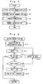
- Fig. 4 is a flowchart for controlling the startup of the engine generator system 1.
- the generator 3 When the generator 3 starts operating after its free pausing state, it may fail to have a desired startup torque during the forced commutation due to the negative positional relationship between the rotor and the stator. Also, the forward rotation may be interrupted.
- Steps S1 and S2 conduct the first and the second action of the initial magnetization for shifting the rotor 12 to its desired location relative to the stator so that the desired startup torque is gained by the forced commutation and the forward rotation is encouraged. The initial magnetization then allows the rotor 12 to move to the desired location for gaining its maximum torque .
- the first and the second action of the initial magnetization are different in the energizing phase but equal in the procedure (as will be described later in more detail) . Even when the rotor and the stator remain at their free pausing state or at any positional relationship (ranging from p1 to p6 in Fig. 13), the two initial magnetizing actions can shift the rotor 12 to a desired position for producing the maximum torque. If the duration of the initial magnetization is too short, the rotor may rotate without steadiness and jog at its stop position. The energizing period for the initial magnetization will hence extend until the rotor is located with stability, i.e. substantially one second.
- the forced commutation involves single-phase energization from the positional relationship between the rotor and the stator when the maximum torque is gained after the second action of the initial magnetization.
- the induced voltage from the non-energized phase is measured through the forced commutation and then used for detecting the position of the rotor 12. As the position of the rotor 12 has been determined from the induced voltage detected, the procedure goes to Step S4 where a normal procedure of the energization is carried out.
- Fig. 5 is a flowchart for the initial magnetization (of both the first and the second action).
- the FET 221 is driven for energization of a predetermined phase.
- the first action of the initial magnetization energizes from the V phase to the U phase while the second action of the initial magnetization energizes from the V phase to the W phase.
- Step S11 follows where the initial value of energization duty is increased by a predetermined rate (for example, 1 %). It is then examined at Step S12 whether or not the rotor 12 stops at any initial location (ranging from p1' to p6') in relation to the stator after a counter electromotive force is produced. When the rotor 12 remains not moved, the counter electromotive force is zero.
- the pausing of the rotor 12 at the initial location can be determined when the counter electromotive force is zero.
- the counter electromotive force Once the counter electromotive force has been released, its value is examined whether zero or not. If no counter electromotive force has been released, it is judged "no" at the step.
- "yes" at Step S12 it is judged that the initial magnetization has been completed and the procedure goes to the next step. More specifically, when the first action of the initial magnetization is completed, the procedure goes to the second action of the initial magnetization. When the second action of the initial magnetization is completed, the procedure goes to the force commutation.
- Step S12 When it is judged "no" at Step S12, the procedure advances to Step S13 where it is examined whether the energization duty of the FET 221 exceeds an upper limit (e.g. 50 %) or not. If not, the energization is carried out at the current duty (at Step S14) and the procedure returns to Step S11.
- an upper limit e.g. 50 % or not. If not, the energization is carried out at the current duty (at Step S14) and the procedure returns to Step S11.
- the rotor 12 fails to pause at the initial location with the duty reaching the upper limit or the counter electromotive force has not yet been released, it is judged "yes” at Step S13. This indicates a lockup state or an overloaded state and the duty is turned back to zero at Step S15 before the procedure is terminated with fail (at Step S16).
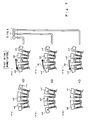
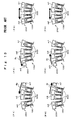
- the first and the second action of the initial magnetization will be explained in more detail referring to Figs. 6 and 7.
- the initial pausing modes from p1 to p6 illustrated at the left end in Figs. 6 and 7 indicate the initial location of the rotor 200 relative to the stator 100 when the generator stops spontaneously as are identical to those p1 to p6 shown in Fig. 13.
- the polarity of the V phase is turned to N and the polarity of the U phase is turned to S.
- the polarity of the V phase is turned to N and the polarity of the W phase is turned to S.
- the rotor 200 pauses with the permanent magnet m2 at S and the permanent magnet m1 at N held by the N pole of the V phase and the S pole of the W phase respectively. It is hence apparent that the pausing mode p1'' is established when the second action of the initial magnetization is carried out at any pausing mode of p1' to p6' determined by the first action of the initial magnetization.
- all the different pausing modes p1 to p6 can be converged to the single pausing mode p1'' through the first and the second action of the initial magnetization.
- the positional relationship between the stator and the rotor involves the generation of amaximumof the startup torque in the revolution in the forward direction when the U and W phases are shifted to the N and S poles respectively by the succeeding forced commutation from the U phase to the W phase.
- the generator at the initial pausing mode p1'' is driven by the forced commutation, it starts up with its rotor and stator generating the maximum torque and can thus rotate without difficulty in the forward direction.
- Fig. 11 illustrates the duration required before the rotation of the rotor becomes stable when the stator and the rotor at any of the initial pausing modes p1 to p6 have been single-phase magnetized. If the duration of the initial magnetization is too short, the rotor may rotate unstable and create a rocking motion at its pausing location. As apparent from Fig. 11, the duration from the startup of the initial magnetization and to the rotor becoming stable is a maximum or substantially 0.7 second at the initial pausing mode p5. It is hence desired that the duration for the initial magnetization before the rotation of the rotor becomes stable is substantially one second in consideration of a generous margin.
- Fig. 8 is a flowchart showing a procedure of the forced commutation.
- Step S20 the energization to a predetermined phase, e.g. from the U phase to the W phase, is conducted.
- Step S21 follows where the duty of PWM is gradually increased, for example, at steps of 1 %. It is examined at Step S22 whether or not the current required for generating a torque of starting the engine or getting over the upper dead point for the compression exceeds an upper limit determined from the allowance for the energization (over-current).
- Step S22 When it is judged "yes” at Step S22 or the current exceeds the upper limit, the procedure jumps to Step S24 where the duty is reduced, for example, by 1 % to protect a relevant component or switching device in the driver.
- Step S25 the forced commutation is executed/continued at the 1% reduced duty.
- Step S22 When it is judged "no" at Step S22, the procedure moves to Step S23 for examining again whether or not the internal combustion engine has completed its full turning motion of predetermined times, for example, 10 times. When so, it is judged at Step S23 that the number of revolutions by the forced commutation is turned stable and the procedure for the force commutation is terminated before returning back to the normal energization procedure shown in Fig. 10. It is also possible to judge the rotating action from the number of revolutions per unit time instead of the foregoing predetermined number.
- the sensorless driver 223 generates a rotating position detecting signal from the voltage induced on the not-energized windings and drives the rotor according to the rotating position detecting signal. Also, the number of revolutions or the full turning motion of predetermined times in the internal combustion engine may be measured from the rotating position detecting signal.
- the energization to any of the windings can be efficient without a redundancy of the energizing current. Also, when the duty reaches its upper limit, it can be decreased to inhibit over-current in the energization to the windings thus permitting the continuous operation.
- Fig. 9 is a flowchart showing a modification of the forced commutation. It may be necessary in respect of the capability of the switching element or the driver in the engine generator system 1 to carry out some times the forced commutation with over-currents exceeding the upper limit and overcome or climb over the upper dead point for the compression using a climb over torque. This is implemented by the modification of the forced commutation. Like steps are denoted by like numerals as those shown in Fig. 8 and will be explained in no more detail.
- Step S22 When it is judged at Step S22 that over-current is drawn, the procedure goes to Step S31 for increasing the count by one. It is then examined at Step S32 whether or not the count is greater than e.g. 10. When not, the procedure moves to Step S25 for carrying out the forced commutation at the duty of over-current. The forced commutation with over-current is continued until the count reaches 10. When the over-current remains (as judged "not” at Step S32), the duty is decreased by 1 % at Step S33 to eliminate the over-current.
- Fig. 10 is a flowchart for the normal energization.
- the duty is increased by 1 %. It is then examined at Step S42 whether or not the duty reaches its upper limit or the over-current is drawn. When not, the procedure goes to Step S43 where it is examined whether or not the number of revolution is higher than a predetermined level (for example, 800 rpm).
- a predetermined level for example, 800 rpm.
- the procedure goes to Step S44 for turning the duty to 0 %.
- Step S45 for decreasing the duty by 1 % to eliminate the over-current. Step S46 follows where the action is executed at the decreased duty.
- Fig. 12 is a graphic diagram showing changes in the energizing current, the PWM duty, and the number of revolutions of the crank shaft in the engine when the action of energization shifts from the forced commutation after the completion of the initial magnetization to the normal energization. It is apparent from the diagram that the number of revolutions in the engine is smoothly increased to a desired level from the forced commutation after the startup of the engine to the normal commutation.
- the present invention defined in claims 1 to 3 allows the startup of an internal combustion engine of a large startup torque type to be carried out the action of an electric brushless rotating machine equipped with non of position detector devices such as Hall devices. It is also simply permitted that the electric brushless rotating machine serves as a brushless stator motor.
- the number of revolutions or the full turning motion of predetermined times in the internal combustion engine is measured from the rotating position detecting signal produced on the basis of a voltage signal induced on the not-energized windings and when the number reaches its predetermined level, the operation is automatically switched to a normal mode. This allows the forced commutation to be switched to a normal action of energization easily and smoothly.
- the duty of PWM during the energization after the completion of the initial magnetization is gradually increased with a limiter provided for limiting the energizing current to a specific level.
- the upper limit level of the current is continuously supplied during the forced commutation when a climb over torque is required for starting the internal combustion engine.
- the operation when the number of revolutions or the full turning motion measured from the rotating position detecting signal reaches its predetermined level or times, i.e. the relationship between the commutation and the rotation becomes at a degree of stability, the operation can automatically be switched to a normal operation based on the number of revolutions. As a result, the switching to the normal operation can be carried out easily and smoothly.
- the initial magnetization can be prevented from over-loading.
- the energization to each phase winding can be controlled by a simple means thus improving the operational reliability.
Landscapes
- Engineering & Computer Science (AREA)
- Power Engineering (AREA)
- Control Of Motors That Do Not Use Commutators (AREA)
Applications Claiming Priority (4)
| Application Number | Priority Date | Filing Date | Title |
|---|---|---|---|
| JP2001377151 | 2001-12-11 | ||
| JP2001377152A JP2003189675A (ja) | 2001-12-11 | 2001-12-11 | 内燃機関駆動用ブラシレス回転電機の始動方法 |
| JP2001377151A JP4046266B2 (ja) | 2001-12-11 | 2001-12-11 | 内燃機関駆動用ブラシレス回転電機の始動方法 |
| JP2001377152 | 2001-12-11 |
Publications (3)
| Publication Number | Publication Date |
|---|---|
| EP1322031A2 true EP1322031A2 (de) | 2003-06-25 |
| EP1322031A3 EP1322031A3 (de) | 2003-10-22 |
| EP1322031B1 EP1322031B1 (de) | 2017-08-30 |
Family
ID=26624987
Family Applications (1)
| Application Number | Title | Priority Date | Filing Date |
|---|---|---|---|
| EP02025013.0A Expired - Lifetime EP1322031B1 (de) | 2001-12-11 | 2002-11-08 | Anlaufverfahren für eine bürstenlose elektrische Rotationsmaschine zum Antrieb eines Verbrennungsmotors |
Country Status (5)
| Country | Link |
|---|---|
| US (1) | US6774590B2 (de) |
| EP (1) | EP1322031B1 (de) |
| KR (1) | KR100654415B1 (de) |
| CN (1) | CN1424816A (de) |
| TW (1) | TW575718B (de) |
Cited By (1)
| Publication number | Priority date | Publication date | Assignee | Title |
|---|---|---|---|---|
| CN107251406A (zh) * | 2015-03-09 | 2017-10-13 | 新电元工业株式会社 | 起动发电装置、以及起动发电方法 |
Families Citing this family (30)
| Publication number | Priority date | Publication date | Assignee | Title |
|---|---|---|---|---|
| EP2113999A3 (de) * | 2001-09-25 | 2010-01-06 | Daikin Industries, Ltd. | Phasenstromerkennungsvorrichtung |
| JP3948009B2 (ja) * | 2001-10-03 | 2007-07-25 | 株式会社安川電機 | 3相交流電動機の巻線切換装置 |
| US7514887B2 (en) * | 2003-10-24 | 2009-04-07 | A. O. Smith Corporation | Electrical machine and method of controlling the same |
| CA2899485A1 (en) * | 2003-10-24 | 2005-05-12 | Regal Beloit America, Inc. | Electrical machine and method of controlling the same |
| US7608964B2 (en) * | 2004-03-31 | 2009-10-27 | Daikin Industries, Ltd. | Motor, blower, compressor, and air conditioner |
| KR100597297B1 (ko) * | 2004-09-21 | 2006-07-05 | 엘지전자 주식회사 | 센서리스 비엘디씨 모터의 초기 구동 방법 |
| KR100597296B1 (ko) * | 2004-09-21 | 2006-07-05 | 엘지전자 주식회사 | 센서리스 비엘디씨 모터의 초기 구동 방법 |
| TWI277285B (en) * | 2005-03-02 | 2007-03-21 | Delta Electronics Inc | Starting method of a tapered-air gap motor |
| KR100774006B1 (ko) * | 2005-06-28 | 2007-11-08 | 삼성전자주식회사 | 3상 bldc 모터의 제어장치 및 3상 bldc모터의제어방법 |
| US7468595B2 (en) * | 2005-07-26 | 2008-12-23 | Eaton Corporation | System and method of controlling the start-up of an adjustable speed motor drive based sinusoidal output power conditioner |
| CN101713904B (zh) * | 2005-12-06 | 2012-08-29 | 松下电器产业株式会社 | 数字相机、相机机身、相机系统及该数字相机的控制方法 |
| US7710058B2 (en) * | 2007-12-13 | 2010-05-04 | Hamilton Sundstrand Corporation | Motor drive architecture for high frequency AC bus |
| DE102008037543A1 (de) | 2007-12-28 | 2009-07-02 | DENSO CORPORARTION, Kariya-shi | Motorsteuervorrichtung, Fahrzeuglüfter-Ansteuervorrichtung und Motorsteuerverfahren |
| US8242725B2 (en) * | 2008-04-15 | 2012-08-14 | Ford Global Technologies, Llc | Method for operating sensorless and brushless motors |
| US9385641B2 (en) * | 2009-11-18 | 2016-07-05 | Standard Microsystems Corporation | System and method for inducing rotation of a rotor in a sensorless motor |
| US8901867B2 (en) | 2011-04-28 | 2014-12-02 | Regal Beloit America, Inc. | Electrical machine, method of controlling an electrical machine, and system including an electrical machine |
| JPWO2012147197A1 (ja) * | 2011-04-28 | 2014-07-28 | 新電元工業株式会社 | ブラシレスモータ制御装置、およびブラシレスモータ制御方法 |
| JP5998434B2 (ja) * | 2011-06-23 | 2016-09-28 | 株式会社ジェイテクト | ブラシレスdcモータのセンサレス制御装置 |
| US9559623B2 (en) | 2013-08-30 | 2017-01-31 | Regal Beloit America, Inc. | Method of controlling an electrical machine |
| CN104064083B (zh) * | 2014-06-20 | 2016-08-24 | 三垦力达电气(江阴)有限公司 | 一种电网模拟控制系统 |
| JP6462503B2 (ja) | 2015-06-17 | 2019-01-30 | 株式会社ミツバ | エンジンスタータシステム |
| TWI595741B (zh) * | 2016-06-28 | 2017-08-11 | 建準電機工業股份有限公司 | 馬達、其啓動控制方法及具有該馬達的風扇 |
| DE102017217113A1 (de) * | 2017-09-26 | 2019-03-28 | Robert Bosch Gmbh | Verfahren zum Betreiben eines Verbrennungsmotors und elektronisches Steuergerät für einen Verbrennungsmotor |
| US10330070B2 (en) * | 2017-11-14 | 2019-06-25 | Gm Global Technology Operations Llc. | Method and apparatus for operating a starter for an internal combustion engine |
| JP2019097315A (ja) * | 2017-11-23 | 2019-06-20 | 株式会社デンソー | 制御装置 |
| US10815954B2 (en) * | 2018-05-01 | 2020-10-27 | GM Global Technology Operations LLC | Starter for an internal combustion engine |
| CN108768225B (zh) * | 2018-05-29 | 2020-12-29 | 广东威灵电机制造有限公司 | 转子的预定位拖动方法、系统以及同步电机控制系统 |
| KR102422531B1 (ko) | 2019-12-12 | 2022-07-19 | 주식회사 현대케피코 | 차량용 모터 제어 장치 및 방법 |
| CN113507244B (zh) * | 2021-06-08 | 2023-05-23 | 捷和电机制品(深圳)有限公司 | 一种电机的控制方法、装置及电子设备 |
| CN119628470B (zh) * | 2025-02-17 | 2025-05-13 | 成都航天凯特机电科技有限公司 | 一种永磁同步电机启动方法及系统 |
Citations (2)
| Publication number | Priority date | Publication date | Assignee | Title |
|---|---|---|---|---|
| US6160367A (en) | 1998-07-07 | 2000-12-12 | Matsushita Electric Industrial Co., Ltd. | Apparatus and method for driving motor |
| DE19953265A1 (de) | 1999-11-05 | 2001-05-23 | Grundfos As | Verfahren zum Anfahren eines Gleichstrommotors |
Family Cites Families (14)
| Publication number | Priority date | Publication date | Assignee | Title |
|---|---|---|---|---|
| US3902073A (en) * | 1974-02-07 | 1975-08-26 | Gen Electric | Starter generator electrical system utilizing phase controlled rectifiers to drive a dynamoelectric machine as a brushless dc motor in the starter mode and to provide frequency conversion for a constant frequency output in the generating mode |
| DE3113092A1 (de) * | 1981-04-01 | 1982-10-21 | Volkswagenwerk Ag, 3180 Wolfsburg | "schaltungsanordnung zur erzeugung eines drehfelds fuer eine als schwungradstarter fuer eine fahrzeug-brennkraftmaschine dienende drehstrom-synchronmaschine" |
| US4484114A (en) * | 1982-03-04 | 1984-11-20 | Rotron, Incorporated | Self-starting brushless DC motor |
| JPS58172994A (ja) | 1982-04-02 | 1983-10-11 | Sony Corp | ブラシレスモ−タ |
| US4455513A (en) * | 1982-07-26 | 1984-06-19 | Imec Corporation | Self-starting transducerless, brushless D.C. motor controller |
| JP2533472B2 (ja) * | 1984-06-13 | 1996-09-11 | 株式会社日立製作所 | ブラシレス直流モ−タの起動法 |
| KR940001917B1 (ko) | 1990-08-28 | 1994-03-11 | 가부시기가이샤 도시바 | 센서레스 스핀들 모터 제어 장치 |
| JP2598180B2 (ja) | 1991-07-17 | 1997-04-09 | 三菱電機株式会社 | エレベータの停電時救出運転装置 |
| US5572097A (en) | 1991-10-03 | 1996-11-05 | Sgs-Thomson Microelectronics, Inc. | Method and apparatus for starting polyphase dc motor |
| JPH09219990A (ja) | 1996-02-14 | 1997-08-19 | Matsushita Electric Ind Co Ltd | センサレスdcブラシレスモータの制御駆動装置 |
| US6034494A (en) | 1998-01-20 | 2000-03-07 | Denso Corporation | Control device for brushless DC motor |
| JP2000156962A (ja) | 1998-11-19 | 2000-06-06 | Sawafuji Electric Co Ltd | アウタロータ型多極回転電機 |
| JP2000316298A (ja) | 1999-04-27 | 2000-11-14 | Mitsuba Corp | 始動発電機 |
| US6566830B2 (en) * | 2001-08-17 | 2003-05-20 | Delphi Technologies, Inc. | Method and system for controlling a permanent magnet machine |
-
2002
- 2002-10-25 TW TW91124907A patent/TW575718B/zh not_active IP Right Cessation
- 2002-10-29 US US10/282,053 patent/US6774590B2/en not_active Expired - Lifetime
- 2002-11-08 EP EP02025013.0A patent/EP1322031B1/de not_active Expired - Lifetime
- 2002-12-10 KR KR1020020078277A patent/KR100654415B1/ko not_active Expired - Fee Related
- 2002-12-10 CN CN02154582A patent/CN1424816A/zh active Pending
Patent Citations (2)
| Publication number | Priority date | Publication date | Assignee | Title |
|---|---|---|---|---|
| US6160367A (en) | 1998-07-07 | 2000-12-12 | Matsushita Electric Industrial Co., Ltd. | Apparatus and method for driving motor |
| DE19953265A1 (de) | 1999-11-05 | 2001-05-23 | Grundfos As | Verfahren zum Anfahren eines Gleichstrommotors |
Cited By (2)
| Publication number | Priority date | Publication date | Assignee | Title |
|---|---|---|---|---|
| CN107251406A (zh) * | 2015-03-09 | 2017-10-13 | 新电元工业株式会社 | 起动发电装置、以及起动发电方法 |
| CN107251406B (zh) * | 2015-03-09 | 2019-05-03 | 新电元工业株式会社 | 起动发电装置、以及起动发电方法 |
Also Published As
| Publication number | Publication date |
|---|---|
| EP1322031A3 (de) | 2003-10-22 |
| EP1322031B1 (de) | 2017-08-30 |
| KR20030047853A (ko) | 2003-06-18 |
| TW575718B (en) | 2004-02-11 |
| US20030107348A1 (en) | 2003-06-12 |
| CN1424816A (zh) | 2003-06-18 |
| KR100654415B1 (ko) | 2006-12-05 |
| US6774590B2 (en) | 2004-08-10 |
Similar Documents
| Publication | Publication Date | Title |
|---|---|---|
| EP1322031B1 (de) | Anlaufverfahren für eine bürstenlose elektrische Rotationsmaschine zum Antrieb eines Verbrennungsmotors | |
| JP4001331B2 (ja) | エンジン始動装置 | |
| EP1320183B1 (de) | Verfahren zum Starten einer bürstenlosen elektrischen Drehmaschine zum Antreiben eines Verbrennungsmotors | |
| US6787931B2 (en) | Starter generator for internal combustion engine | |
| JP4004872B2 (ja) | エンジン始動装置 | |
| US7362002B2 (en) | Automotive starter generator apparatus | |
| JP5109917B2 (ja) | 回転電機 | |
| JP2003189675A (ja) | 内燃機関駆動用ブラシレス回転電機の始動方法 | |
| JP4046266B2 (ja) | 内燃機関駆動用ブラシレス回転電機の始動方法 | |
| JP2010012937A (ja) | 動力伝達装置 | |
| JP2004028007A (ja) | エンジン始動装置 | |
| JP2000316298A (ja) | 始動発電機 | |
| CA2543413C (en) | Electrical machine and method of controlling the same | |
| JP2002186293A (ja) | 内燃機関用回転電機の制御装置 | |
| JP3283377B2 (ja) | 直流電動機の同期起動装置 | |
| JP3979637B2 (ja) | エンジン始動装置 | |
| JP2001069797A (ja) | 始動発電機の電流調整装置 | |
| JP2020156166A (ja) | スイッチトリラクタンスモータ制御装置及びスイッチトリラクタンスモータ制御方法 | |
| JP2002165485A (ja) | 内燃機関用スタータジェネレータ | |
| JPH09135599A (ja) | 発電機 | |
| JPS63181642A (ja) | エンジンの始動及び充電装置 |
Legal Events
| Date | Code | Title | Description |
|---|---|---|---|
| PUAI | Public reference made under article 153(3) epc to a published international application that has entered the european phase |
Free format text: ORIGINAL CODE: 0009012 |
|
| AK | Designated contracting states |
Designated state(s): AT BE BG CH CY CZ DE DK EE ES FI FR GB GR IE IT LI LU MC NL PT SE SK TR |
|
| AX | Request for extension of the european patent |
Extension state: AL LT LV MK RO SI |
|
| PUAL | Search report despatched |
Free format text: ORIGINAL CODE: 0009013 |
|
| AK | Designated contracting states |
Kind code of ref document: A3 Designated state(s): AT BE BG CH CY CZ DE DK EE ES FI FR GB GR IE IT LI LU MC NL PT SE SK TR |
|
| AX | Request for extension of the european patent |
Extension state: AL LT LV MK RO SI |
|
| 17P | Request for examination filed |
Effective date: 20031126 |
|
| AKX | Designation fees paid |
Designated state(s): DE FR GB IT |
|
| 17Q | First examination report despatched |
Effective date: 20100817 |
|
| GRAP | Despatch of communication of intention to grant a patent |
Free format text: ORIGINAL CODE: EPIDOSNIGR1 |
|
| STAA | Information on the status of an ep patent application or granted ep patent |
Free format text: STATUS: GRANT OF PATENT IS INTENDED |
|
| INTG | Intention to grant announced |
Effective date: 20170515 |
|
| RAP1 | Party data changed (applicant data changed or rights of an application transferred) |
Owner name: HONDA GIKEN KOGYO KABUSHIKI KAISHA |
|
| RIN1 | Information on inventor provided before grant (corrected) |
Inventor name: IIJIMA, YOSHIHIRO Inventor name: WAKITANI, TSUTOMU Inventor name: NAKAMURA, MITSURU Inventor name: INAGAWA, TOSHINORI |
|
| GRAS | Grant fee paid |
Free format text: ORIGINAL CODE: EPIDOSNIGR3 |
|
| GRAA | (expected) grant |
Free format text: ORIGINAL CODE: 0009210 |
|
| STAA | Information on the status of an ep patent application or granted ep patent |
Free format text: STATUS: THE PATENT HAS BEEN GRANTED |
|
| AK | Designated contracting states |
Kind code of ref document: B1 Designated state(s): DE FR GB IT |
|
| REG | Reference to a national code |
Ref country code: GB Ref legal event code: FG4D |
|
| REG | Reference to a national code |
Ref country code: DE Ref legal event code: R096 Ref document number: 60249055 Country of ref document: DE Ref country code: FR Ref legal event code: PLFP Year of fee payment: 16 |
|
| REG | Reference to a national code |
Ref country code: DE Ref legal event code: R097 Ref document number: 60249055 Country of ref document: DE |
|
| PLBE | No opposition filed within time limit |
Free format text: ORIGINAL CODE: 0009261 |
|
| STAA | Information on the status of an ep patent application or granted ep patent |
Free format text: STATUS: NO OPPOSITION FILED WITHIN TIME LIMIT |
|
| 26N | No opposition filed |
Effective date: 20180531 |
|
| REG | Reference to a national code |
Ref country code: FR Ref legal event code: PLFP Year of fee payment: 17 |
|
| REG | Reference to a national code |
Ref country code: DE Ref legal event code: R084 Ref document number: 60249055 Country of ref document: DE |
|
| REG | Reference to a national code |
Ref country code: GB Ref legal event code: 746 Effective date: 20191212 |
|
| PGFP | Annual fee paid to national office [announced via postgrant information from national office to epo] |
Ref country code: DE Payment date: 20191029 Year of fee payment: 18 |
|
| PGFP | Annual fee paid to national office [announced via postgrant information from national office to epo] |
Ref country code: IT Payment date: 20191108 Year of fee payment: 18 Ref country code: FR Payment date: 20191014 Year of fee payment: 18 |
|
| PGFP | Annual fee paid to national office [announced via postgrant information from national office to epo] |
Ref country code: GB Payment date: 20191108 Year of fee payment: 18 |
|
| REG | Reference to a national code |
Ref country code: DE Ref legal event code: R119 Ref document number: 60249055 Country of ref document: DE |
|
| GBPC | Gb: european patent ceased through non-payment of renewal fee |
Effective date: 20201108 |
|
| PG25 | Lapsed in a contracting state [announced via postgrant information from national office to epo] |
Ref country code: FR Free format text: LAPSE BECAUSE OF NON-PAYMENT OF DUE FEES Effective date: 20201130 Ref country code: IT Free format text: LAPSE BECAUSE OF NON-PAYMENT OF DUE FEES Effective date: 20201108 |
|
| PG25 | Lapsed in a contracting state [announced via postgrant information from national office to epo] |
Ref country code: DE Free format text: LAPSE BECAUSE OF NON-PAYMENT OF DUE FEES Effective date: 20210601 Ref country code: GB Free format text: LAPSE BECAUSE OF NON-PAYMENT OF DUE FEES Effective date: 20201108 |