EP1322962B1 - Vorrichtung, verfahren und verwendung zur behandlung von proben - Google Patents
Vorrichtung, verfahren und verwendung zur behandlung von proben Download PDFInfo
- Publication number
- EP1322962B1 EP1322962B1 EP01986966A EP01986966A EP1322962B1 EP 1322962 B1 EP1322962 B1 EP 1322962B1 EP 01986966 A EP01986966 A EP 01986966A EP 01986966 A EP01986966 A EP 01986966A EP 1322962 B1 EP1322962 B1 EP 1322962B1
- Authority
- EP
- European Patent Office
- Prior art keywords
- platform
- processing device
- sample
- retention structure
- processing
- Prior art date
- Legal status (The legal status is an assumption and is not a legal conclusion. Google has not performed a legal analysis and makes no representation as to the accuracy of the status listed.)
- Expired - Lifetime
Links
Images


Classifications
-
- G—PHYSICS
- G01—MEASURING; TESTING
- G01N—INVESTIGATING OR ANALYSING MATERIALS BY DETERMINING THEIR CHEMICAL OR PHYSICAL PROPERTIES
- G01N35/00—Automatic analysis not limited to methods or materials provided for in any single one of groups G01N1/00 - G01N33/00; Handling materials therefor
- G01N35/02—Automatic analysis not limited to methods or materials provided for in any single one of groups G01N1/00 - G01N33/00; Handling materials therefor using a plurality of sample containers moved by a conveyor system past one or more treatment or analysis stations
- G01N35/028—Automatic analysis not limited to methods or materials provided for in any single one of groups G01N1/00 - G01N33/00; Handling materials therefor using a plurality of sample containers moved by a conveyor system past one or more treatment or analysis stations having reaction cells in the form of microtitration plates
-
- B—PERFORMING OPERATIONS; TRANSPORTING
- B01—PHYSICAL OR CHEMICAL PROCESSES OR APPARATUS IN GENERAL
- B01L—CHEMICAL OR PHYSICAL LABORATORY APPARATUS FOR GENERAL USE
- B01L3/00—Containers or dishes for laboratory use, e.g. laboratory glassware; Droppers
- B01L3/02—Burettes; Pipettes
- B01L3/0289—Apparatus for withdrawing or distributing predetermined quantities of fluid
- B01L3/0293—Apparatus for withdrawing or distributing predetermined quantities of fluid for liquids
-
- G—PHYSICS
- G01—MEASURING; TESTING
- G01N—INVESTIGATING OR ANALYSING MATERIALS BY DETERMINING THEIR CHEMICAL OR PHYSICAL PROPERTIES
- G01N35/00—Automatic analysis not limited to methods or materials provided for in any single one of groups G01N1/00 - G01N33/00; Handling materials therefor
- G01N35/10—Devices for transferring samples or any liquids to, in, or from, the analysis apparatus, e.g. suction devices, injection devices
-
- G—PHYSICS
- G01—MEASURING; TESTING
- G01N—INVESTIGATING OR ANALYSING MATERIALS BY DETERMINING THEIR CHEMICAL OR PHYSICAL PROPERTIES
- G01N21/00—Investigating or analysing materials by the use of optical means, i.e. using sub-millimetre waves, infrared, visible or ultraviolet light
- G01N21/01—Arrangements or apparatus for facilitating the optical investigation
- G01N21/03—Cuvette constructions
- G01N21/07—Centrifugal type cuvettes
-
- Y—GENERAL TAGGING OF NEW TECHNOLOGICAL DEVELOPMENTS; GENERAL TAGGING OF CROSS-SECTIONAL TECHNOLOGIES SPANNING OVER SEVERAL SECTIONS OF THE IPC; TECHNICAL SUBJECTS COVERED BY FORMER USPC CROSS-REFERENCE ART COLLECTIONS [XRACs] AND DIGESTS
- Y10—TECHNICAL SUBJECTS COVERED BY FORMER USPC
- Y10T—TECHNICAL SUBJECTS COVERED BY FORMER US CLASSIFICATION
- Y10T436/00—Chemistry: analytical and immunological testing
- Y10T436/11—Automated chemical analysis
-
- Y—GENERAL TAGGING OF NEW TECHNOLOGICAL DEVELOPMENTS; GENERAL TAGGING OF CROSS-SECTIONAL TECHNOLOGIES SPANNING OVER SEVERAL SECTIONS OF THE IPC; TECHNICAL SUBJECTS COVERED BY FORMER USPC CROSS-REFERENCE ART COLLECTIONS [XRACs] AND DIGESTS
- Y10—TECHNICAL SUBJECTS COVERED BY FORMER USPC
- Y10T—TECHNICAL SUBJECTS COVERED BY FORMER US CLASSIFICATION
- Y10T436/00—Chemistry: analytical and immunological testing
- Y10T436/11—Automated chemical analysis
- Y10T436/111666—Utilizing a centrifuge or compartmented rotor
-
- Y—GENERAL TAGGING OF NEW TECHNOLOGICAL DEVELOPMENTS; GENERAL TAGGING OF CROSS-SECTIONAL TECHNOLOGIES SPANNING OVER SEVERAL SECTIONS OF THE IPC; TECHNICAL SUBJECTS COVERED BY FORMER USPC CROSS-REFERENCE ART COLLECTIONS [XRACs] AND DIGESTS
- Y10—TECHNICAL SUBJECTS COVERED BY FORMER USPC
- Y10T—TECHNICAL SUBJECTS COVERED BY FORMER US CLASSIFICATION
- Y10T436/00—Chemistry: analytical and immunological testing
- Y10T436/25—Chemistry: analytical and immunological testing including sample preparation
-
- Y—GENERAL TAGGING OF NEW TECHNOLOGICAL DEVELOPMENTS; GENERAL TAGGING OF CROSS-SECTIONAL TECHNOLOGIES SPANNING OVER SEVERAL SECTIONS OF THE IPC; TECHNICAL SUBJECTS COVERED BY FORMER USPC CROSS-REFERENCE ART COLLECTIONS [XRACs] AND DIGESTS
- Y10—TECHNICAL SUBJECTS COVERED BY FORMER USPC
- Y10T—TECHNICAL SUBJECTS COVERED BY FORMER US CLASSIFICATION
- Y10T436/00—Chemistry: analytical and immunological testing
- Y10T436/25—Chemistry: analytical and immunological testing including sample preparation
- Y10T436/25375—Liberation or purification of sample or separation of material from a sample [e.g., filtering, centrifuging, etc.]
Definitions
- the present invention relates to sample processing systems and methods. More particularly, the present invention provides apparatus, methods, and systems for processing sample materials.
- Nucleic acid manipulation techniques include amplification methods such as polymerase chain reaction (PCR); target polynucleotide amplification methods such as self-sustained sequence replication (3SR) and strand-displacement amplification (SDA); methods based on amplification of a signal attached to the target polynucleotide, such as "branched chain” DNA amplification; methods based on amplification of probe DNA, such as ligase chain reaction (LCR) and QB replicase amplification (QBR); transcription-based methods, such as ligation activated transcription (LAT) and nucleic acid sequence-based amplification (NASBA); and various other amplification methods, such as repair chain reaction (RCR) and cycling probe reaction (CPR).
- PCR polymerase chain reaction
- target polynucleotide amplification methods such as self-sustained sequence replication (3SR) and strand-displacement amplification (SDA); methods based on amplification of a signal attached to the target polynu
- One approach to reducing the time and cost of thermally processing multiple samples using such techniques is to use a device including multiple chambers in which different portions of one sample or different samples can be processed simultaneously.
- widely accepted standardized systems have been developed using microtiter plates having, e.g., 96, 384 or more wells, to speed the processing of multiple sample, even faster sample processing is still desired.
- WO 00/40750 relates to a method for sequencing DNA in a device with microfluidics properties and a set of reagents for its use.
- This microfluidic device may be in form of a disc with radially extending microchannel structures (CD form) having an inner application area that may be common for one or more microchannel structures.
- US 4,284,602 also relates to a rotatable element for use in centrifugal chemical-medical analysis apparatus wherein inlet means is provided in the element near the center of rotation thereof and an outlet is provided near the marginal radially outward edge thereof.
- US 3,902,660 relates to a centrifugal analyser comprising a plurality of rotors each having a plurality of sample analysis chambers and, for each chamber, material receiving spaces from which material can be centrifuged into the associated chamber.
- the present invention provides apparatus, methods, and systems for processing sample materials that may be presented in a standard microtiter plate. More particularly, the present invention provides a bridge between the standard microtiter plate systems, methods, protocols, etc. with their stationary wells and rotating sample processing devices that allow users to obtain the rapid processing advantages of the newer sample processing devices while retaining the benefits of the standard microtiter plate formats.
- the rotating sample processing devices can be used to rapidly and accurately perform required processing of the sample materials by virtue of their rotation. That rotation may be used to expose the processing chambers to energy and/or to assist in transporting the sample material to different areas on the processing devices.
- cleanup of the processed sample materials can be performed off of the sample processing device, thereby mitigating any concerns regarding available volume of the sample processing device for any cleaning solutions and materials.
- a further advantage of the present invention is its amenability to automation to further enhance speed and/or cost of obtaining the desired results.
- the present invention provides an apparatus for processing sample materials, the apparatus including a platform having an upper surface and a lower surface; a plurality of stationary fluid chambers opening at the upper surface of the platform; and retention structure occupying a portion of the upper surface of the platform, wherein the retention structure is capable of retaining a rotating multi-chambered processing device proximate the upper surface of the platform.
- the present invention provides a method of processing sample material by providing a platform having an upper surface and a lower surface, a plurality of stationary fluid chambers opening at the upper surface of the platform, and retention structure occupying a portion of the upper surface of the platform; providing a processing device in the retention structure proximate the upper surface of the platform, the processing device including a plurality of process chambers; providing sample material in a plurality of the plurality of process chambers on the processing device; delivering energy to the process chambers containing sample material to raise the temperature of the sample materials in the process chambers; and rotating the processing device about an axis of rotation within the retention structure while delivering the energy, wherein the temperature of the sample materials in the process chambers is controlled as the processing device rotates to process the sample materials.
- the present invention provides apparatus, methods, and systems for processing sample materials that may be presented in a standard microtiter plate. More particularly, the present invention provides a bridge between the standard microtiter plate systems, methods, protocols, etc. and rotating sample processing devices.
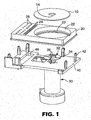
- FIG. 1 and 2 A portion of one illustrative system is depicted in Figures 1 and 2 .
- the depicted portion of the system includes a sample processing device 10 that may preferably be provided in a disc-shaped format such as that depicted.
- suitable disc-shaped devices 10 may be found in, for example, U.S. Provisional Patent Application Serial No. 60/214642 filed on June 28, 2000 and titled SAMPLE PROCESSING DEVICES, SYSTEMS AND METHODS (Attorney Docket No. 55266USA99.003) and U.S. Provisional Patent Application Serial No. 60/237151 filed on even date herewith and titled SAMPLE PROCESSING DEVICES, SYSTEMS AND METHODS (Attorney Docket No.
- processing devices may also be used in connection with the present invention, although they may preferably be modified to incorporate features conducive to automated loading and/or unloading, as well as automated processing.
- examples of some potentially useable rotating processing devices include, but are not limited to those described in, e.g., U.S. Patent Nos. 5,160,702 (Kopf-Sill et al. ); 5,585,069 (Zanzucchi et al. ); 6,030,581 (Virtanen ); and 6,063589 (Kellog et al. ); as well as in International Publication No. WO 00/40750 (Orlefors et al. ).
- a platform 20 is also provided and includes retention structure 22 on its upper surface that is capable of retaining the processing device 10 proximate the upper surface of the platform 20 while the processing device 10 is rotating.
- the retention structure 22 may preferably be slightly larger than the processing device 10 to allow clearance for the processing device 10 to rotate within the retention structure 22. It may be preferable, but not required, that the retention structure 22 also be in the same general shape as the thermal processing device 10, e.g., circular for disc-shaped processing device 10.
- the retention structure 22 be provided in the form of a cavity as depicted in Figures 1 and 2 .
- the retention structure on a platform 20 may be provided in the form of, e.g., a series of raised posts or protrusions that cooperate to retain the processing device 10 within a desired area on the upper surface of the platform 20.
- the retention structure may allow for placement and removal of a processing device 10, such as the retention structure 22 illustrated in Figures 1 and 2 .
- a processing device 10 such as the retention structure 22 illustrated in Figures 1 and 2 .
- the platform 20 may be used with multiple processing devices 10 that may be located in and removed from the retention structure as needed.
- such retention structure may allow the user to select a particular processing device 10 for use with the platform 20.
- the retention structure may be used to retain a captive processing device 10 within a specified area on the upper surface of the platform 20.
- a "captive" processing device means that the processing device cannot be top-loaded into the retention structure without removing a portion of the platform 20 or somehow distorting the shape of the processing device 10. A captive processing device would be retained within the retention structure even if the platform 20 were oriented such that the upper surface faced the ground.
- the depicted platform 20 also includes optional sample fluid chambers 24 that may be used as a staging area for sample materials to be introduced onto the processing device 10.
- the fluid chambers 24 may also contain one or more reagents that may be used on the processing device 10.
- the fluid chambers 24 may preferably be arranged in a rectilinear array that is similar in form to arrays of wells found on a standard microtiter plate having, e.g., 96, 384, or more wells.
- the platform 20 also includes fluid chambers 26 to be used to receive processed sample material removed from the processing device 10.
- the fluid chambers 26 may include filter material 27 within the chamber 26 (see Figure 3 ).
- the fluid chambers 26 may also include a drain port 28 opening at the lower surface of the platform 20 such that sample material introduced into the chamber 26 may pass through the fluid chamber 26. If filter material 27 is present within the chamber 26, then the sample material is filtered during its passage through the chamber 26.
- the fluid chambers 26 on the platform 20 may preferably be arranged in a rectilinear array that is similar in form to arrays of wells found on standard microtiter plates. Further, the fluid chambers 26 are also preferably spaced at intervals compatible with a standard microtiter plate such that wells on a standard microtiter plate located beneath the platform 20 would be aligned with any drain ports of the output wells 26. As a result, processed sample materials removed from the device 10 and transferred to the fluid chambers 26 could be passed through the drain ports of the fluid chambers 26 and into the wells on a standard microtiter plate for additional processing using conventional equipment and procedures.
- a support carriage 40 including alignment structure 42 for receiving the platform 20.
- the support carriage 40 may preferably include an opening 44 to allow for passage of processed sample materials from the fluid chambers 26 to a standard microtiter plate located beneath the support carriage 40.
- the alignment structure 42 may include sloped surfaces as depicted to assist in guiding the platform 20 into position on the support carriage 40.
- a spindle 30 is also depicted in Figures 1 and 2 that can be used to rotate the processing device 10 to facilitate processing of the sample materials located thereon.
- the spindle 30 preferably extends upward through the support carriage 40 and through a spindle opening 23 in the retention structure 22 of the platform 20 (when the plate 20 is located on the carriage 40).
- a chuck 32 adapted to mate with the processing device 10 is preferably provided on the end of the spindle 30.
- the chuck 32 preferably includes a support plate 34 adapted to support the device 10 and at least one, preferably multiple, locking arms 36 in the form of levers that swing outward to retain the device 10 on the chuck 32 as the spindle 30 rotates.
- the arms 36 may preferably be weighted (or otherwise constructed) such that when the spindle 30 is not rotating, the arms 36 are retracted to allow for placement and removal of the device 10 without hindrance from the arms 36.
- a "transfer site” as used herein, is a location at a fixed position relative to the stationary fluid chambers 26. It may be preferred that the stationary fluid chambers 26 and the transfer site 25 be positioned according to a common reference system, e.g., on a rectilinear grid, according to polar coordinates, etc. It may further be preferred that all of the sample fluid chambers 24, stationary fluid chambers 26, transfer site 25 and the location at which loading chambers 16 are positioned for loading be defined by a common reference system.
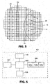
- FIG. 4 one example of a suitable reference system is depicted in which the stationary fluid chambers 26 are located at intersection points on a rectilinear grid, while the transfer site 25 is located at another of the intersection points on the grid. Because the processing device 10 rotates within the retention structure on the platform, different process chambers 12 on the processing device 10 can be indexed into position at the transfer site 25. It may also be preferred that any sample fluid chambers 24, as well as loading chambers 16 on the processing device 10 be positioned at locations defined by a rectilinear array.
- Positioning of the processing device 10 to accomplish, e.g., providing the processing chambers 12 on the processing device 10 at the transfer site 25 may be accomplished by any suitable technique.
- a variety of registration systems and methods are discussed in, e.g., U.S. Provisional Patent Application Serial No. 60/214,642 filed on June 28, 2000 and titled SAMPLE PROCESSING DEVICES, SYSTEMS AND METHODS (Attorney Docket No. 55266USA99.003).
- FIG. 1 and 2 One example of a registration system including complementary structures is depicted in Figures 1 and 2 , where one or more of the arms 36 may cooperate with a keyed slot 14 on the device 10 for registering the rotational position of the processing device 10 on the spindle 30 and, therefore, within the retention structure 22 on the platform 20.
- Such structure can be used to fix the rotational position of the processing device 10 on the spindle 30, provided for accurate indexing of the processing device 10 to put the various features on the processing device 10 in the desired positions.
- the apparatus depicted in Figures 1 and 2 may preferably be used in connection with a variety of transfer devices available from a variety of manufacturers including, but not limited to: Beckman Coulter, Inc. (Fullerton, California), Packard Instrument Company (Meriden, Connecticut), Tomtec (Hamden, Connecticut), MWG-Biotech Inc. (High Point, North Carolina), and Qiagen (Valencia, California).
- Such automated transfer devices typically include pick-and place robotic technology and can be outfitted with a processing station including the support carriage 40 and spindle 30 adapted to receive a platform 20 and associated thermal processing device 10.
- FIG. 5 One such system is depicted in Figure 5 and includes a controller 100, transfer device 102, supplies 104 (which may include, e.g., platforms, thermal processing devices, pipette tips, cleanup materials, sample materials, etc.), a processing station 106 (including, e.g., a support carriage 106a, spindle 106b, and source of electromagnetic radiation 106c) and an unloading station 108. All of these components may preferably be located within a workspace 101.
- supplies 104 which may include, e.g., platforms, thermal processing devices, pipette tips, cleanup materials, sample materials, etc.
- a processing station 106 including, e.g., a support carriage 106a, spindle 106b, and source of electromagnetic radiation 106c
- an unloading station 108 All of these components may preferably be located within a workspace 101.
- the processing station 106 can be loaded with the necessary materials from supplies 104 (e.g., a platform, sample materials, processing device, etc.) using the transfer device 102. Sample materials can then be processed at the processing station 106, with the transfer device 102 being used to transfer sample materials to the desired locations (e.g., from sample fluid chambers on the platform to loading chambers on a processing device and/or from process chambers on the processing device to stationary fluid chambers on the platform, etc.).
- supplies 104 e.g., a platform, sample materials, processing device, etc.
- Sample materials can then be processed at the processing station 106, with the transfer device 102 being used to transfer sample materials to the desired locations (e.g., from sample fluid chambers on the platform to loading chambers on a processing device and/or from process chambers on the processing device to stationary fluid chambers on the platform, etc.).
- the platform After processing at the processing station 106, the platform (with processed sample material) may be moved to, e.g., the unloading station 108 using the transfer device 102, where the processed sample materials may cleaned up using supplies 104 (delivered by the transfer device 102). The sample materials may then be transferred to a standard microtiter plate at the unloading station 108 for further processing of the sample materials.
- the processing station 106 in the form of one of the systems described in, e.g., U.S. Provisional Patent Application Serial No. 60/214,642 filed on June 28, 2000 and titled SAMPLE PROCESSING DEVICES, SYSTEMS AND METHODS (Attorney Docket No. 55266USA99.003) (see, e.g., Figure 9 and the corresponding description in that application) or U.S. Provisional Patent Application Serial No. 60/237151 filed on even date herewith and titled SAMPLE PROCESSING DEVICES, SYSTEMS AND METHODS (Attorney Docket No. 56047USA29).
- the platforms of the present invention may be provided with only a retention structure adapted to receive a rotating processing device, i.e., in the absence of any fluid chambers for staging sample materials or receiving processed sample materials from the processing devices.
- the rectilinear shape of the preferred platforms allows the rotating processing devices to be used in largely conventional robotic transfer devices.
- the filtered sample materials can then be deposited in the wells of, e.g., standard microtiter plates for conventional processing. Examples of some fluid transfer apparatus that may include materials to clean up samples are described in, e.g., U.S. Patent No. 6,048,457 (Kopaciewicz et al. ).
- the depicted apparatus is useful in those systems and methods in which vacuum is used to remove the processed sample materials from the platform 120.
- the apparatus includes a platform 120, a vacuum manifold collar 150, and a manifold base 170 in between which a standard microtiter plate 160 is located when the collar 150 and base 170 are assembled. Together, the vacuum manifold collar 150 and manifold base 170 provide a vacuum manifold useful in extracting sample material from the platform 120 and transferring it to the microtiter plate 160 for processing using conventional processes and equipment.
- the platform 120 includes retention structure 122 similar to that described with respect to platform 20 above.
- a spindle opening 123 is included within the retention structure 122 to receive a spindle adapted to rotate a processing device located therein (not shown).
- the platform 120 also includes optional sample fluid chambers 124 that may be used as a staging area for samples to be introduced onto a processing device.
- the fluid chambers 124 may also contain one or more reagents.
- the fluid chambers 124 may preferably be arranged in a rectilinear array that is similar in form to arrays of wells on a standard microtiter plate.
- the platform 120 also includes stationary fluid chambers 126 to be used to receive processed sample material removed from a processing device.
- the fluid chambers 126 may include filter material.
- the fluid chambers 126 on the platform 120 may preferably be arranged in a rectilinear array that is similar in form to arrays of wells found on standard microtiter plates.
- the fluid chambers 126 are also preferably spaced at intervals compatible with the spacing of the wells 162 on the microtiter plate 160 such that each of the fluid chambers 126 is located above one of the wells 162 in the microtiter plate 160. It may be preferred that the fluid chambers 126 include extended drain ports 128 adapted to extend at least partially into the microtiter plate wells 162. The extended drain ports 128 may assist in preventing cross-contamination during the transfer of materials from the fluid chambers 126 on the platform 120 to the microtiter plate wells 162.
- the vacuum manifold collar 150 preferably includes a seat 152 adapted to receive the lower surface of platform 120.
- a gasket 156 may preferably be located within the seat 152 to assist in sealing around the lower surface of platform 120 when a vacuum is supplied to the manifold.
- the collar 150 also includes an opening 154 through which the extended drain ports 128 on the fluid chambers 126 extend when the apparatus is assembled.
- the manifold base 170 may also preferably include a gasket 172 to assist in sealing the manifold collar 150 to the manifold base 170.
- a vacuum source may be connected to the assembled manifold base 170 and collar 150 to provide a negative pressure that draws processed sample material in the fluid chambers 126 into the microtiter plate wells 162. If the fluid chambers 126 contain filter material, then the processed sample materials in the fluid chambers 126 may be filtered during transfer to the microtiter plate 160. After the transfer is completed, the microtiter plate 160 can be removed and processed using conventional methods and techniques.
Landscapes
- Chemical & Material Sciences (AREA)
- Health & Medical Sciences (AREA)
- Analytical Chemistry (AREA)
- Immunology (AREA)
- Chemical Kinetics & Catalysis (AREA)
- Biochemistry (AREA)
- General Health & Medical Sciences (AREA)
- General Physics & Mathematics (AREA)
- Physics & Mathematics (AREA)
- Pathology (AREA)
- Life Sciences & Earth Sciences (AREA)
- Clinical Laboratory Science (AREA)
- Apparatus Associated With Microorganisms And Enzymes (AREA)
- Automatic Analysis And Handling Materials Therefor (AREA)
- Signal Processing For Digital Recording And Reproducing (AREA)
- Physical Or Chemical Processes And Apparatus (AREA)
- Measuring Or Testing Involving Enzymes Or Micro-Organisms (AREA)
- Analysing Materials By The Use Of Radiation (AREA)
Claims (9)
- Vorrichtung zur Behandlung von Probenmaterialien, die Folgendes umfasst:eine Plattform (20, 120), die eine obere Fläche und eine untere Fläche umfasst;mehrere stationäre Fluidkammern (24, 26, 124, 126), die sich an der oberen Fläche der Plattform (20, 120) öffnen,gekennzeichnet durch
eine Rückhaltekonstruktion (22, 122), die einen Abschnitt der oberen Fläche der Plattform (20, 120) einnimmt, wobei die Rückhaltekonstruktion eine drehbare Mehrkammer-Behandlungseinrichtung (10) in der Nähe der oberen Fläche der Plattform (20, 120) zurückhalten kann. - Vorrichtung nach Anspruch 1, die weiterhin eine innerhalb der Rückhaltekonstruktion (22, 122) befindliche Behandlungseinrichtung (10) umfasst, wobei die Behandlungseinrichtung mehrere Behandlungskammern umfasst, wobei die Behandlungseinrichtung innerhalb der Rückhaltekonstruktion (22, 122) in Drehung versetzt werden kann, um die mehreren Behandlungskammern zu bewegen.
- Vorrichtung nach Anspruch 1 oder Anspruch 2, die weiterhin eine Spindelöffnung (23, 123) umfasst, die durch die obere und die untere Fläche der Plattform (20, 120) verlaufend ausgebildet ist, wobei sich die Spindelöffnung (23, 123) innerhalb der Rückhaltekonstruktion (22, 122) befindet, so dass eine Spindel (30) mit der Mehrkammer-Behandlungseinrichtung in der Nähe der oberen Fläche der Plattform in Kontakt kommen und sie in Drehung versetzen kann.
- Vorrichtung nach Anspruch 1 oder Anspruch 2, wobei die Rückhaltekonstruktion (22, 122) einen in der oberen Fläche der Plattform (20, 120) ausgebildeten Hohlraum umfasst.
- Vorrichtung nach Anspruch 1 oder Anspruch 2, wobei mindestens einige der mehreren stationären Fluidkammern (24, 26, 124, 126) ferner Filtermaterial umfassen.
- Vorrichtung nach Anspruch 1 oder Anspruch 2, wobei die mehreren stationären Fluidkammern (24, 26, 124, 126) in einer geradlinigen Anordnung auf der oberen Fläche der Plattform (20, 120) vorgesehen sind.
- Vorrichtung nach Anspruch 6, wobei mindestens eine der Behandlungskammern auf der Behandlungseinrichtung an einer Transferstelle in der Nähe der oberen Fläche der Plattform (20, 120) positioniert ist, wobei die Position der Transferstelle im Verhältnis zu den stationären Fluidkammern fixiert ist.
- Vorrichtung nach Anspruch 7, die ferner eine ergänzende Registrieranordnung auf der Plattform und der Behandlungseinrichtung umfasst, wobei die ergänzende Registrieranordnung dazu dient, die mindestens eine Behandlungskammer an der durch die geradlinige Anordnung der stationären Fluidkammern definierten Position zu justieren, wenn die Behandlungseinrichtung stationär ist.
- Verfahren zur Behandlung von Probenmaterial, wobei das Verfahren Folgendes umfasst:Bereitstellen einer Plattform (20, 120), die eine obere Fläche und eine untere Fläche, mehrere stationäre Fluidkammern (24, 26, 124, 126), die sich an der oberen Fläche der Plattform öffnen, sowie eine Rückhaltekonstruktion (22, 122) umfasst, die einen Abschnitt der oberen Fläche der Plattform (20, 120) einnimmt;Bereitstellen einer Behandlungseinrichtung (10) in der Rückhaltekonstruktion (22, 122) in der Nähe der oberen Fläche der Plattform, wobei die Behandlungseinrichtung (10) mehrere Behandlungskammern umfasst;Bereitstellen von Probenmaterial in mehreren der mehreren Behandlungskammern auf der Behandlungseinrichtung (10);Zuführen von Energie zu den Probenmaterial enthaltenden Behandlungskammern, um die Temperatur der Probenmaterialien in den Behandlungskammern zu erhöhen; undDrehen der Behandlungseinrichtung (10) um eine Drehachse innerhalb der Rückhaltekonstruktion (22, 122) während der Energiezufuhr, wobei die Temperatur der Probenmaterialien in den Behandlungskammern während der Drehung der Behandlungseinrichtung (10) kontrolliert wird, um die Probenmaterialien zu behandeln.
Applications Claiming Priority (3)
| Application Number | Priority Date | Filing Date | Title |
|---|---|---|---|
| US677805 | 2000-10-02 | ||
| US09/677,805 US6855553B1 (en) | 2000-10-02 | 2000-10-02 | Sample processing apparatus, methods and systems |
| PCT/US2001/029253 WO2002039125A2 (en) | 2000-10-02 | 2001-09-18 | Sample processing apparatus, methods and systems |
Publications (2)
| Publication Number | Publication Date |
|---|---|
| EP1322962A2 EP1322962A2 (de) | 2003-07-02 |
| EP1322962B1 true EP1322962B1 (de) | 2010-11-24 |
Family
ID=24720183
Family Applications (1)
| Application Number | Title | Priority Date | Filing Date |
|---|---|---|---|
| EP01986966A Expired - Lifetime EP1322962B1 (de) | 2000-10-02 | 2001-09-18 | Vorrichtung, verfahren und verwendung zur behandlung von proben |
Country Status (8)
| Country | Link |
|---|---|
| US (1) | US6855553B1 (de) |
| EP (1) | EP1322962B1 (de) |
| JP (1) | JP2004524513A (de) |
| AT (1) | ATE489635T1 (de) |
| AU (2) | AU3922602A (de) |
| CA (1) | CA2423580A1 (de) |
| DE (1) | DE60143531D1 (de) |
| WO (1) | WO2002039125A2 (de) |
Families Citing this family (12)
| Publication number | Priority date | Publication date | Assignee | Title |
|---|---|---|---|---|
| TW200303304A (en) | 2002-02-18 | 2003-09-01 | Astrazeneca Ab | Chemical compounds |
| US7122155B2 (en) * | 2002-07-16 | 2006-10-17 | Mcgill University | Electron microscopy cell fraction sample preparation robot |
| AU2002952797A0 (en) * | 2002-11-20 | 2002-12-05 | Bio-Molecular Holdings Pty Limited | Centrifugal device and method using same |
| DE10338136A1 (de) * | 2003-08-15 | 2005-03-24 | European Molecular Biology Laboratory | Zentrifuge und ein Träger zur Verwendung in einer Zentrifuge |
| WO2005038041A2 (en) * | 2003-10-16 | 2005-04-28 | Third Wave Technologies, Inc. | Direct nucleic acid detection in bodily fluids |
| SE0400208D0 (sv) | 2004-02-02 | 2004-02-02 | Astrazeneca Ab | Chemical compounds |
| JP2008518621A (ja) * | 2004-11-03 | 2008-06-05 | サード・ウェーブ・テクノロジーズ・インク | 一段階検出アッセイ法 |
| US7832292B2 (en) * | 2006-05-19 | 2010-11-16 | Npe Systems, Inc. | Polar coordinate positioning system |
| KR101419980B1 (ko) | 2008-03-15 | 2014-07-15 | 홀로직, 인크. | 증폭 반응 도중에 핵산 분자를 분석하기 위한 조성물 및 방법 |
| ES2653916T3 (es) | 2011-03-08 | 2018-02-09 | Universite Laval | Dispositivo centrípeto fluídico |
| USD799715S1 (en) | 2015-10-23 | 2017-10-10 | Gene POC, Inc. | Fluidic centripetal device |
| TWI738328B (zh) * | 2017-09-28 | 2021-09-01 | 美商伊路米納有限公司 | 流體施配器總成與用於將流體施配至流體匣中的方法 |
Family Cites Families (33)
| Publication number | Priority date | Publication date | Assignee | Title |
|---|---|---|---|---|
| US3767364A (en) * | 1971-07-30 | 1973-10-23 | Sherwood Medical Ind Inc | Reagent pipette system |
| GB1413987A (en) | 1972-03-15 | 1975-11-12 | Hall Thermotank Int Ltd | Heat exchangers |
| US4236894A (en) * | 1979-08-30 | 1980-12-02 | Hycel, Inc. | Readout circuit in an automatic chemical testing apparatus |
| US4284602A (en) | 1979-12-10 | 1981-08-18 | Immutron, Inc. | Integrated fluid manipulator |
| JPS6319558A (ja) | 1986-07-11 | 1988-01-27 | Konica Corp | 血液検査方法及び装置 |
| US5698450A (en) * | 1986-10-14 | 1997-12-16 | Ringrose; Anthony | Method for measuring antigens or antibodies in biological fluids |
| JPS6441861A (en) * | 1987-08-07 | 1989-02-14 | Shimadzu Corp | Sample distribution |
| FR2634893B1 (fr) * | 1988-07-28 | 1990-09-14 | Guigan Jean | Laboratoire miniature pour la realisation d'analyses biologiques par reaction chimique a partir d'un echantillon de sang |
| US5160702A (en) | 1989-01-17 | 1992-11-03 | Molecular Devices Corporation | Analyzer with improved rotor structure |
| JPH0348770A (ja) * | 1989-07-18 | 1991-03-01 | Fuji Photo Film Co Ltd | 生化学分析装置 |
| US5219526A (en) * | 1990-04-27 | 1993-06-15 | Pb Diagnostic Systems Inc. | Assay cartridge |
| US5425918A (en) * | 1990-07-18 | 1995-06-20 | Australian Biomedical Corporation | Apparatus for automatic tissue staining for immunohistochemistry |
| JP3194601B2 (ja) * | 1991-10-02 | 2001-07-30 | オリンパス光学工業株式会社 | 自動分析方法および自動分析装置 |
| JP3024375B2 (ja) * | 1992-07-31 | 2000-03-21 | 味の素株式会社 | 自動前処理装置 |
| DE59410388D1 (de) * | 1993-04-23 | 2004-10-21 | Roche Diagnostics Gmbh | Diskette mit kreisförmig angeordneten Testelementen |
| US5585069A (en) | 1994-11-10 | 1996-12-17 | David Sarnoff Research Center, Inc. | Partitioned microelectronic and fluidic device array for clinical diagnostics and chemical synthesis |
| US5679309A (en) * | 1995-12-14 | 1997-10-21 | Beckman Instruments, Inc. | Automated random access analyzer |
| JPH09189704A (ja) * | 1996-01-10 | 1997-07-22 | Hitachi Ltd | 自動化学分析装置 |
| US5814276A (en) * | 1996-04-25 | 1998-09-29 | Riggs; Robert C. | Automated blood sample processing system |
| JPH1019884A (ja) * | 1996-06-28 | 1998-01-23 | Toa Medical Electronics Co Ltd | 遠心分離式血液分析計 |
| US6720186B1 (en) * | 1998-04-03 | 2004-04-13 | Symyx Technologies, Inc. | Method of research for creating and testing novel catalysts, reactions and polymers |
| US6048457A (en) | 1997-02-26 | 2000-04-11 | Millipore Corporation | Cast membrane structures for sample preparation |
| EP0968434A2 (de) | 1997-02-28 | 2000-01-05 | Burstein Laboratories, Inc. | Labor in einer platte |
| EP0983504A2 (de) | 1997-05-23 | 2000-03-08 | Gamera Bioscience Corporation | Verfahren und vorrichtungen zur benutzung der zentripetalbeschleunigung für die bewegung von flüssigkeiten in einem mikrofluidiksystem |
| US6121054A (en) | 1997-11-19 | 2000-09-19 | Trega Biosciences, Inc. | Method for separation of liquid and solid phases for solid phase organic syntheses |
| US6133045A (en) * | 1998-02-27 | 2000-10-17 | Hamilton Company | Automated sample treatment system: apparatus and method |
| US6413780B1 (en) * | 1998-10-14 | 2002-07-02 | Abbott Laboratories | Structure and method for performing a determination of an item of interest in a sample |
| GB9828785D0 (en) | 1998-12-30 | 1999-02-17 | Amersham Pharm Biotech Ab | Sequencing systems |
| US7312084B2 (en) * | 2001-07-13 | 2007-12-25 | Ortho-Clinical Diagnostics, Inc. | Tandem incubator for clinical analyzer |
| US7402282B2 (en) * | 2001-07-20 | 2008-07-22 | Ortho-Clinical Diagnostics, Inc. | Auxiliary sample supply for a clinical analyzer |
| US20030040117A1 (en) * | 2001-07-27 | 2003-02-27 | Devlin William Jackson | Increasing throughput in an automatic clinical analyzer by partitioning assays according to type |
| US7279130B2 (en) * | 2001-08-13 | 2007-10-09 | Bayer Healthcare Llc | Sensor dispensing instrument having an activation mechanism and methods of using the same |
| US7285245B2 (en) * | 2001-09-05 | 2007-10-23 | Fujifilm Corporation | Biochemical analysis method and apparatus |
-
2000
- 2000-10-02 US US09/677,805 patent/US6855553B1/en not_active Expired - Fee Related
-
2001
- 2001-09-18 JP JP2002541399A patent/JP2004524513A/ja active Pending
- 2001-09-18 WO PCT/US2001/029253 patent/WO2002039125A2/en not_active Ceased
- 2001-09-18 AU AU3922602A patent/AU3922602A/xx active Pending
- 2001-09-18 EP EP01986966A patent/EP1322962B1/de not_active Expired - Lifetime
- 2001-09-18 DE DE60143531T patent/DE60143531D1/de not_active Expired - Lifetime
- 2001-09-18 AU AU2002239226A patent/AU2002239226B2/en not_active Ceased
- 2001-09-18 CA CA002423580A patent/CA2423580A1/en not_active Abandoned
- 2001-09-18 AT AT01986966T patent/ATE489635T1/de not_active IP Right Cessation
Also Published As
| Publication number | Publication date |
|---|---|
| CA2423580A1 (en) | 2002-05-16 |
| JP2004524513A (ja) | 2004-08-12 |
| AU2002239226B2 (en) | 2006-06-22 |
| ATE489635T1 (de) | 2010-12-15 |
| DE60143531D1 (de) | 2011-01-05 |
| AU3922602A (en) | 2002-05-21 |
| EP1322962A2 (de) | 2003-07-02 |
| WO2002039125A2 (en) | 2002-05-16 |
| US6855553B1 (en) | 2005-02-15 |
| WO2002039125A3 (en) | 2003-03-27 |
Similar Documents
| Publication | Publication Date | Title |
|---|---|---|
| EP1379852B1 (de) | Multiformat-probenprozessierungsvorrichtungen, -verfahren und -systeme | |
| AU2002239226B2 (en) | Sample processing apparatus, methods and systems | |
| EP1899063B1 (de) | Nachgiebige scheiben zur behandlung von mikrofluidproben | |
| US9701957B2 (en) | Reagent holder, and kits containing same | |
| US6875619B2 (en) | Microfluidic devices comprising biochannels | |
| EP1296764B1 (de) | Verfahren zur probenverarbeitung | |
| EP2409767B1 (de) | Modulare Kartusche, System und Verfahren zur automatischen medizinischen Diagnose | |
| US9108193B2 (en) | Collection/extraction container for biological material in forensic samples | |
| AU2009201529B2 (en) | Apparatus For Polynucleotide Detection and Quantitation | |
| EP2107944B1 (de) | Verbesserte probenverarbeitungsvorrichtungen, -systeme und -verfahren | |
| WO2003066907A1 (en) | Seal for microtiter plate and methods of use thereof | |
| EP1904234B1 (de) | Kassette zur automatisierten medizinischen diagnose | |
| US20050009101A1 (en) | Microfluidic devices comprising biochannels | |
| AU2002239226A1 (en) | Sample processing apparatus, methods and systems | |
| CN101094722A (zh) | 用于将微流体装置与流体处理装置接口的装置和方法 | |
| EP4124385A1 (de) | Anordnung und verfahren zur kombinierten reinigung und amplifikation von nukleinsäuren | |
| WO2009074177A1 (en) | Forensic sample processor | |
| Meldrum et al. | ACAPELLA-5K, a high-throughput automated genome and chemical analysis system | |
| US20240393359A1 (en) | Method for processing and analyzing sample in molecular diagnostic system | |
| WO2024173711A2 (en) | Centrifugal microfluidic systems and methods for dna methylation sample preparation | |
| WO2007048832A1 (en) | Apparatus for processing biological material |
Legal Events
| Date | Code | Title | Description |
|---|---|---|---|
| PUAI | Public reference made under article 153(3) epc to a published international application that has entered the european phase |
Free format text: ORIGINAL CODE: 0009012 |
|
| 17P | Request for examination filed |
Effective date: 20030411 |
|
| AK | Designated contracting states |
Designated state(s): AT BE CH CY DE DK ES FI FR GB GR IE IT LI LU MC NL PT SE TR |
|
| AX | Request for extension of the european patent |
Extension state: AL LT LV MK RO SI |
|
| 17Q | First examination report despatched |
Effective date: 20091023 |
|
| GRAP | Despatch of communication of intention to grant a patent |
Free format text: ORIGINAL CODE: EPIDOSNIGR1 |
|
| GRAS | Grant fee paid |
Free format text: ORIGINAL CODE: EPIDOSNIGR3 |
|
| GRAA | (expected) grant |
Free format text: ORIGINAL CODE: 0009210 |
|
| AK | Designated contracting states |
Kind code of ref document: B1 Designated state(s): AT BE CH CY DE DK ES FI FR GB GR IE IT LI LU MC NL PT SE TR |
|
| REG | Reference to a national code |
Ref country code: GB Ref legal event code: FG4D |
|
| REG | Reference to a national code |
Ref country code: CH Ref legal event code: EP |
|
| REG | Reference to a national code |
Ref country code: IE Ref legal event code: FG4D |
|
| REF | Corresponds to: |
Ref document number: 60143531 Country of ref document: DE Date of ref document: 20110105 Kind code of ref document: P |
|
| REG | Reference to a national code |
Ref country code: NL Ref legal event code: VDEP Effective date: 20101124 |
|
| PG25 | Lapsed in a contracting state [announced via postgrant information from national office to epo] |
Ref country code: SE Free format text: LAPSE BECAUSE OF FAILURE TO SUBMIT A TRANSLATION OF THE DESCRIPTION OR TO PAY THE FEE WITHIN THE PRESCRIBED TIME-LIMIT Effective date: 20101124 Ref country code: CY Free format text: LAPSE BECAUSE OF FAILURE TO SUBMIT A TRANSLATION OF THE DESCRIPTION OR TO PAY THE FEE WITHIN THE PRESCRIBED TIME-LIMIT Effective date: 20101124 Ref country code: AT Free format text: LAPSE BECAUSE OF FAILURE TO SUBMIT A TRANSLATION OF THE DESCRIPTION OR TO PAY THE FEE WITHIN THE PRESCRIBED TIME-LIMIT Effective date: 20101124 Ref country code: NL Free format text: LAPSE BECAUSE OF FAILURE TO SUBMIT A TRANSLATION OF THE DESCRIPTION OR TO PAY THE FEE WITHIN THE PRESCRIBED TIME-LIMIT Effective date: 20101124 Ref country code: PT Free format text: LAPSE BECAUSE OF FAILURE TO SUBMIT A TRANSLATION OF THE DESCRIPTION OR TO PAY THE FEE WITHIN THE PRESCRIBED TIME-LIMIT Effective date: 20110324 Ref country code: FI Free format text: LAPSE BECAUSE OF FAILURE TO SUBMIT A TRANSLATION OF THE DESCRIPTION OR TO PAY THE FEE WITHIN THE PRESCRIBED TIME-LIMIT Effective date: 20101124 |
|
| PG25 | Lapsed in a contracting state [announced via postgrant information from national office to epo] |
Ref country code: GR Free format text: LAPSE BECAUSE OF FAILURE TO SUBMIT A TRANSLATION OF THE DESCRIPTION OR TO PAY THE FEE WITHIN THE PRESCRIBED TIME-LIMIT Effective date: 20110225 |
|
| PG25 | Lapsed in a contracting state [announced via postgrant information from national office to epo] |
Ref country code: ES Free format text: LAPSE BECAUSE OF FAILURE TO SUBMIT A TRANSLATION OF THE DESCRIPTION OR TO PAY THE FEE WITHIN THE PRESCRIBED TIME-LIMIT Effective date: 20110307 Ref country code: BE Free format text: LAPSE BECAUSE OF FAILURE TO SUBMIT A TRANSLATION OF THE DESCRIPTION OR TO PAY THE FEE WITHIN THE PRESCRIBED TIME-LIMIT Effective date: 20101124 |
|
| PG25 | Lapsed in a contracting state [announced via postgrant information from national office to epo] |
Ref country code: DK Free format text: LAPSE BECAUSE OF FAILURE TO SUBMIT A TRANSLATION OF THE DESCRIPTION OR TO PAY THE FEE WITHIN THE PRESCRIBED TIME-LIMIT Effective date: 20101124 |
|
| PLBE | No opposition filed within time limit |
Free format text: ORIGINAL CODE: 0009261 |
|
| STAA | Information on the status of an ep patent application or granted ep patent |
Free format text: STATUS: NO OPPOSITION FILED WITHIN TIME LIMIT |
|
| 26N | No opposition filed |
Effective date: 20110825 |
|
| REG | Reference to a national code |
Ref country code: DE Ref legal event code: R097 Ref document number: 60143531 Country of ref document: DE Effective date: 20110825 |
|
| PG25 | Lapsed in a contracting state [announced via postgrant information from national office to epo] |
Ref country code: IT Free format text: LAPSE BECAUSE OF FAILURE TO SUBMIT A TRANSLATION OF THE DESCRIPTION OR TO PAY THE FEE WITHIN THE PRESCRIBED TIME-LIMIT Effective date: 20101124 |
|
| PG25 | Lapsed in a contracting state [announced via postgrant information from national office to epo] |
Ref country code: MC Free format text: LAPSE BECAUSE OF NON-PAYMENT OF DUE FEES Effective date: 20110930 |
|
| REG | Reference to a national code |
Ref country code: CH Ref legal event code: PL |
|
| GBPC | Gb: european patent ceased through non-payment of renewal fee |
Effective date: 20110918 |
|
| REG | Reference to a national code |
Ref country code: IE Ref legal event code: MM4A |
|
| REG | Reference to a national code |
Ref country code: FR Ref legal event code: ST Effective date: 20120531 |
|
| REG | Reference to a national code |
Ref country code: DE Ref legal event code: R119 Ref document number: 60143531 Country of ref document: DE Effective date: 20120403 |
|
| PG25 | Lapsed in a contracting state [announced via postgrant information from national office to epo] |
Ref country code: DE Free format text: LAPSE BECAUSE OF NON-PAYMENT OF DUE FEES Effective date: 20120403 Ref country code: CH Free format text: LAPSE BECAUSE OF NON-PAYMENT OF DUE FEES Effective date: 20110930 Ref country code: LI Free format text: LAPSE BECAUSE OF NON-PAYMENT OF DUE FEES Effective date: 20110930 Ref country code: IE Free format text: LAPSE BECAUSE OF NON-PAYMENT OF DUE FEES Effective date: 20110918 |
|
| PG25 | Lapsed in a contracting state [announced via postgrant information from national office to epo] |
Ref country code: FR Free format text: LAPSE BECAUSE OF NON-PAYMENT OF DUE FEES Effective date: 20110930 Ref country code: GB Free format text: LAPSE BECAUSE OF NON-PAYMENT OF DUE FEES Effective date: 20110918 |
|
| PG25 | Lapsed in a contracting state [announced via postgrant information from national office to epo] |
Ref country code: LU Free format text: LAPSE BECAUSE OF NON-PAYMENT OF DUE FEES Effective date: 20110918 |
|
| PG25 | Lapsed in a contracting state [announced via postgrant information from national office to epo] |
Ref country code: TR Free format text: LAPSE BECAUSE OF FAILURE TO SUBMIT A TRANSLATION OF THE DESCRIPTION OR TO PAY THE FEE WITHIN THE PRESCRIBED TIME-LIMIT Effective date: 20101124 |