EP1323865B1 - Construction d' équilibrage - Google Patents
Construction d' équilibrage Download PDFInfo
- Publication number
- EP1323865B1 EP1323865B1 EP02028634A EP02028634A EP1323865B1 EP 1323865 B1 EP1323865 B1 EP 1323865B1 EP 02028634 A EP02028634 A EP 02028634A EP 02028634 A EP02028634 A EP 02028634A EP 1323865 B1 EP1323865 B1 EP 1323865B1
- Authority
- EP
- European Patent Office
- Prior art keywords
- bearing
- sliding
- construction according
- compensating
- turning
- Prior art date
- Legal status (The legal status is an assumption and is not a legal conclusion. Google has not performed a legal analysis and makes no representation as to the accuracy of the status listed.)
- Expired - Lifetime
Links
Images

Classifications
-
- E—FIXED CONSTRUCTIONS
- E01—CONSTRUCTION OF ROADS, RAILWAYS, OR BRIDGES
- E01D—CONSTRUCTION OF BRIDGES, ELEVATED ROADWAYS OR VIADUCTS; ASSEMBLY OF BRIDGES
- E01D19/00—Structural or constructional details of bridges
- E01D19/04—Bearings; Hinges
-
- E—FIXED CONSTRUCTIONS
- E01—CONSTRUCTION OF ROADS, RAILWAYS, OR BRIDGES
- E01B—PERMANENT WAY; PERMANENT-WAY TOOLS; MACHINES FOR MAKING RAILWAYS OF ALL KINDS
- E01B2/00—General structure of permanent way
- E01B2/003—Arrangement of tracks on bridges or in tunnels
-
- E—FIXED CONSTRUCTIONS
- E01—CONSTRUCTION OF ROADS, RAILWAYS, OR BRIDGES
- E01D—CONSTRUCTION OF BRIDGES, ELEVATED ROADWAYS OR VIADUCTS; ASSEMBLY OF BRIDGES
- E01D19/00—Structural or constructional details of bridges
- E01D19/04—Bearings; Hinges
- E01D19/042—Mechanical bearings
- E01D19/047—Pot bearings
-
- E—FIXED CONSTRUCTIONS
- E01—CONSTRUCTION OF ROADS, RAILWAYS, OR BRIDGES
- E01D—CONSTRUCTION OF BRIDGES, ELEVATED ROADWAYS OR VIADUCTS; ASSEMBLY OF BRIDGES
- E01D19/00—Structural or constructional details of bridges
- E01D19/04—Bearings; Hinges
- E01D19/048—Bearings being adjustable once installed; Bearings used in incremental launching
-
- E—FIXED CONSTRUCTIONS
- E01—CONSTRUCTION OF ROADS, RAILWAYS, OR BRIDGES
- E01B—PERMANENT WAY; PERMANENT-WAY TOOLS; MACHINES FOR MAKING RAILWAYS OF ALL KINDS
- E01B1/00—Ballastway; Other means for supporting the sleepers or the track; Drainage of the ballastway
- E01B1/002—Ballastless track, e.g. concrete slab trackway, or with asphalt layers
Definitions
- the invention relates to a compensating construction according to the preamble of claim 1.
- Such a compensation construction is known from DE-A-198 06 566.
- This solution is characterized by the fact that even with bridges of greater length, the movements of the joints can be absorbed.
- a compensating plate bridges the gap and in particular the critical end tangent angle of the track, which generates considerable and dangerous lifting forces at the rail supports, is reduced by a multiple.
- An elastomeric body under load behaves like a non-compressible fluid in volume change. It is therefore known to produce elastomeric bodies with concave side surfaces, so that the side surfaces are substantially straight under load. With a correspondingly high load, a rather soft bearing with the possibility of horizontal displacement arises.
- DE-A-27 46 490 describes a solution for road bridges, which is intended to compensate for the elongation of bridge segments by horizontally sliding and rotatable elements. A vertical movement and thus the necessary degree of freedom to allow compression during load changes to railway constructions, however, is not possible with the solution described here.
- the invention is based on the object to provide a compensation structure for railway construction according to the preamble of claim 1, which is particularly durable, without overwriting the available space, yet the cost, especially the maintenance costs, should be low ,
- the compensation structure according to the invention is characterized by the realization of a pivot bearing, wherein the pivot bearing is combined with a sliding bearing.
- a plain bearing can be extremely durable when using suitable materials such as UHMW, whereby the combination ensures that the sliding disk is always guided parallel to the sliding plate.
- a pivot bearing is basically able to compensate for inclinations.
- the pivot bearing may be formed, for example, as Cincinnatikippgleitlager.
- Such a bearing has a joint socket and a joint head, which fit together and are well pressure resistant.
- tilting movements of the compensating plate do not disturb the sliding movement due to the immediately adjacent arrangement of pivot bearings and plain bearings, but can be absorbed harmoniously and without delay by the rotary bearing.
- the hood body pivot bearing and plain bearing connects and rotational movements can be intercepted precisely guided both in the rail longitudinal direction and in the rail transverse direction.
- the combined rotary and sliding bearing according to the invention provides a low-wear and precise guidance, so that a biaxial angular adjustment is made possible.
- a pivot axis of the pivot bearing according to the invention preferably extends around a horizontal direction, while the other axis of rotation extends around the other horizontal direction.
- the combination of a pivot bearing with a plain bearing opens up the possibility of height adjustment.
- Another advantage of the inventive combination of the pivot bearing with the plain bearing is the protective effect of the hood body.
- the hood body extends almost semicircular and forms a hood so that it is held captive on the pivot bearing.
- the cover angle is preferably 120 ° to 180 ° and in particular about 160 °.
- the height adjustment of the pivot bearing also makes it possible to keep equal in bearing pressure of all necessary for the support of the balance plate plain bearing.
- the wear of the plain bearings is made uniform, so that the maintenance costs decrease.
- an elastic body is additionally provided below the slide bearing, which projects beyond the pivot bearing horizontally.
- the elastic body is torque-safe and allows it to compensate for the response delay of the pivot bearing so that the entire construction is much more durable.
- the exact configuration of the elastic body can be adapted to the requirements in a wide range.
- an additional vertically horrurchender elastic body may be provided, which also absorbs lateral forces elastic.
- the load introduced into the elastic body is significantly lower, for example by one order of magnitude, than when using pure elastomer bearings.
- the elastic body can also be provided between the compensating plate and the pivot bearing if required, it is in accordance with the invention provided advantageous configuration to integrate the elastic body in the bearing block of the pivot bearing.
- the height required according to the invention is so small that the realization of the compensating construction according to the invention is possible even in the case of scarce on-site dimensioning.
- the height may be 200 mm or even less.
- the ball pressure screw of the NOTEkippgleitlagers is preferably sunk in the bearing body, and the bearing forces are added via adjusting nut of the ball pressure screw, the support nut.
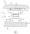
- a compensating structure 10 has in the embodiment shown in FIG. 1 on a balancing plate 12, which is on a plurality of bearings, of which a bearing 14 is shown on a non shown bridge abutment or superstructure end is supported.
- the balance plate 12 is provided on its underside in the areas to be supported with sliding plate 16, which forms part of a sliding bearing 18.
- the sliding bearing 18 also has a sliding disk 20 made of a plastic with low coefficients of friction such as PTFE. It is particularly favorable if the sliding disk 20 consists of ultrahigh molecular weight polyethylene which has a coefficient of friction comparable to PTFE, but is substantially more durable.
- the sliding disk 20 is received on a hood body 22, which supports a sealing lip 24 which extends beyond the sliding disk 20 on the sliding plate 16 is supported.
- the interior thus formed is provided in a manner known per se with lubricant, wherein it is also possible to provide a lubricant supply for the permanent lubrication.
- the hood body 22 is formed to fit a ball pressure screw 26.
- the ball pressure screw 26 and the hood body 22 form condyle and socket of a pivot bearing 28.
- the pivot bearing 28 is height adjustable via an adjustment of the ball pressure screw 26.
- a support nut 30 is provided which projects into a support plate 32 partially and partially supported on the surface of the support plate.
- the support nut 30 has as well as the ball pressure screw 26 has a hexagonal portion 34 and 36, and by adjusting the relative angular position between the ball pressure screw 26 and support nut 30, the height of the pivot bearing 28 is adjustable.
- the angular positions can be adjusted via fixing screws 38 and 40, which are preferably countersunk.
- the bearing 14 according to the invention is provided with an elastic body 42.
- the elastic body 42 extends on the underside of the support plate 40 practically over the entire support plate. In a conventional manner, it consists of elastomeric material and is concave at its edge regions 44 in the unloaded state.
- the underside 46 of the support plate 32 is this formed over the entire surface, while in the embodiment of FIG. 1, a Duchtrittsaus Principleung is provided in extension of the ball pressure screw 26. It is understood that in the embodiment according to FIG. 1, nevertheless, an elastic body can be provided, which then preferably extends annularly or, if necessary, is divided into a plurality of individual elastic bodies.
- the support plate 30 is received together with the elastic body 42 in a bearing body 48.
- the bearing body 48 extends substantially cup-shaped, and the combination of the support plate 32, the elastic body 42 and the bearing body 48 forms a bearing block 50 for the bearing 14th
- a vertical, annular elastic body 52 is additionally provided, which serves for the elastic support of horizontal forces between the support plate 32 and the bearing body 48. Also, the elastic body 52 has in the unloaded state concave side surfaces.
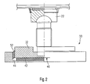
- Fig. 3 From Fig. 3 it can be seen in which way the elastic body 42 and 52 can deform in special load situations.
- the state of both elastic bodies 42 and 52 is shown in the unloaded state.
- the state of the elastic body 42 and 52 is shown in Fig. 3 in the lower region, which is achieved when a load on the bridge by, for example, a train a Slanting the compensating plate initiates.
- a load on the bridge by, for example, a train a Slanting the compensating plate initiates.
- the moments are absorbed both by the elastic body 42 and partially by the elastic body 52, and after response of the pivot bearing 28 takes place in a conventional manner a provision with respect to the recording of moments, but not with respect to the deflection.
- this short-term overshoot makes it possible to reliably prevent the track bearing from being destroyed or at least severely worn by the inclination.
- a particular loading problem with balancing plates for railway bridges is that the load introduction takes place suddenly and then exists as a combined movement, thus requiring both a response of the plain bearing and the rotary bearing. According to the invention exactly this load situation is taken into account by the elastic body.
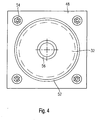
- Fig. 4 is a plan view of the bearing body 48 can be seen.
- the bearing body 48 is fixed with four bolts 54 on the superstructure or the abutment. In a circular recess rests on the elastic body 42 and 52 supported support plate 32nd
- Fig. 4 the recess 56 is further shown, in which the support nut 30 of the ball pressure screw 26 is partially received.
Landscapes
- Engineering & Computer Science (AREA)
- Architecture (AREA)
- Civil Engineering (AREA)
- Structural Engineering (AREA)
- Mechanical Engineering (AREA)
- Bridges Or Land Bridges (AREA)
- Vibration Prevention Devices (AREA)
- Component Parts Of Construction Machinery (AREA)
- Turbine Rotor Nozzle Sealing (AREA)
- Processing Of Stones Or Stones Resemblance Materials (AREA)
- Constituent Portions Of Griding Lathes, Driving, Sensing And Control (AREA)
Claims (11)
- Construction d'équilibrage (10) destinée à surmonter un joint dans la construction ferroviaire, comprenant une plaque d'équilibrage (12) pouvant s'appuyer sur une culée de pont ou contre au moins une extrémité de superstructure du pont et des paliers (14) pour celle-ci sur la culée de pont ou contre l'extrémité de superstructure, au-dessus desquels est montée la plaque d'équilibrage (12), notamment lors de l'enfoncement du pont, les paliers (14) étant conçus en étant mobiles de manière élastique,
caractérisée en ce que
chaque palier (14) comprend un palier pivotant (28) et un palier coulissant (18). - Construction d'équilibrage selon l'une quelconque des revendications précédentes, caractérisée en ce que le palier coulissant (18) est situé entre le palier pivotant (28) et la plaque d'équilibrage (12).
- Construction d'équilibrage selon l'une quelconque des revendications précédentes, caractérisée en ce que le palier pivotant (28) est conçu comme un palier réglable en hauteur.
- Construction d'équilibrage selon l'une quelconque des revendications précédentes, caractérisée en ce que le palier pivotant (28) est conçu comme un appui oscillant-coulissant.
- Construction d'équilibrage selon l'une quelconque des revendications précédentes, caractérisée en ce que le palier coulissant (18) au-dessus du palier pivotant (28) est constitué d'une manière connue en soi d'un disque coulissant (20), qui glisse sur des tôles de glissement (16), le disque coulissant (20) étant fabriqué notamment à partir de polyéthylènes à ultra haut poids moléculaire.
- Construction d'équilibrage selon la revendication 5, caractérisée en ce que le palier coulissant (18) est compartimenté et en particulier, une lèvre d'étanchéité s'étend au-delà du disque coulissant (28) en direction de la tôle de glissement (16) et glisse sur celle-ci.
- Construction d'équilibrage selon l'une quelconque des revendications précédentes, caractérisée en ce qu'un corps de calotte (22) et une vis à bille (26) du palier pivotant (28) forment un joint à bille dont la surface d'appui enferme un angle de 120° à 180°, notamment d'approximativement 160°.
- Construction d'équilibrage selon l'une quelconque des revendications précédentes, caractérisée en ce qu'un corps élastique (42) s'étend sensiblement en forme de plaque ou de couche sous le palier pivotant (28).
- Construction d'équilibrage selon l'une quelconque des revendications précédentes, caractérisée en ce que le palier pivotant (28) comprend une vis à bille (26), qui est logée dans un écrou d'appui (30) par l'intermédiaire duquel le palier pivotant est réglable en hauteur.
- Construction d'équilibrage selon l'une quelconque des revendications précédentes, caractérisée en ce que le corps élastique est conçu comme une partie d'une chaise de palier (50) du palier pivotant (28) et est reçu sensiblement sur toute la surface entre une plaque d'appui (32) et un corps de palier (48).
- Construction d'équilibrage selon l'une quelconque des revendications précédentes, caractérisée en ce que le palier pivotant (28) s'appuie sur le corps élastique qui est constitué en particulier d'élastomère.
Applications Claiming Priority (4)
| Application Number | Priority Date | Filing Date | Title |
|---|---|---|---|
| DE10163422 | 2001-12-21 | ||
| DE10163422 | 2001-12-21 | ||
| DE10244993 | 2002-09-26 | ||
| DE10244993A DE10244993B4 (de) | 2001-12-21 | 2002-09-26 | Ausgleichskonstruktion |
Publications (3)
| Publication Number | Publication Date |
|---|---|
| EP1323865A2 EP1323865A2 (fr) | 2003-07-02 |
| EP1323865A3 EP1323865A3 (fr) | 2004-01-14 |
| EP1323865B1 true EP1323865B1 (fr) | 2006-09-27 |
Family
ID=26010845
Family Applications (1)
| Application Number | Title | Priority Date | Filing Date |
|---|---|---|---|
| EP02028634A Expired - Lifetime EP1323865B1 (fr) | 2001-12-21 | 2002-12-20 | Construction d' équilibrage |
Country Status (3)
| Country | Link |
|---|---|
| EP (1) | EP1323865B1 (fr) |
| AT (1) | ATE340896T1 (fr) |
| DE (1) | DE50208246D1 (fr) |
Families Citing this family (1)
| Publication number | Priority date | Publication date | Assignee | Title |
|---|---|---|---|---|
| CN110055826B (zh) * | 2019-04-28 | 2023-09-22 | 中铁二院工程集团有限责任公司 | 一种路堑齿轨铁路增强型道床结构的构筑方法 |
Family Cites Families (5)
| Publication number | Priority date | Publication date | Assignee | Title |
|---|---|---|---|---|
| DE801730C (de) * | 1948-11-27 | 1951-01-22 | Gutehoffnungshuette Oberhausen | Drehlager fuer Klappbruecken |
| DE2461325B1 (de) * | 1974-12-24 | 1976-04-01 | Kober Ag | Gleitlager fuer Bruecken oder aehnliche Bauwerke |
| DE2746490C3 (de) * | 1977-10-15 | 1982-05-19 | Friedrich Maurer Söhne GmbH & Co KG, 8000 München | Überbrückungsvorrichtung für Dehnungsfugen in Brücken o.dgl. |
| DE19806566C5 (de) * | 1998-02-17 | 2007-04-05 | Stog, Arnulf | Ausgleichplatte für Eisenbahnbrücken |
| US6324795B1 (en) * | 1999-11-24 | 2001-12-04 | Ever-Level Foundation Systems, Inc. | Seismic isolation system between floor and foundation comprising a ball and socket joint and elastic or elastomeric element |
-
2002
- 2002-12-20 AT AT02028634T patent/ATE340896T1/de active
- 2002-12-20 DE DE50208246T patent/DE50208246D1/de not_active Expired - Lifetime
- 2002-12-20 EP EP02028634A patent/EP1323865B1/fr not_active Expired - Lifetime
Also Published As
| Publication number | Publication date |
|---|---|
| DE50208246D1 (de) | 2006-11-09 |
| EP1323865A2 (fr) | 2003-07-02 |
| ATE340896T1 (de) | 2006-10-15 |
| EP1323865A3 (fr) | 2004-01-14 |
Similar Documents
| Publication | Publication Date | Title |
|---|---|---|
| DE102005060375A1 (de) | Gleitpendellager | |
| DE3540128A1 (de) | Elastisch gelagerte schiene fuer schienenfahrzeuge | |
| EP1709248B1 (fr) | Dispositif de deplacement d'une lame d'aiguille ainsi que dispositif a rouleaux pouvant etre regle en hauteur | |
| EP2978897A1 (fr) | Structure de transition et pont de voie ferrée équipé d'une structure de transition de ce type | |
| DE60122908T2 (de) | Paneelbefestigungselement | |
| EP1803964B1 (fr) | Module hybride de rigidité pour isolation de vibrations | |
| AT3270U1 (de) | Lager für bauwerke, sowie brückenlager | |
| EP1323865B1 (fr) | Construction d' équilibrage | |
| DE4219472A1 (de) | Einrichtung zum Lagern von Schienen | |
| EP2501858A1 (fr) | Palier de bâtiment | |
| DE10244993B4 (de) | Ausgleichskonstruktion | |
| DE8916127U1 (de) | Vorrichtung zur federnden Einspannung von Traversen einer Fahrbahnüberbrückungskonstruktion | |
| EP0681985A1 (fr) | Rouleaux de guidage d'une porte coulissante d'ascenseur | |
| EP0155622A2 (fr) | Appui de levage pour transmettre, soulever et/ou baisser des charges lourdes, en particulier des ponts | |
| DE3812878C2 (fr) | ||
| EP1935780A2 (fr) | Appareil de sortie | |
| DE3031173A1 (de) | Hydraulische kolbengleisbremse zum abbremsen von eisenbahnwagen | |
| EP1395709B1 (fr) | Systeme support et support y relatif | |
| EP4085171B1 (fr) | Utilisation d'un appareil d'appui glissant | |
| DE102015217510B4 (de) | Gleitlager-Drehverbindung | |
| DE102022204542B3 (de) | Bauwerksgleitlager | |
| DE102008017323B4 (de) | Topflager für Bauwerke, insbesondere Brückenbauwerke, mit hoher Abriebfestigkeit und dauerhaftem Schutz vor Feuchtigkeit und Feinstpartikeln | |
| DE4339545A1 (de) | Füllkörper für Gleisschwellen | |
| EP1836404A2 (fr) | Appui oscillant a glissement | |
| DE202022002788U1 (de) | Bauwerksgleitlager |
Legal Events
| Date | Code | Title | Description |
|---|---|---|---|
| PUAI | Public reference made under article 153(3) epc to a published international application that has entered the european phase |
Free format text: ORIGINAL CODE: 0009012 |
|
| AK | Designated contracting states |
Designated state(s): AT BE BG CH CY CZ DE DK EE ES FI FR GB GR IE IT LI LU MC NL PT SE SI SK TR |
|
| AX | Request for extension of the european patent |
Extension state: AL LT LV MK RO |
|
| PUAL | Search report despatched |
Free format text: ORIGINAL CODE: 0009013 |
|
| AK | Designated contracting states |
Kind code of ref document: A3 Designated state(s): AT BE BG CH CY CZ DE DK EE ES FI FR GB GR IE IT LI LU MC NL PT SE SI SK TR |
|
| AX | Request for extension of the european patent |
Extension state: AL LT LV MK RO |
|
| 17P | Request for examination filed |
Effective date: 20040710 |
|
| AKX | Designation fees paid |
Designated state(s): AT BE BG CH CY CZ DE DK EE ES FI FR GB GR IE IT LI LU MC NL PT SE SI SK TR |
|
| 17Q | First examination report despatched |
Effective date: 20041209 |
|
| GRAP | Despatch of communication of intention to grant a patent |
Free format text: ORIGINAL CODE: EPIDOSNIGR1 |
|
| GRAS | Grant fee paid |
Free format text: ORIGINAL CODE: EPIDOSNIGR3 |
|
| GRAA | (expected) grant |
Free format text: ORIGINAL CODE: 0009210 |
|
| AK | Designated contracting states |
Kind code of ref document: B1 Designated state(s): AT BE BG CH CY CZ DE DK EE ES FI FR GB GR IE IT LI LU MC NL PT SE SI SK TR |
|
| PG25 | Lapsed in a contracting state [announced via postgrant information from national office to epo] |
Ref country code: IT Free format text: LAPSE BECAUSE OF FAILURE TO SUBMIT A TRANSLATION OF THE DESCRIPTION OR TO PAY THE FEE WITHIN THE PRESCRIBED TIME-LIMIT;WARNING: LAPSES OF ITALIAN PATENTS WITH EFFECTIVE DATE BEFORE 2007 MAY HAVE OCCURRED AT ANY TIME BEFORE 2007. THE CORRECT EFFECTIVE DATE MAY BE DIFFERENT FROM THE ONE RECORDED. Effective date: 20060927 Ref country code: SI Free format text: LAPSE BECAUSE OF FAILURE TO SUBMIT A TRANSLATION OF THE DESCRIPTION OR TO PAY THE FEE WITHIN THE PRESCRIBED TIME-LIMIT Effective date: 20060927 Ref country code: SK Free format text: LAPSE BECAUSE OF FAILURE TO SUBMIT A TRANSLATION OF THE DESCRIPTION OR TO PAY THE FEE WITHIN THE PRESCRIBED TIME-LIMIT Effective date: 20060927 Ref country code: FI Free format text: LAPSE BECAUSE OF FAILURE TO SUBMIT A TRANSLATION OF THE DESCRIPTION OR TO PAY THE FEE WITHIN THE PRESCRIBED TIME-LIMIT Effective date: 20060927 Ref country code: CZ Free format text: LAPSE BECAUSE OF FAILURE TO SUBMIT A TRANSLATION OF THE DESCRIPTION OR TO PAY THE FEE WITHIN THE PRESCRIBED TIME-LIMIT Effective date: 20060927 Ref country code: IE Free format text: LAPSE BECAUSE OF FAILURE TO SUBMIT A TRANSLATION OF THE DESCRIPTION OR TO PAY THE FEE WITHIN THE PRESCRIBED TIME-LIMIT Effective date: 20060927 |
|
| REG | Reference to a national code |
Ref country code: GB Ref legal event code: FG4D Free format text: NOT ENGLISH |
|
| RIN1 | Information on inventor provided before grant (corrected) |
Inventor name: STOG, ARNULF |
|
| REG | Reference to a national code |
Ref country code: CH Ref legal event code: EP Ref country code: CH Ref legal event code: NV Representative=s name: KELLER & PARTNER PATENTANWAELTE AG |
|
| REG | Reference to a national code |
Ref country code: IE Ref legal event code: FG4D Free format text: LANGUAGE OF EP DOCUMENT: GERMAN |
|
| REF | Corresponds to: |
Ref document number: 50208246 Country of ref document: DE Date of ref document: 20061109 Kind code of ref document: P |
|
| PG25 | Lapsed in a contracting state [announced via postgrant information from national office to epo] |
Ref country code: SE Free format text: LAPSE BECAUSE OF FAILURE TO SUBMIT A TRANSLATION OF THE DESCRIPTION OR TO PAY THE FEE WITHIN THE PRESCRIBED TIME-LIMIT Effective date: 20061227 Ref country code: BG Free format text: LAPSE BECAUSE OF FAILURE TO SUBMIT A TRANSLATION OF THE DESCRIPTION OR TO PAY THE FEE WITHIN THE PRESCRIBED TIME-LIMIT Effective date: 20061227 Ref country code: DK Free format text: LAPSE BECAUSE OF FAILURE TO SUBMIT A TRANSLATION OF THE DESCRIPTION OR TO PAY THE FEE WITHIN THE PRESCRIBED TIME-LIMIT Effective date: 20061227 |
|
| PG25 | Lapsed in a contracting state [announced via postgrant information from national office to epo] |
Ref country code: BE Free format text: LAPSE BECAUSE OF NON-PAYMENT OF DUE FEES Effective date: 20061231 Ref country code: MC Free format text: LAPSE BECAUSE OF NON-PAYMENT OF DUE FEES Effective date: 20061231 |
|
| PG25 | Lapsed in a contracting state [announced via postgrant information from national office to epo] |
Ref country code: ES Free format text: LAPSE BECAUSE OF FAILURE TO SUBMIT A TRANSLATION OF THE DESCRIPTION OR TO PAY THE FEE WITHIN THE PRESCRIBED TIME-LIMIT Effective date: 20070107 |
|
| PG25 | Lapsed in a contracting state [announced via postgrant information from national office to epo] |
Ref country code: PT Free format text: LAPSE BECAUSE OF FAILURE TO SUBMIT A TRANSLATION OF THE DESCRIPTION OR TO PAY THE FEE WITHIN THE PRESCRIBED TIME-LIMIT Effective date: 20070313 |
|
| ET | Fr: translation filed | ||
| REG | Reference to a national code |
Ref country code: IE Ref legal event code: FD4D |
|
| GBV | Gb: ep patent (uk) treated as always having been void in accordance with gb section 77(7)/1977 [no translation filed] |
Effective date: 20060927 |
|
| PLBE | No opposition filed within time limit |
Free format text: ORIGINAL CODE: 0009261 |
|
| STAA | Information on the status of an ep patent application or granted ep patent |
Free format text: STATUS: NO OPPOSITION FILED WITHIN TIME LIMIT |
|
| 26N | No opposition filed |
Effective date: 20070628 |
|
| PG25 | Lapsed in a contracting state [announced via postgrant information from national office to epo] |
Ref country code: GB Free format text: LAPSE BECAUSE OF FAILURE TO SUBMIT A TRANSLATION OF THE DESCRIPTION OR TO PAY THE FEE WITHIN THE PRESCRIBED TIME-LIMIT Effective date: 20060927 |
|
| BERE | Be: lapsed |
Owner name: STOG, ARNULF Effective date: 20061231 |
|
| PG25 | Lapsed in a contracting state [announced via postgrant information from national office to epo] |
Ref country code: GR Free format text: LAPSE BECAUSE OF FAILURE TO SUBMIT A TRANSLATION OF THE DESCRIPTION OR TO PAY THE FEE WITHIN THE PRESCRIBED TIME-LIMIT Effective date: 20061228 |
|
| PG25 | Lapsed in a contracting state [announced via postgrant information from national office to epo] |
Ref country code: EE Free format text: LAPSE BECAUSE OF FAILURE TO SUBMIT A TRANSLATION OF THE DESCRIPTION OR TO PAY THE FEE WITHIN THE PRESCRIBED TIME-LIMIT Effective date: 20060927 |
|
| PG25 | Lapsed in a contracting state [announced via postgrant information from national office to epo] |
Ref country code: LU Free format text: LAPSE BECAUSE OF NON-PAYMENT OF DUE FEES Effective date: 20061220 Ref country code: TR Free format text: LAPSE BECAUSE OF FAILURE TO SUBMIT A TRANSLATION OF THE DESCRIPTION OR TO PAY THE FEE WITHIN THE PRESCRIBED TIME-LIMIT Effective date: 20060927 |
|
| PG25 | Lapsed in a contracting state [announced via postgrant information from national office to epo] |
Ref country code: CY Free format text: LAPSE BECAUSE OF FAILURE TO SUBMIT A TRANSLATION OF THE DESCRIPTION OR TO PAY THE FEE WITHIN THE PRESCRIBED TIME-LIMIT Effective date: 20060927 |
|
| PGFP | Annual fee paid to national office [announced via postgrant information from national office to epo] |
Ref country code: NL Payment date: 20141219 Year of fee payment: 13 |
|
| REG | Reference to a national code |
Ref country code: CH Ref legal event code: PCAR Free format text: NEW ADDRESS: EIGERSTRASSE 2 POSTFACH, 3000 BERN 14 (CH) |
|
| PGFP | Annual fee paid to national office [announced via postgrant information from national office to epo] |
Ref country code: FR Payment date: 20141230 Year of fee payment: 13 |
|
| REG | Reference to a national code |
Ref country code: NL Ref legal event code: MM Effective date: 20160101 |
|
| REG | Reference to a national code |
Ref country code: FR Ref legal event code: ST Effective date: 20160831 |
|
| PG25 | Lapsed in a contracting state [announced via postgrant information from national office to epo] |
Ref country code: NL Free format text: LAPSE BECAUSE OF NON-PAYMENT OF DUE FEES Effective date: 20160101 |
|
| PG25 | Lapsed in a contracting state [announced via postgrant information from national office to epo] |
Ref country code: FR Free format text: LAPSE BECAUSE OF NON-PAYMENT OF DUE FEES Effective date: 20151231 |
|
| PGFP | Annual fee paid to national office [announced via postgrant information from national office to epo] |
Ref country code: AT Payment date: 20161228 Year of fee payment: 15 |
|
| PGFP | Annual fee paid to national office [announced via postgrant information from national office to epo] |
Ref country code: CH Payment date: 20170119 Year of fee payment: 15 |
|
| REG | Reference to a national code |
Ref country code: CH Ref legal event code: PL |
|
| REG | Reference to a national code |
Ref country code: AT Ref legal event code: MM01 Ref document number: 340896 Country of ref document: AT Kind code of ref document: T Effective date: 20171220 |
|
| PG25 | Lapsed in a contracting state [announced via postgrant information from national office to epo] |
Ref country code: LI Free format text: LAPSE BECAUSE OF NON-PAYMENT OF DUE FEES Effective date: 20171231 Ref country code: AT Free format text: LAPSE BECAUSE OF NON-PAYMENT OF DUE FEES Effective date: 20171220 Ref country code: CH Free format text: LAPSE BECAUSE OF NON-PAYMENT OF DUE FEES Effective date: 20171231 |
|
| PGFP | Annual fee paid to national office [announced via postgrant information from national office to epo] |
Ref country code: DE Payment date: 20211108 Year of fee payment: 20 |
|
| REG | Reference to a national code |
Ref country code: DE Ref legal event code: R071 Ref document number: 50208246 Country of ref document: DE |