EP1324094A2 - Vorrichtung zum Halten einer optischen Betrachtungseinrichtung - Google Patents
Vorrichtung zum Halten einer optischen Betrachtungseinrichtung Download PDFInfo
- Publication number
- EP1324094A2 EP1324094A2 EP02102643A EP02102643A EP1324094A2 EP 1324094 A2 EP1324094 A2 EP 1324094A2 EP 02102643 A EP02102643 A EP 02102643A EP 02102643 A EP02102643 A EP 02102643A EP 1324094 A2 EP1324094 A2 EP 1324094A2
- Authority
- EP
- European Patent Office
- Prior art keywords
- support element
- support
- tripod
- diagonal strut
- movement
- Prior art date
- Legal status (The legal status is an assumption and is not a legal conclusion. Google has not performed a legal analysis and makes no representation as to the accuracy of the status listed.)
- Granted
Links
Images


Classifications
-
- G—PHYSICS
- G02—OPTICS
- G02B—OPTICAL ELEMENTS, SYSTEMS OR APPARATUS
- G02B7/00—Mountings, adjusting means, or light-tight connections, for optical elements
- G02B7/001—Counterbalanced structures, e.g. surgical microscopes
-
- A—HUMAN NECESSITIES
- A61—MEDICAL OR VETERINARY SCIENCE; HYGIENE
- A61B—DIAGNOSIS; SURGERY; IDENTIFICATION
- A61B90/00—Instruments, implements or accessories specially adapted for surgery or diagnosis and not covered by any of the groups A61B1/00 - A61B50/00, e.g. for luxation treatment or for protecting wound edges
- A61B90/20—Surgical microscopes characterised by non-optical aspects
-
- A—HUMAN NECESSITIES
- A61—MEDICAL OR VETERINARY SCIENCE; HYGIENE
- A61B—DIAGNOSIS; SURGERY; IDENTIFICATION
- A61B90/00—Instruments, implements or accessories specially adapted for surgery or diagnosis and not covered by any of the groups A61B1/00 - A61B50/00, e.g. for luxation treatment or for protecting wound edges
- A61B90/50—Supports for surgical instruments, e.g. articulated arms
Definitions
- the invention relates to a device for holding an optical Viewing device, preferably a microscope, with a parallelogram arranged movable support beams with a diagonal support element.
- Under Support element are to be understood, for example, diagonal struts or the like, which transmit forces in a mechanical-geometric arrangement and thus the Support or hold and / or change the position of the viewing device can. They act according to leverage and / or moment laws and include if necessary adjusting devices to reflect changed circumstances To take into account or bring about changed conditions, so that the hold and / or changing the position of the viewing device can be guaranteed.
- the device should be on a tripod base or on a tripod column a tripod arm can be used, but also on other tripods such as Ceiling or wall tripods can be used.
- tripod Tripod arm Holding an optical viewing device with a tripod Tripod arm, is used in a wide variety of applications, especially in the field of Medical technology, needed. Often these tripod arms are used as one-armed supports trained, which by means of spring mechanisms and / or lockable brakes are held in their position and / or are motor-driven.
- a tripod is shown in WO-99/01693-A, which the applicant has named MS 1 is distributed. Like previous models, it has a Parallelogram constructed arm, which is arranged by an obliquely Support spring is defined in its geometric extent, the support spring as Weight compensation for the load of the viewing device is used.
- the Spring force is adjustable in this known structure, so that different Weights of different or differently equipped Viewing devices can be included or compensated.
- EP-866260-A discloses a toothed belt-supported support element, which by its Geometric arrangement transmits the forces for the weight balance (balance).
- Diagonal struts are therefore basically a part of conventional structures used to determine arranged support arms or support arm parts in one desired position or to support the load on these structures at an angle initiate the tripod stand. This task could be done with these structures Support function fulfillment may also be solved if there is no parallelogram at all, but the overall structure is gallows-shaped.
- the invention is therefore based on the object of providing a device which the stable, vibration-free and reproducible holding an optical Viewing device allows and / or the disadvantages indicated above avoids. In particular, an improved one in the vertical direction Vibration behavior occur. Due to the mechanical properties of the The structure should also have a higher strength of the overall structure. The Weight of the overall structure should be kept as small as possible.
- the support element engages according to the invention in the geometric or physical properties of a Support arm - in particular a parallelogram - that this braces or is mechanically overdetermined.
- Embodiments are not to be excluded by this inventive concept be remotely controlled so that the geometry-related Force effects or support or damping effects of the support element change as required. Likewise means tension or over-determination in the sense of the invention that the support element even in certain but narrow could give areas damping or can act resilient.
- a targeted one is decisive for achieving the effect according to the invention and arbitrarily caused bracing of tripod parts to each other.
- support element in the sense of the invention also includes several e.g. juxtaposed support elements that work together.
- the Support element approximately diagonally in a support arm consisting of four supports (Parallelogram) used in which three of the carriers relative to the fourth and / or are pivotable to each other.
- the support element is a motor variable in length, preferably at least one for the change in length remote controllable drive is provided.
- the drive can be outside the support element or also within the same be arranged and include both electric and pneumatic motors.
- the support element - for example by the User - changeable in length and preferably in every length setting by a - especially remote controllable - brake can be blocked.
- This can be so be designed that the support element as an extendable telescopic tube as Diagonal strut is arranged in a parallelogram and in the basic position is blocked by a brake which blocks the telescopic elements relative to one another.
- a high degree of automation can be achieved if the movement / position detection unit and / or the position storage unit, at least a processor controller for automatic control of the displacement or Positioning includes.
- Such controls can then also be used in a user-specific manner, by the process control, if necessary, the respective position, inclination, etc. of the Carrier captures and then controls the drives in order for a particular surgeon to take a certain position.
- the support element can be equipped with a damping element, which in Series or parallel to the actual support element (e.g. a diagonal strut) is arranged.
- the invention can also include movement, position, Include angle or vibration sensors that allow the tripod in Connection to a controller or in an IGS (Image Guided Surgery) system to integrate and use computer controlled.
- IGS Image Guided Surgery
- a particular precision in the application of the invention can be achieved when the support element in its articulation points and relative to its drives is kept free of play.
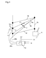
- FIG. 1 shows a schematic section of a conventional tripod with a parallelogram carrier 5a-5d and one according to the invention length-adjustable diagonal strut 6.
- the diagonal strut 6 stiffens the Parallelogram carrier 5a-5d by moving it from the carrier 5a into the bearing between the beams 5b and 5c - biased by a motor 11 - presses.
- she has a spindle 17 in the lower area, which in a thread 12 one Joint bearing 10 is rotatably mounted on the support bracket 5a.
- a double arrow 21 indicates the axial force or displacement of the diagonal strut 6.
- the weight of a microscope 8 is thus determined by the diagonal strut 6 stiffen - parallelogram 5a-5d added.
- such a controller 15a can e.g. with a joystick 22 or the like can be combined to be easy to use enable.
- FIG. 2 shows the schematic structure of a stand for an operating microscope 8 with a stand 1, a swivel joint 2 for a tripod arm 3, a swivel joint 4 for the four movable brackets arranged in the manner of a parallelogram 5a-5d and a diagonal strut 6 according to the invention with a brake 7 which in released state allows a vertical movement of the support bracket 5c.
- the vertical support bracket 5a is not movable in the vertical direction. Possibly it is rotatable in camp 4. In the braked state, the lifting or lowering the carrier 5b, 5c and 5d prevented.
- the brake 7 is only shown symbolically simplified. In most Use cases will have electrically controlled brake shoes that Brake parts of the diagonal strut 6 to each other. It can be a certain The effect of friction until the final braking is intended to be one To achieve friction damping. This damping process of course only works that way long, as long as the brake is not in the stiffened state of the parallelogram 5 is dressed. Normally there should be no movement when stiffened occur. In exceptional stress conditions - within the framework of a special embodiment of the invention - nevertheless a damping effect or at least slight - yielding of the diagonal strut 6 in the sense of a Overload safety take effect.
- a balance weight 9 balances the weight of the microscope 8 via a bearing 13 and the support bracket 5b-d.
- the brake 7 thus has no explicit holding function but only a stiffening function and possibly one Vibration damping function for the parallelogram.
- FIG. 3 shows schematically a tripod arm according to FIG. 1, but with a Movement / position detection unit 14, which is connected to the carrier 5b, however, it can also be arranged on the other supports 5c, 5d or 6.
- the Movement / position detection unit 14 is only a symbol in its representation, that also several movement / position detection units or the like could represent.
- the electronic control unit is equipped with a suitable program 15, which, for example, in addition to the inputs 16 of the user through the Movement / position detection unit 14 via a measuring line 19 Information is supplied to control the motor 11 via the control line 20, used.
- the double arrows 21 indicate the extensibility of the diagonal strut 6 within the Parallelogram 5.
- motor driven are structures with any motor drives such as electric, electromotive, hydraulic, pneumatic or the like understand.
- a "double diagonal strut" symbolically a first diagonal strut 6a and a second diagonal strut 6b, which together with the first diagonal strut 6a takes over the support function - shown.
- the two diagonal struts 6a and 6b have different tasks. While the one 6a has the task already described in FIGS. 1 and 3, has the other 6b about the task of the brake 7 according to FIG. 3, so that both are in their Complement effect.
- a symbolically represented joystick 22 allows the brake 7 and of the motor 11 via the control lines 20a and 20b.
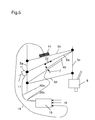
- the structure according to FIG. 5 is also different in that an additional one Movement / position detection unit 14 is provided, which is approximately that above corresponds to specified movement / position detection units 14 and one automatic positioning of the carriers 5b, 5c and 5d allowed, provided that the program in the control is equipped accordingly.
- the control lines 20a and 20b serve to transmit the control information from the controller 15 to the engine 11 and the brake 7.
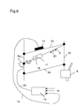
- the structure according to FIG. 6 shows a motor 11, which is a possible variation Spindle 17 rotates, which is mounted in a nut 18 on the diagonal strut and thus one Length variation of the diagonal strut 6 allows.
Landscapes
- Physics & Mathematics (AREA)
- General Physics & Mathematics (AREA)
- Optics & Photonics (AREA)
- Microscoopes, Condenser (AREA)
Abstract
Description
- eine integrierter Federkraft einer Gasdruckfeder ― wie schon oben angegeben- zur (Gewichts-) Kompensation für die Last.
- ein oder mehrere Dämpfungselemente, beispielsweise Gasfedern oder spezielle Gummipuffer mit vorgegebener Feder- und Dämpfungscharakteristik (Schwingungsdämpfung).
- Flüssigkeitsdämpfer.
- Hohe Stabilität bei leichter Bauart.
- Schwingungsarmut trotz leichter Bauart.
- Bei den Varianten mit Antrieb (mit oder ohne Bremse): Vorgebbare und ansteuerbare Neigungswinkel bzw. Vertikalpositionen der optischen Betrachtungseinrichtung.
- Bei den Varianten mit elektronischer Steuerung die Möglichkeit der Kombination mit einem Autofokus-System des Mikroskops.
- Konstruktiv einfache Lösung, nachrüstfähig und wirkungsvoll
- Fig.1
- einen schematischen Ausschnitt aus einem herkömmlichen Stativ mit einem Parallelogrammträger mit erfindungsgemässer längenverstellbarer Diagonalstrebe;
- Fig.2
- einen schematischen Gesamtaufbau eines Stativs mit einem nach Art eines Parallelogramms aufgebauten Stativarm mit gebremster Diagonalstrebe, einem Ausgleichsgewicht und einem Ständer;
- Fig.3
- den Aufbau nach Fig.1 mit längenverstellbarer Diagonalstrebe und einer Bewegungs-/Positions-Erfassungseinheit sowie elektronischer Ansteuerung für den Diagonalstreben-Antrieb;
- Fig.4
- den Aufbau nach Fig.3 mit motorisch angetriebener Diagonalstrebe und einer davon unabhängig wirkenden zweiten Diagonalstrebe mit Bremse zur motorischen Versteifung und Joystickansteuerung für verschiedenste Steuerungsvarianten;
- Fig.5
- eine Variante zum Aufbau gem. Fig.4 mit elektronischer Steuerung und Bewegungs-/Positions-Erfassungseinheit und
- Fig.6
- eine Variante mit einer Spindel innerhalb des Parallelogramms.
- 1
- Ständer bzw. Stativfuss
- 2
- Drehgelenk Stativfuss
- 3
- Stativarm
- 4
- Drehgelenk Stativarm
- 5
- a,b,c,d Nach Art eines Parallelogramms angeordnete bewegliche Halteträger bzw. Träger bzw. Strebe
- 6
- Diagonalstrebe 6a, 6b (Stützelement)
- 7
- Bremse
- 8
- Mikroskop
- 9
- Ausgleichsgewicht
- 10
- Gelenklager
- 11
- Motor
- 12
- Gewinde
- 13
- Lager
- 14
- Bewegungs-/Positions-Erfassungseinheit für Bewegung und/oder Schwingung und/oder Position oder dergleichen
- 15
- Steuerung; 15a Steuerung mit Joystick
- 16
- Input-Signale
- 17
- Spindel
- 18
- Mutter
- 19
- Messleitung
- 20
- a,b, Steuerleitung
- 21
- Doppelpfeil
- 22
- Joystick
Claims (10)
- Vorrichtung zum Halten einer optischen Betrachtungseinrichtung auf einem Stativ (1) mit wenigstens einem Stützelement (6), das Stativteile zueinander abstützt, dadurch gekennzeichnet, dass das Stützelement (6) so angeordnet oder ausgerüstet ist, dass es im Betriebszustand zu einer Überbestimmung von tragenden Stativteilen in einer parallelogrammartigen Trägerkonstruktion kommt.
- Vorrichtung nach Anspruch 1, dadurch gekennzeichnet, dass das Stützelement (6) als Diagonalstrebe ausgebildet und etwa diagonal in einem aus vier zueinander schwenkbaren Trägern (5a-d) bestehenden Tragarm eingesetzt ist.
- Vorrichtung nach Anspruch 1 oder 2, dadurch gekennzeichnet, dass das Stützelement (6) motorisch längenveränderbar ist, wobei für die Längenveränderung wenigstens ein fernsteuerbarer Antrieb vorgesehen ist und der Antrieb außerhalb des Stützelements (6) angeordnet ist und einen Spindeltrieb (17) umfasst.
- Vorrichtung nach einem der vorhergehenden Ansprüche, dadurch gekennzeichnet, dass der Antrieb wenigstens einen Motor (11) aufweist, der elektrisch oder hydraulisch oder pneumatische oder als Federmotor ausgebildet ist.
- Vorrichtung nach einem der vorhergehenden Ansprüche, dadurch gekennzeichnet, dass das Stützelement (6) längenveränderbar und in jeder Längeneinstellung durch eine fernsteuerbare Bremse (7) blockierbar ausgebildet ist.
- Vorrichtung nach einem der vorhergehenden Ansprüche, dadurch gekennzeichnet, dass eine Bewegungs-/Positions-Erfassungseinheit (14) und eine Positions-Speichereinheit vorgesehen sind, die eine wiederholbare Positionierung auf vorgegebene Positionen ermöglicht und die Bewegungs-/Positions-Erfassungseinheit (14) und/oder die Positions-Speichereinheit, wenigstens eine Prozessorsteuerung (15) zur automatischen Steuerung der Verschiebung oder Positionierung umfasst.
- Vorrichtung nach einem der vorhergehenden, dadurch gekennzeichnet, dass das Stützelement (6) mit einem Dämpfungselement und/oder mit einem Bremselement (7) ausgestattet ist.
- Vorrichtung nach einem der vorhergehenden Ansprüche, dadurch gekennzeichnet, dass das Dämpfungselement oder das Bremselement (7) neben einer Diagonalstrebe (6a) angeordnet ist.
- Vorrichtung nach einem der vorhergehenden Ansprüche, dadurch gekennzeichnet, dass sie Bewegungs-, Positions-, Winkel- oder Schwingungssensoren (14) umfasst.
- Vorrichtung nach einem der vorhergehenden Ansprüche, dadurch gekennzeichnet, dass das Stützelement (6) in seinen Anlenkpunkten und relativ zu seinen Antrieben (11) spielfrei gehalten ist.
Applications Claiming Priority (2)
| Application Number | Priority Date | Filing Date | Title |
|---|---|---|---|
| DE10163354A DE10163354A1 (de) | 2001-12-21 | 2001-12-21 | Vorrichtung zum Halten einer optischen Betrachtungseinrichtung |
| DE10163354 | 2001-12-21 |
Publications (3)
| Publication Number | Publication Date |
|---|---|
| EP1324094A2 true EP1324094A2 (de) | 2003-07-02 |
| EP1324094A3 EP1324094A3 (de) | 2004-01-07 |
| EP1324094B1 EP1324094B1 (de) | 2008-03-26 |
Family
ID=7710432
Family Applications (1)
| Application Number | Title | Priority Date | Filing Date |
|---|---|---|---|
| EP02102643A Expired - Lifetime EP1324094B1 (de) | 2001-12-21 | 2002-11-26 | Stativ mit Operationsmikroskop |
Country Status (4)
| Country | Link |
|---|---|
| US (1) | US7158292B2 (de) |
| EP (1) | EP1324094B1 (de) |
| JP (1) | JP4394344B2 (de) |
| DE (2) | DE10163354A1 (de) |
Cited By (2)
| Publication number | Priority date | Publication date | Assignee | Title |
|---|---|---|---|---|
| EP3220038A1 (de) * | 2016-03-17 | 2017-09-20 | Leica Instruments (Singapore) Pte. Ltd. | Verfahren zum ausgleichen einer last mittels eines tragsystem und tragsystem |
| EP3120178B1 (de) * | 2014-03-19 | 2023-08-23 | Leica Microsystems Schweiz AG | Operationsmikroskop-stativ |
Families Citing this family (14)
| Publication number | Priority date | Publication date | Assignee | Title |
|---|---|---|---|---|
| JP3788438B2 (ja) | 2003-03-24 | 2006-06-21 | ソニー株式会社 | 情報記録媒体、情報処理装置、および情報処理方法、並びにコンピュータ・プログラム |
| DE102004063606B4 (de) * | 2004-02-20 | 2015-10-22 | Carl Zeiss Meditec Ag | Haltevorrichtung, insbesondere für ein medizinisch-optisches Instrument, mit einer Einrichtung zur aktiven Schwingungsdämpfung |
| JP4488292B2 (ja) * | 2004-03-03 | 2010-06-23 | オリンパス株式会社 | 手術用顕微鏡 |
| DE102004017971A1 (de) * | 2004-04-12 | 2005-10-27 | Leica Microsystems (Schweiz) Ag | Stativ, insbesondere für Operationsmikroskope, mit einem Kraftspeicherelement |
| CN101287945B (zh) * | 2005-04-15 | 2012-01-25 | 加勒特·W·布朗 | 平衡支撑装置 |
| DE102007034286A1 (de) * | 2007-07-20 | 2009-01-22 | Carl Zeiss Surgical Gmbh | Stativanordnung und Stativ für ein medizinisch-optisches Instrument |
| CA2613838A1 (en) * | 2007-12-07 | 2009-06-07 | Galt Display Rack Co. Ltd. | Carpet display rack |
| DE102010010133A1 (de) * | 2010-03-04 | 2011-09-08 | Leica Microsystems (Schweiz) Ag | Stativ für ein Mikroskop, insbesondere für ein Operationsmikroskop |
| US9458961B2 (en) | 2014-06-10 | 2016-10-04 | Eric Talbot | Equipoise armature |
| US9939603B2 (en) | 2015-09-22 | 2018-04-10 | Novartis Ag | Brake system |
| KR102166495B1 (ko) * | 2019-05-27 | 2020-10-15 | 김은근 | 델타봇 타입의 전동 현미경 스테이지 |
| DE102019208287B4 (de) * | 2019-06-06 | 2023-04-20 | Carl Zeiss Meditec Ag | Verfahren zum Betreiben eines Operationsmikroskopiesystems sowie Operationsmikroskopiesystem |
| CN113093357B (zh) * | 2021-04-20 | 2022-04-26 | 中国科学院长春光学精密机械与物理研究所 | 一种用于航空相机的快速补偿镜对准方法 |
| JP2026508495A (ja) * | 2023-03-02 | 2026-03-11 | アルコン インコーポレイティド | 眼科手術に最適化されたキネマティクスを有する視覚化ロボット |
Family Cites Families (24)
| Publication number | Priority date | Publication date | Assignee | Title |
|---|---|---|---|---|
| US2656058A (en) * | 1948-04-10 | 1953-10-20 | Elmer W Baumann | Truck loading and unloading mechanism |
| US3679154A (en) * | 1970-07-21 | 1972-07-25 | Hughes Tool Co | Heavy lift helicopter with vertically adjustable cockpit |
| DE3173714D1 (en) * | 1980-09-18 | 1986-03-20 | Zeiss Carl Fa | Adjustable stand for optical observing units |
| DE8024962U1 (de) * | 1980-09-18 | 1982-06-09 | Fa. Carl Zeiss, 7920 Heidenheim | Verstellbares stativ fuer optische beobachtungsgeraete |
| JPS63187110U (de) * | 1987-05-18 | 1988-11-30 | ||
| FI872875A7 (fi) * | 1987-06-30 | 1988-12-31 | Siilin Metalli Ky | Anordning foer stoedande av hand. |
| US4852842A (en) * | 1987-09-24 | 1989-08-01 | Lucasey Manufacturing Company, Inc. | Appliance support apparatus |
| JPH02136211U (de) * | 1989-04-19 | 1990-11-14 | ||
| DE3921857A1 (de) * | 1989-07-04 | 1991-01-17 | Wild Leitz Ag | Mit zusatzvorrichtungen ausgestattetes stativ fuer die halterung eines frei positionierbaren geraetes |
| JP3040806B2 (ja) * | 1990-10-03 | 2000-05-15 | 株式会社トプコン | 顕微鏡装置 |
| US5288043A (en) * | 1992-09-11 | 1994-02-22 | Tigliev George S | Balanced suspension system for surgical microscope |
| EP0592703B1 (de) * | 1992-10-12 | 1995-09-27 | Siemens Aktiengesellschaft | Parallelogrammtragarm mit Federgewichtsausgleich |
| DE59208503D1 (de) * | 1992-10-12 | 1997-06-19 | Siemens Ag | Vorrichtung zum Verstellen eines zahnärztlichen Gerätes |
| JPH06258580A (ja) * | 1993-03-03 | 1994-09-16 | Olympus Optical Co Ltd | 手術用顕微鏡支持装置 |
| DE4334069A1 (de) * | 1993-06-21 | 1995-04-13 | Zeiss Carl Fa | Ausbalancierbares Stativ |
| JPH08506560A (ja) * | 1993-08-10 | 1996-07-16 | アッカーマン インター リミテッド | 水平持上げ装置 |
| US5484127A (en) * | 1994-07-15 | 1996-01-16 | Lifetime Products, Inc. | Angled support brace |
| JPH10122481A (ja) * | 1996-08-29 | 1998-05-15 | Sanshiyuuzen Kogyo Kk | 立体画像撮影装置 |
| DE19711572B4 (de) | 1997-03-20 | 2006-09-07 | Carl Zeiss | Operationsmikroskopstativ |
| EP0922181B1 (de) | 1997-06-30 | 2005-03-16 | Leica Microsystems (Schweiz) AG | Stativgewichtsausgleich |
| US6038986A (en) * | 1998-12-17 | 2000-03-21 | Weber Knapp Company | Brake operational control |
| JP2001046399A (ja) * | 1999-08-13 | 2001-02-20 | Olympus Optical Co Ltd | 手術用顕微鏡装置 |
| FI111047B (fi) * | 1999-12-01 | 2003-05-30 | Instrumentarium Corp | Nivelvarsijärjestely erilaisten lääketieteellisten kuvauslaitteiden liittämiseksi nivelletysti tukirakenteisiin |
| US6628457B2 (en) * | 2000-07-11 | 2003-09-30 | Asahi Kogaku Kogyo Kabushiki Kaisha | Antivibration microscope |
-
2001
- 2001-12-21 DE DE10163354A patent/DE10163354A1/de not_active Withdrawn
-
2002
- 2002-11-26 DE DE50211958T patent/DE50211958D1/de not_active Expired - Lifetime
- 2002-11-26 EP EP02102643A patent/EP1324094B1/de not_active Expired - Lifetime
- 2002-12-18 US US10/322,992 patent/US7158292B2/en not_active Expired - Fee Related
- 2002-12-24 JP JP2002372776A patent/JP4394344B2/ja not_active Expired - Fee Related
Cited By (3)
| Publication number | Priority date | Publication date | Assignee | Title |
|---|---|---|---|---|
| EP3120178B1 (de) * | 2014-03-19 | 2023-08-23 | Leica Microsystems Schweiz AG | Operationsmikroskop-stativ |
| EP3220038A1 (de) * | 2016-03-17 | 2017-09-20 | Leica Instruments (Singapore) Pte. Ltd. | Verfahren zum ausgleichen einer last mittels eines tragsystem und tragsystem |
| WO2017160224A1 (en) * | 2016-03-17 | 2017-09-21 | Leica Instruments (Singapore) Pte Ltd | Method of balancing a load using a support system and support system |
Also Published As
| Publication number | Publication date |
|---|---|
| US7158292B2 (en) | 2007-01-02 |
| EP1324094A3 (de) | 2004-01-07 |
| JP4394344B2 (ja) | 2010-01-06 |
| US20030117703A1 (en) | 2003-06-26 |
| DE50211958D1 (de) | 2008-05-08 |
| JP2003215465A (ja) | 2003-07-30 |
| DE10163354A1 (de) | 2003-07-03 |
| EP1324094B1 (de) | 2008-03-26 |
Similar Documents
| Publication | Publication Date | Title |
|---|---|---|
| EP1324094A2 (de) | Vorrichtung zum Halten einer optischen Betrachtungseinrichtung | |
| EP0433426B1 (de) | Mit zusatzvorrichtungen ausgestattetes stativ für die halterung eines frei positionierbaren gerätes | |
| EP1152182B1 (de) | Stativ mit einem Operationsmikroskop | |
| DE69514739T2 (de) | Chirurgische Mikroskop-Einheit | |
| DE3728527A1 (de) | Neigungseinrichtung fuer chirurgische mikroskope | |
| EP2962673A1 (de) | Operationstischsäule für einen operationstisch | |
| DE10350531A1 (de) | Verfahren zur Steuerung eines Tisches und Tischsystem | |
| WO2016074787A1 (de) | Abstützgelenk für einen tragarm einer medizintechnischen stativvorrichtung | |
| DE102015107483A1 (de) | Kamerastabilisierungsvorrichtung und Kamerahalterungsvorrichtung hierfür | |
| CH685038A5 (de) | Dreidimensional verstellbare Deckenaufhängung für Operationsmikroskope. | |
| WO2014023779A1 (de) | Vorrichtung zur stabilisierten führung einer bildaufnahmeeinrichtung | |
| EP1251380A2 (de) | Stativ, insbesondere für ein Operationsmikroskop | |
| DE102013219415B4 (de) | Stativ mit Einrichtung zur Verformungskompensation | |
| EP1101139B1 (de) | Operationsmikroskop-stativ für x-y-verschiebung | |
| EP1310727B1 (de) | Operations-Mikroskop | |
| DE102011119814A1 (de) | Stativ | |
| EP3120178B1 (de) | Operationsmikroskop-stativ | |
| WO2000077589A1 (de) | Vorrichtung zum steuern einer einrichtung | |
| WO2014005583A1 (de) | Manipulator mit serieller und paralleler kinematik | |
| DE102013206696B4 (de) | Vorrichtung und ein Verfahren zur Steuerung einer Handhabungseinrichtung | |
| CH685653A5 (de) | Stativ mit einer mechanischen Steuereinheit für ein damit verbundenes Operationsmikroskop. | |
| DE10314156B9 (de) | Schwenkhalterungsanordnung und Verfahren zum Steuern einer solchen | |
| DE4316037C2 (de) | Adapter zum Positionieren eines an einem Stativ angeordneten medizinischen Therapie- und/oder Diagnose-Instrumentes und Stativ mit Adapter | |
| WO2002016820A1 (de) | Kamerastativkopf | |
| DE4426160A1 (de) | Lagerung für ein um mindestens eine Achse bewegliches Bauteil |
Legal Events
| Date | Code | Title | Description |
|---|---|---|---|
| PUAI | Public reference made under article 153(3) epc to a published international application that has entered the european phase |
Free format text: ORIGINAL CODE: 0009012 |
|
| AK | Designated contracting states |
Designated state(s): AT BE BG CH CY CZ DE DK EE ES FI FR GB GR IE IT LI LU MC NL PT SE SK TR |
|
| AX | Request for extension of the european patent |
Extension state: AL LT LV MK RO SI |
|
| PUAL | Search report despatched |
Free format text: ORIGINAL CODE: 0009013 |
|
| AK | Designated contracting states |
Kind code of ref document: A3 Designated state(s): AT BE BG CH CY CZ DE DK EE ES FI FR GB GR IE IT LI LU MC NL PT SE SK TR |
|
| AX | Request for extension of the european patent |
Extension state: AL LT LV MK RO SI |
|
| RIC1 | Information provided on ipc code assigned before grant |
Ipc: 7F 16M 11/04 B Ipc: 7G 02B 21/00 A Ipc: 7G 02B 7/00 B Ipc: 7G 02B 23/16 B |
|
| 17P | Request for examination filed |
Effective date: 20040707 |
|
| 17Q | First examination report despatched |
Effective date: 20040817 |
|
| AKX | Designation fees paid |
Designated state(s): CH DE FR GB LI |
|
| GRAP | Despatch of communication of intention to grant a patent |
Free format text: ORIGINAL CODE: EPIDOSNIGR1 |
|
| RTI1 | Title (correction) |
Free format text: SUPPORT WITH A SURGICAL MICROSCOPE |
|
| GRAS | Grant fee paid |
Free format text: ORIGINAL CODE: EPIDOSNIGR3 |
|
| GRAA | (expected) grant |
Free format text: ORIGINAL CODE: 0009210 |
|
| AK | Designated contracting states |
Kind code of ref document: B1 Designated state(s): CH DE FR GB LI |
|
| REG | Reference to a national code |
Ref country code: GB Ref legal event code: FG4D Free format text: NOT ENGLISH |
|
| REG | Reference to a national code |
Ref country code: CH Ref legal event code: EP |
|
| REF | Corresponds to: |
Ref document number: 50211958 Country of ref document: DE Date of ref document: 20080508 Kind code of ref document: P |
|
| EN | Fr: translation not filed | ||
| PLBE | No opposition filed within time limit |
Free format text: ORIGINAL CODE: 0009261 |
|
| STAA | Information on the status of an ep patent application or granted ep patent |
Free format text: STATUS: NO OPPOSITION FILED WITHIN TIME LIMIT |
|
| 26N | No opposition filed |
Effective date: 20081230 |
|
| PG25 | Lapsed in a contracting state [announced via postgrant information from national office to epo] |
Ref country code: FR Free format text: LAPSE BECAUSE OF FAILURE TO SUBMIT A TRANSLATION OF THE DESCRIPTION OR TO PAY THE FEE WITHIN THE PRESCRIBED TIME-LIMIT Effective date: 20090116 |
|
| REG | Reference to a national code |
Ref country code: CH Ref legal event code: PL |
|
| GBPC | Gb: european patent ceased through non-payment of renewal fee |
Effective date: 20081126 |
|
| PG25 | Lapsed in a contracting state [announced via postgrant information from national office to epo] |
Ref country code: LI Free format text: LAPSE BECAUSE OF NON-PAYMENT OF DUE FEES Effective date: 20081130 Ref country code: CH Free format text: LAPSE BECAUSE OF NON-PAYMENT OF DUE FEES Effective date: 20081130 |
|
| PG25 | Lapsed in a contracting state [announced via postgrant information from national office to epo] |
Ref country code: GB Free format text: LAPSE BECAUSE OF NON-PAYMENT OF DUE FEES Effective date: 20081126 |
|
| PGFP | Annual fee paid to national office [announced via postgrant information from national office to epo] |
Ref country code: DE Payment date: 20151211 Year of fee payment: 14 |
|
| REG | Reference to a national code |
Ref country code: DE Ref legal event code: R119 Ref document number: 50211958 Country of ref document: DE |
|
| PG25 | Lapsed in a contracting state [announced via postgrant information from national office to epo] |
Ref country code: DE Free format text: LAPSE BECAUSE OF NON-PAYMENT OF DUE FEES Effective date: 20170601 |