EP1325534B1 - Antennenplattform - Google Patents
Antennenplattform Download PDFInfo
- Publication number
- EP1325534B1 EP1325534B1 EP01979070A EP01979070A EP1325534B1 EP 1325534 B1 EP1325534 B1 EP 1325534B1 EP 01979070 A EP01979070 A EP 01979070A EP 01979070 A EP01979070 A EP 01979070A EP 1325534 B1 EP1325534 B1 EP 1325534B1
- Authority
- EP
- European Patent Office
- Prior art keywords
- platform
- elements
- supporting means
- equipment
- room
- Prior art date
- Legal status (The legal status is an assumption and is not a legal conclusion. Google has not performed a legal analysis and makes no representation as to the accuracy of the status listed.)
- Expired - Lifetime
Links
- 238000010276 construction Methods 0.000 claims abstract description 16
- 239000000463 material Substances 0.000 claims abstract description 10
- 230000008878 coupling Effects 0.000 claims description 12
- 238000010168 coupling process Methods 0.000 claims description 12
- 238000005859 coupling reaction Methods 0.000 claims description 12
- 238000004378 air conditioning Methods 0.000 claims description 4
- 230000002411 adverse Effects 0.000 claims description 2
- 239000000969 carrier Substances 0.000 description 3
- 229910000831 Steel Inorganic materials 0.000 description 2
- 238000012423 maintenance Methods 0.000 description 2
- 238000000034 method Methods 0.000 description 2
- 239000010959 steel Substances 0.000 description 2
- 230000005540 biological transmission Effects 0.000 description 1
- 230000015572 biosynthetic process Effects 0.000 description 1
- 230000000694 effects Effects 0.000 description 1
- 230000002349 favourable effect Effects 0.000 description 1
- 239000002184 metal Substances 0.000 description 1
- 231100000989 no adverse effect Toxicity 0.000 description 1
- 229920000515 polycarbonate Polymers 0.000 description 1
- 239000004417 polycarbonate Substances 0.000 description 1
- 230000005855 radiation Effects 0.000 description 1
- 239000007787 solid Substances 0.000 description 1
- 239000002023 wood Substances 0.000 description 1
Images


Classifications
-
- E—FIXED CONSTRUCTIONS
- E04—BUILDING
- E04H—BUILDINGS OR LIKE STRUCTURES FOR PARTICULAR PURPOSES; SWIMMING OR SPLASH BATHS OR POOLS; MASTS; FENCING; TENTS OR CANOPIES, IN GENERAL
- E04H12/00—Towers; Masts or poles; Chimney stacks; Water-towers; Methods of erecting such structures
- E04H12/22—Sockets or holders for poles or posts
- E04H12/2238—Sockets or holders for poles or posts to be placed on the ground
-
- H—ELECTRICITY
- H01—ELECTRIC ELEMENTS
- H01Q—ANTENNAS, i.e. RADIO AERIALS
- H01Q1/00—Details of, or arrangements associated with, antennas
- H01Q1/005—Damping of vibrations; Means for reducing wind-induced forces
-
- H—ELECTRICITY
- H01—ELECTRIC ELEMENTS
- H01Q—ANTENNAS, i.e. RADIO AERIALS
- H01Q1/00—Details of, or arrangements associated with, antennas
- H01Q1/12—Supports; Mounting means
- H01Q1/1207—Supports; Mounting means for fastening a rigid aerial element
-
- H—ELECTRICITY
- H01—ELECTRIC ELEMENTS
- H01Q—ANTENNAS, i.e. RADIO AERIALS
- H01Q1/00—Details of, or arrangements associated with, antennas
- H01Q1/12—Supports; Mounting means
- H01Q1/1242—Rigid masts specially adapted for supporting an aerial
Definitions
- the present invention relates to a platform, comprising a bearing part and coupled thereto means for connecting an antenna mast or the like to the bearing part.
- antenna masts especially for the so-called GSM base stations, as well as for UMTS base stations and the like, on high objects such as roofs of buildings.
- the antenna masts are mounted on flat roofs of flat buildings and the like.
- the antenna's mounting point at a height of 30 metres.
- the antennae themselves are mounted on one or more masts having a height of approximately 5 metres, positioned on the roof.
- this equipment cabinet is connected with the antennae, of which there are usually three.
- the equipment cabinet is then connected to a power supply and is linked with the permanent network by means of a cable connection or by means of beam transmission.
- the known antenna platforms have a great number of drawbacks, in particular with respect to their fastening to the mounting face.
- the known antenna platforms are fastened by means of a mechanical coupling to the supporting construction of the building underneath. If the concrete roofs are sufficiently strong, the outer layer of roof-covering is cut open and an anchor is provided in the concrete for mounting an individual base made of wood or steel. In order to fix said anchors, holes are drilled into the concrete, in which they are lodged. The individual base is slid over said anchors and is fixed. The individual bases are subsequently finished to be water-tight. The platform is then mounted on the individual base.
- the roof itself has insufficient bearing power, for example, in the case of wooden or steel roofs
- the underlying supporting construction of trusses is used for fastening the platform. To this end a hole is made above a truss through the entire roof construction.
- the individual base is then mounted on the truss. Finally the individual base is finished to be water-tight, which has to be done very precisely.
- the elements consist of elongated elements.
- the supports consist of longitudinal beams and cross beams, providing a simple modular system, allowing simple extensions to be carried out to the platform at the place of destination.
- the system according to the invention is very advantageous especially when the platform is to be placed on a flat roof of a high building.
- the separate modular parts may be taken to the place of destination, to subsequently be assembled there.
- the platform may be assembled in an assembly room and be placed directly on to the roof or the like. In accordance with the invention, it is not necessary to anchor the construction to the building.
- the supporting means are adjustable in height, it is simple to level out possible unevennesses in the mounting face.
- the vibration-isolating construction of the supporting means wherein said construction may consist, for example, of a vibration-isolating material such as a rubber-like material, provides a number of advantages. It has a high friction coefficient, which minimizes any movement of the platform over the mounting face. Such material is relatively soft so that damage to the mounting face is prevented. It is also vibration-isolating. Finally, such material has a low thermal conduction coefficient so that thermal bridges to the mounting face are avoided.
- a vibration-isolating material such as a rubber-like material
- Embodying the supporting means with a solid core, for example, metal provides a good load distribution over a larger area; maximally as large as the surface area of the supporting means themselves.
- the elements are preferably provided with a plurality of fastening points for the supporting means in order to allow them to be fastened to the platform at different positions. This means that they can be positioned, for example, exactly above roof trusses. This allows the supporting means, moreover, to be attached under the platform such that they do not rest on elements mounted on the roof such as chimneys and the like.
- the elements comprise fastening positions for supporting means in such numbers that the strength and soundness of the elements are not adversely affected.
- the elements comprise at least two, preferably at least three, and more preferably at least four fastening positions for the supporting means.
- a further preferred embodiment provides in the supporting means being pivotingly fastened to the platform.
- the platform may also be provided with connecting means for fastening equipment cabinets that house this system equipment thereto.
- the room comprises an air conditioning system and is equipped to accommodate equipment to be used with an antenna system.
- the air conditioning system may comprise a traditional air conditioner or a (mechanical) air circulation system and/or a heater and the like.
- the room may comprise a standard fastening whereby different kinds of equipment (cabinets) may be fastened in the room by means of adapters.
- cabinets different kinds of equipment
- the room comprises means to allow a top section to be mounted on top.
- the top section preferably comprises a niche which, when the top section is mounted on the equipment room, lies in the extended direction of the niche that is provided in the wall of the equipment room.
- the known GSM/UMTS antennae can be placed in such a niche. It is, for example, possible to place a beam transmitter, preferably of the kind known in the art, in the top section. This may then be protected from the surroundings by a material such as polycarbonate, which is substantially permeable with regard to the respective radiation.
- the elements are provided with grids suitable to be walked over. In that case there will be no direct contact with the roof surface during possible maintenance activities. It is also possible to provide fencing around the periphery of the platform. This is especially advantageous if the antenna platform is mounted on a high building.
- Figure 1 shows a side view of an antenna platform and mounted thereon a mast with antenna.
- Figure 2 shows a top view of the embodiment according to Figure 1.
- Figure 3 shows the side view of another embodiment of the invention.
- Figure 4 shows a top view of the embodiment of Figure 3.
- Figure 5 shows a schematic illustration of an equipment cabinet mounted on the platform according to the invention.
- Figure 6 shows a top view of a portion of the bearing part of the platform.
- Figure 7 shows the top view of a cross beam with two supporting means coupled thereto.
- Figures 8A and 8B show a side view of the construction according to Figure 7.
- Figure 9 shows a top view of a room according to the invention.
- the antenna platform 1 comprises a bearing surface 2, formed substantially by the carriers 3. Also provided are means 4 on which an antenna mast 5 can be mounted.
- the carriers are comprised of elongated elements 3, being at their end 6, which in the present case faces toward a centre, coupled to means 4 on which the antenna mast 5 is mounted.
- the outward facing ends 7 of the elongated elements 3 are connected to supporting means 8, fastened with the aid of cross beams 9.
- the means 4 consists of a central part to which a mast 5 can be coupled. Coupling may occur in any suitable manner.
- ends 6 of the elongated elements 3 may be interconnected, after which the means 4 are coupled thereto individually. It is also possible to couple the ends 6 of the elongated elements 3 directly to the means 4.
- the supporting means 8 have a relatively large surface area. In this way the load per unit of area on the mounting face is still low despite the fact that the weight of the entire antenna platform 1 plus mast and antennas may be considerable. This allows the antenna platform 1 to be mounted also on a mounting face with a limited strength, e.g. a flat roof of a building.
- FIG 3 shows another embodiment of an antenna platform 1 according to the invention.
- the carriers are comprised substantially of elongated elements 3 placed horizontally, coupled to supporting means 8 with the aid of coupling means (not shown). According to a preferred embodiment, these may be mounted anywhere on the elements.
- a mast 5 is mounted, which is fastened with the aid of struts 10 (in Figure 3 only one strut 10 is shown).
- the mast is connected to the bearing surface 2 by means of coupling means (not shown).
- the mast is provided with antennae 11.
- the platform is also provided with fencing 12. This fencing ensures that persons who are on the platform for maintenance, repair and the like, will not step outside the platform area. This is especially important when an antenna platform 1, as shown in the figure, is mounted on a high surface.
- FIG 4 shows a top view of an antenna platform 1 as illustrated in Figure 3.
- the various elongated elements 3 that are interconnected can be clearly distinguished.
- the elements 3 form elongated beams and cross beams that are preferably interchangeable and may have the same shape.
- the supporting means 8 can also be clearly seen.
- the fencing 12 is connected with the elongated elements 3.
- the fencing 12 there is also a provision 14 that is comprised of, for example, a pivoting element such as a door 14 via which one can simply come inside of the fencing on the antenna platform 1. In that case it is advantageous to place, for example, grids (not shown) on the antenna platform, supported by the elongated elements 3.
- the grids generally used in the art are provided with large openings so that rainwater and dirt will fall through the grids.
- the mast 5 is mounted on the elongated elements 3 with the aid of the coupling means 4, which may simply be comprised of a flange or the like. It is common practice in the art to mount a mast on a mounting face with the aid of coupling means.
- FIG 5 shows a schematic side view of an antenna platform 1 according to the invention, depicting only elongated elements 3 and supporting means 8.
- the supporting means 8 are coupled to the elongated elements 3 by means of coupling means 19.
- the height of the supporting means 8 is adjustable by means of, for example, adjusting screws 15. This makes it possible to position the antenna platform 1 substantially horizontally even if the mounting face 16 is not entirely horizontal or flat.
- This Figure 5 also shows an equipment cabinet 17 comprising system equipment for cooperating with the antennae.
- suitable coupling means 18 preferably using an adapter (not shown)
- the cabinet 17 may be mounted on the antenna platform 1, in particular on the elongated elements 3. of course, it is also possible to use an adapter whose one side is suitable for fastening to the elongated elements 3, and whose other side is suitable for fastening to the equipment cabinet 17.
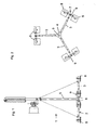
- Figure 6 shows a top view of a portion of the bearing part of the platform 1 according to the invention.
- the supporting means 8 are fastened in pairs to an intermediate beam or cross beam 9.
- Said cross beam 9 is fastened to an element 3 via a hinging mechanism 20.
- Figure 7 shows a top view of a cross beam 9 and two supporting means 8 fastened thereto, as shown in Figure 6.
- Figure 8A shows a side view of the cross beam 9 according to Figure 7 in the direction of the arrows 8A-8A, also clearly showing the hinge mechanism 20.
- the supporting means 8 When placing the platform on a mounting face, the supporting means 8 will be able to adapt to the shape of the mounting face.
- the hinge mechanism may be fixed by means of bolt connections 21. Thereby guaranteeing a stable positioning of the platform on the mounting face.
- Figure 8B shows a side view in the direction of the arrows 8B-8B according to Figures 7 and 8A.
- the supporting means 8 are connected to the cross beam 9 by coupling means 19, and are adjustable in height by means of adjusting screws 15.
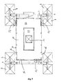
- Figure 9 shows a top view of an equipment room 21, in which the necessary equipment cabinets as described above and as known in the art, may be located.
- the room 21 is located on a platform 1 according to the invention.
- a removable plate 23 On the roof 22 of the room 21 an opening is provided covered with a removable plate 23.
- This plate may be replaced by a top section which, for example, houses an emergency power supply or a beam transmitter or possibly the said GSM/UMTS transmitters.
- the top side of the top section may be covered, for example, with the said removable cover plate 23.
- the cover plate 23 may optionally be provided with a man hole, which may be covered by a plate 24.
- the room 21 may be provided with adapters to allow any desirable equipment cabinet known in the art to be fastened therein.
- the room 21 may be provided with one or more niches 26.
- the fastening means for GSM/UMTS antennae 27 may be placed, or both the fastening means and the antennae.
- the niches are preferably also provided with means for putting cables through to allow the cables connecting the antennae with the equipment in the room to be put through into the equipment room.
- the elements 3 may comprise a large number of fastening points for supporting means 8. The number of fastening points may maximally be such as to produce no adverse effect on the necessary strength of the elements 3.
- a result very conveniently achieved with the antenna platform according to the invention is that there is no need for permanent connection between the bearing construction for an antenna mast and the remaining equipment cabinets, so that no break work in the roof construction of a building is required. This allows the mounting of an antenna platform to be carried out much more quickly. It is also possible to mount an antenna platform on a building in rainy weather conditions.
- the invention is not limited to the foregoing description. It is, for example, possible to mount the antenna platform on a mounting face that is not flat. A platform as shown in Figures 3 and 4 may possibly also be embodied without fencing. It is also possible that the supporting means 8 have another form than the square shapes shown in the figures. Depending on the size of the antenna platform and the strength of the mounting face, the number of supporting means may possibly be increased or reduced in relation to the number of supporting means shown in the figures.
Landscapes
- Engineering & Computer Science (AREA)
- Architecture (AREA)
- Civil Engineering (AREA)
- Structural Engineering (AREA)
- Support Of Aerials (AREA)
- Details Of Aerials (AREA)
- Axle Suspensions And Sidecars For Cycles (AREA)
- Building Environments (AREA)
Claims (16)
- Eine Plattform, die ein tragendes Teil und damit gekoppelt eine Einrichtung zum Verbinden eines Antennenmastes mit dem tragenden Teil, damit zu verwendende Geräte oder dergleichen umfasst, wobei das tragende Teil aus im Wesentlichen ähnlichen, gegeneinander austauschbaren und miteinander verbundenen Elementen (3) besteht; wobei die Plattform (1) eine Trägereinrichtung (8) umfasst, die die Plattform (1) auf einer Anbringfläche (16) trägt, ohne mit derselben verbunden zu sein; und wobei die Trägereinrichtung (8) höhenverstellbar ist, dadurch gekennzeichnet, dass an der der Anbringfläche zugewandten Seite die Trägereinrichtung (8) eine Schwingungsisolierungskonstruktion umfasst, beispielsweise ein Schwingungsisolierungsmaterial wie z.B. ein gummiartiges Material; und dadurch, dass die Elemente (3) eine Mehrzahl von Befestigungspunkten für die Trägereinrichtung (8) umfassen.
- Eine Plattform gemäß Anspruch 1, dadurch gekennzeichnet, dass die Elemente (3) längliche Elemente sind.
- Eine Plattform gemäß Anspruch 1 oder 2, dadurch gekennzeichnet, dass die Elemente (3) Längsbalken und Querbalken umfassen.
- Eine Plattform gemäß einem der vorhergehenden Ansprüche, dadurch gekennzeichnet, dass mehrere Elemente (3) in der verlängerten Richtung eines jeweils anderen Elements verbunden sind.
- Eine Plattform gemäß einem der vorhergehenden Ansprüche, dadurch gekennzeichnet, dass die Elemente (3) zumindest zwei, vorzugsweise zumindest drei und stärker bevorzugt zumindest vier Befestigungspositionen für die Trägereinrichtung (8) umfassen.
- Eine Plattform gemäß einem der vorhergehenden Ansprüche, dadurch gekennzeichnet, dass die Elemente (3) Befestigungspositionen für Trägereinrichtungen (8) in einer derartigen Anzahl umfassen, dass die Stärke und Brauchbarkeit der Elemente (3) nicht negativ beeinflusst ist.
- Eine Plattform gemäß einem der vorhergehenden Ansprüche, dadurch gekennzeichnet, dass die Trägereinrichtung (8) auf schwenkbare Weise an der Plattform befestigt ist.
- Eine Plattform gemäß einem der vorhergehenden Ansprüche, dadurch gekennzeichnet, dass die Anbringfläche (16) durch ein im Wesentlichen flaches Dach gebildet ist.
- Eine Plattform gemäß einem der vorhergehenden Ansprüche, dadurch gekennzeichnet, dass um die Peripherie der Plattform (2) herum eine Einzäunung vorgesehen ist.
- Eine Plattform gemäß einem der vorhergehenden Ansprüche, dadurch gekennzeichnet, dass dieselbe mit einer mit derselben gekoppelten Einrichtung zum Verbinden eines Geräteraums versehen ist, wobei der Raum ein Klimatisierungssystem umfasst und dahin gehend ausgestattet ist, Geräte zu beherbergen, die mit einem Antennensystem, insbesondere mit einem GSM/UMTS-Antennensystem, verwendet werden sollen.
- Eine Kombination eines Geräteraums und einer Plattform gemäß einem der Ansprüche 1 bis 10, insbesondere mit einem GSM/UMTS-Antennensystem, dadurch gekennzeichnet, dass der Raum ein Klimatisierungssystem umfasst und dahin gehend ausgestattet ist, Geräte zu beherbergen, die mit einem Antennensystem verwendet werden sollen.
- Eine Kombination gemäß Anspruch 11, dadurch gekennzeichnet, dass in der Außenwand des Raums eine Nische zum Beherbergen einer Antenne vorgesehen ist.
- Eine Kombination gemäß Anspruch 11 oder 12, dadurch gekennzeichnet, dass die Nische mit einer Einrichtung zum Durchlegen von Kabeln versehen ist, um in der Lage zu sein, die Antenne mit den Geräten in dem Geräteraum zu verbinden.
- Eine Kombination gemäß einem der Ansprüche 11 bis 13, dadurch gekennzeichnet, dass der Geräteraum eine Kopplungseinrichtung umfasst, um zu ermöglichen, dass ein oberer Abschnitt an dem Raum angebracht wird.
- Eine Kombination gemäß Anspruch 14, dadurch gekennzeichnet, dass der obere Abschnitt eine Nische umfasst, die, wenn der obere Abschnitt an dem Geräteraum angebracht ist, in der verlängerten Richtung der Nische liegt, die in der Wand des Geräteraums vorgesehen ist.
- Eine Kombination gemäß einem der Ansprüche 11 bis 15, dadurch gekennzeichnet, dass die Nische durch ein Material abgedeckt ist, das in Bezug auf Funkwellen im Wesentlichen durchlässig ist.
Applications Claiming Priority (3)
| Application Number | Priority Date | Filing Date | Title |
|---|---|---|---|
| NL1016191 | 2000-09-15 | ||
| NL1016191A NL1016191C2 (nl) | 2000-09-15 | 2000-09-15 | Antenneplatform. |
| PCT/NL2001/000687 WO2002031910A1 (en) | 2000-09-15 | 2001-09-14 | Antenna platform |
Publications (2)
| Publication Number | Publication Date |
|---|---|
| EP1325534A2 EP1325534A2 (de) | 2003-07-09 |
| EP1325534B1 true EP1325534B1 (de) | 2007-01-31 |
Family
ID=19772087
Family Applications (1)
| Application Number | Title | Priority Date | Filing Date |
|---|---|---|---|
| EP01979070A Expired - Lifetime EP1325534B1 (de) | 2000-09-15 | 2001-09-14 | Antennenplattform |
Country Status (6)
| Country | Link |
|---|---|
| EP (1) | EP1325534B1 (de) |
| AT (1) | ATE353166T1 (de) |
| AU (1) | AU2002211059A1 (de) |
| DE (1) | DE60126417D1 (de) |
| NL (1) | NL1016191C2 (de) |
| WO (1) | WO2002031910A1 (de) |
Cited By (3)
| Publication number | Priority date | Publication date | Assignee | Title |
|---|---|---|---|---|
| DE102015005882A1 (de) * | 2015-05-06 | 2016-11-10 | Manfred Tammen | Ballast - Stein |
| RU2651738C1 (ru) * | 2017-06-23 | 2018-04-23 | Общество с ограниченной ответственностью "Унискан" | Мачта со стабилизированной по направлению верхней рабочей площадкой |
| WO2018236244A1 (ru) * | 2017-06-23 | 2018-12-27 | Андрей Андреевич БРЫЗГАЛОВ | Мачта со стабилизированной по направлению верхней рабочей площадкой |
Families Citing this family (12)
| Publication number | Priority date | Publication date | Assignee | Title |
|---|---|---|---|---|
| EP1338728A1 (de) * | 2002-02-25 | 2003-08-27 | Birgit Battel | Tragkonstruktion |
| FR2851637B1 (fr) * | 2003-02-21 | 2005-04-29 | Georges Pascal Morabito | Dispositif modulaire destine a assurer la stabilite d'un objet soumis a des forces horizontales ayant tendance a le renverser (vent par exemple) |
| EP1482591A1 (de) * | 2003-05-28 | 2004-12-01 | Koninklijke KPN N.V. | Verfahren und Anlage um eine Antenne auf dem Dach zu montieren |
| ES2222108B1 (es) * | 2004-04-02 | 2006-03-16 | Pesa Telecom, S.A. | "dispositivo para la transformacion de antenas de transmision de ondas de telefonia y metodo para efectuar dicha transformacion". |
| DE102005023788A1 (de) * | 2005-05-19 | 2006-11-23 | Modular Engineering Gmbh | Mastfuß |
| FR2886660B1 (fr) * | 2005-06-02 | 2007-09-07 | Somep Ind Soc Par Actions Simp | Garde corps relevable et support d'antenne de telecommunications mettant en oeuvre un tel garde corps |
| GB2480169B (en) * | 2009-10-09 | 2014-03-19 | Fasmetrics Ltd | Antenna mast system and mounting apparatus |
| FR2964133B1 (fr) * | 2010-08-24 | 2013-04-26 | Luigi Pillosio | Dispositif de maintien sur une plate forme d'un mat vertical |
| EP2977529A1 (de) * | 2014-07-21 | 2016-01-27 | INTEGERIX Planungsbüro GmbH | Punktfundament |
| SE537782C2 (sv) * | 2014-08-25 | 2015-10-20 | Mafi Ab | Fastsättningsanordning |
| SE541667C2 (sv) | 2016-05-27 | 2019-11-19 | Mafi Ab | Fästanordning med två fästelement och två hylsmuttrar för rörformigt element |
| IL246617B2 (en) | 2016-07-05 | 2023-10-01 | Eyal Brayer | Means and Methods for Free Dome Range |
Family Cites Families (6)
| Publication number | Priority date | Publication date | Assignee | Title |
|---|---|---|---|---|
| US4649675A (en) * | 1985-11-12 | 1987-03-17 | M/A-Com | Nonpenetrating roof mount for antenna |
| US4799642A (en) * | 1987-02-03 | 1989-01-24 | Rt/Katek Communications Group, Inc. | Antenna mounting |
| US4912893A (en) * | 1987-12-21 | 1990-04-03 | Miller Harmon R | Transportable CMR cell site |
| US5184141A (en) * | 1990-04-05 | 1993-02-02 | Vought Aircraft Company | Structurally-embedded electronics assembly |
| US5467955A (en) * | 1994-07-28 | 1995-11-21 | Bellsouth Corporation | Antenna mounting platform for a monopole tower |
| DE29604992U1 (de) * | 1996-03-18 | 1996-09-26 | Becker, Johannes, 86836 Graben | Schirm |
-
2000
- 2000-09-15 NL NL1016191A patent/NL1016191C2/nl not_active IP Right Cessation
-
2001
- 2001-09-14 AU AU2002211059A patent/AU2002211059A1/en not_active Abandoned
- 2001-09-14 EP EP01979070A patent/EP1325534B1/de not_active Expired - Lifetime
- 2001-09-14 AT AT01979070T patent/ATE353166T1/de not_active IP Right Cessation
- 2001-09-14 DE DE60126417T patent/DE60126417D1/de not_active Expired - Lifetime
- 2001-09-14 WO PCT/NL2001/000687 patent/WO2002031910A1/en not_active Ceased
Cited By (4)
| Publication number | Priority date | Publication date | Assignee | Title |
|---|---|---|---|---|
| DE102015005882A1 (de) * | 2015-05-06 | 2016-11-10 | Manfred Tammen | Ballast - Stein |
| DE102015005882B4 (de) * | 2015-05-06 | 2021-01-28 | Manfred Tammen | Ballast - Stein |
| RU2651738C1 (ru) * | 2017-06-23 | 2018-04-23 | Общество с ограниченной ответственностью "Унискан" | Мачта со стабилизированной по направлению верхней рабочей площадкой |
| WO2018236244A1 (ru) * | 2017-06-23 | 2018-12-27 | Андрей Андреевич БРЫЗГАЛОВ | Мачта со стабилизированной по направлению верхней рабочей площадкой |
Also Published As
| Publication number | Publication date |
|---|---|
| ATE353166T1 (de) | 2007-02-15 |
| AU2002211059A1 (en) | 2002-04-22 |
| DE60126417D1 (de) | 2007-03-22 |
| WO2002031910B1 (en) | 2002-09-26 |
| WO2002031910A1 (en) | 2002-04-18 |
| NL1016191C2 (nl) | 2002-03-18 |
| EP1325534A2 (de) | 2003-07-09 |
Similar Documents
| Publication | Publication Date | Title |
|---|---|---|
| US5904004A (en) | Integrated communications equipment enclosure and antenna tower | |
| EP1325534A2 (de) | Antennenplattform | |
| US8950158B2 (en) | Cellular antenna tower and equipment enclosure based on shipping container | |
| US8125403B2 (en) | Tubular telecom tower | |
| US3771273A (en) | Prefabricated building | |
| US6557312B2 (en) | Prefabricated-building tower foundation | |
| US4158941A (en) | Precast building structure and method of assembly | |
| BG100624A (bg) | Противоземетръсен,ветроустойчив,пожароустойчив,полуготов строителен панел и изградени с него конструкции | |
| EP1577462A1 (de) | Freiluftzelt mit seitenwindschutz | |
| US11242680B2 (en) | Building system and method thereof | |
| WO1995032346A1 (en) | Shell-plate construction based on a latticework system and a method for installation of same | |
| JP6034951B2 (ja) | 構造的完全性及び地震耐力を提供する建築システム | |
| US20030142034A1 (en) | Telecommunications mast installation | |
| US6351250B1 (en) | Antenna tower and support apparatus | |
| JPH0586647A (ja) | 建築物 | |
| CA2418021A1 (en) | Method of constructing and erecting a tower | |
| US4171600A (en) | Process for constructing modular building and resulting product | |
| US5720141A (en) | Structure and method for encapsulating an existing building | |
| EP0982793A2 (de) | Antennenmast | |
| KR920701590A (ko) | 조립식 지붕구조물과 그의 조립 및 설치방법 | |
| US20070245639A1 (en) | Circular building structure and method of constructing the same | |
| WO2002056410A2 (en) | Conical communications pole with cavity | |
| RU2107137C1 (ru) | Архитектурно-строительная система из сототермоструктурных объемных модулей для возведения жилых зданий многоугольной формы в плане | |
| RU2823480C1 (ru) | Юрта | |
| CA2423353A1 (en) | Prefabricated building system |
Legal Events
| Date | Code | Title | Description |
|---|---|---|---|
| PUAI | Public reference made under article 153(3) epc to a published international application that has entered the european phase |
Free format text: ORIGINAL CODE: 0009012 |
|
| 17P | Request for examination filed |
Effective date: 20030415 |
|
| AK | Designated contracting states |
Designated state(s): AT BE CH CY DE DK ES FI FR GB GR IE IT LI LU MC NL PT SE TR |
|
| AX | Request for extension of the european patent |
Extension state: AL LT LV MK RO SI |
|
| 17Q | First examination report despatched |
Effective date: 20050303 |
|
| GRAP | Despatch of communication of intention to grant a patent |
Free format text: ORIGINAL CODE: EPIDOSNIGR1 |
|
| GRAS | Grant fee paid |
Free format text: ORIGINAL CODE: EPIDOSNIGR3 |
|
| GRAA | (expected) grant |
Free format text: ORIGINAL CODE: 0009210 |
|
| AK | Designated contracting states |
Kind code of ref document: B1 Designated state(s): AT BE CH CY DE DK ES FI FR GB GR IE IT LI LU MC NL PT SE TR |
|
| PG25 | Lapsed in a contracting state [announced via postgrant information from national office to epo] |
Ref country code: DK Free format text: LAPSE BECAUSE OF FAILURE TO SUBMIT A TRANSLATION OF THE DESCRIPTION OR TO PAY THE FEE WITHIN THE PRESCRIBED TIME-LIMIT Effective date: 20070131 Ref country code: LI Free format text: LAPSE BECAUSE OF FAILURE TO SUBMIT A TRANSLATION OF THE DESCRIPTION OR TO PAY THE FEE WITHIN THE PRESCRIBED TIME-LIMIT Effective date: 20070131 Ref country code: FI Free format text: LAPSE BECAUSE OF FAILURE TO SUBMIT A TRANSLATION OF THE DESCRIPTION OR TO PAY THE FEE WITHIN THE PRESCRIBED TIME-LIMIT Effective date: 20070131 Ref country code: AT Free format text: LAPSE BECAUSE OF FAILURE TO SUBMIT A TRANSLATION OF THE DESCRIPTION OR TO PAY THE FEE WITHIN THE PRESCRIBED TIME-LIMIT Effective date: 20070131 Ref country code: CH Free format text: LAPSE BECAUSE OF FAILURE TO SUBMIT A TRANSLATION OF THE DESCRIPTION OR TO PAY THE FEE WITHIN THE PRESCRIBED TIME-LIMIT Effective date: 20070131 |
|
| REG | Reference to a national code |
Ref country code: GB Ref legal event code: FG4D |
|
| REG | Reference to a national code |
Ref country code: CH Ref legal event code: EP |
|
| REG | Reference to a national code |
Ref country code: IE Ref legal event code: FG4D |
|
| REF | Corresponds to: |
Ref document number: 60126417 Country of ref document: DE Date of ref document: 20070322 Kind code of ref document: P |
|
| PG25 | Lapsed in a contracting state [announced via postgrant information from national office to epo] |
Ref country code: SE Free format text: LAPSE BECAUSE OF FAILURE TO SUBMIT A TRANSLATION OF THE DESCRIPTION OR TO PAY THE FEE WITHIN THE PRESCRIBED TIME-LIMIT Effective date: 20070430 |
|
| PG25 | Lapsed in a contracting state [announced via postgrant information from national office to epo] |
Ref country code: ES Free format text: LAPSE BECAUSE OF FAILURE TO SUBMIT A TRANSLATION OF THE DESCRIPTION OR TO PAY THE FEE WITHIN THE PRESCRIBED TIME-LIMIT Effective date: 20070512 |
|
| PG25 | Lapsed in a contracting state [announced via postgrant information from national office to epo] |
Ref country code: PT Free format text: LAPSE BECAUSE OF FAILURE TO SUBMIT A TRANSLATION OF THE DESCRIPTION OR TO PAY THE FEE WITHIN THE PRESCRIBED TIME-LIMIT Effective date: 20070702 |
|
| REG | Reference to a national code |
Ref country code: CH Ref legal event code: PL |
|
| EN | Fr: translation not filed | ||
| PLBE | No opposition filed within time limit |
Free format text: ORIGINAL CODE: 0009261 |
|
| STAA | Information on the status of an ep patent application or granted ep patent |
Free format text: STATUS: NO OPPOSITION FILED WITHIN TIME LIMIT |
|
| 26N | No opposition filed |
Effective date: 20071101 |
|
| PG25 | Lapsed in a contracting state [announced via postgrant information from national office to epo] |
Ref country code: DE Free format text: LAPSE BECAUSE OF FAILURE TO SUBMIT A TRANSLATION OF THE DESCRIPTION OR TO PAY THE FEE WITHIN THE PRESCRIBED TIME-LIMIT Effective date: 20070501 |
|
| PG25 | Lapsed in a contracting state [announced via postgrant information from national office to epo] |
Ref country code: GR Free format text: LAPSE BECAUSE OF FAILURE TO SUBMIT A TRANSLATION OF THE DESCRIPTION OR TO PAY THE FEE WITHIN THE PRESCRIBED TIME-LIMIT Effective date: 20070501 Ref country code: FR Free format text: LAPSE BECAUSE OF FAILURE TO SUBMIT A TRANSLATION OF THE DESCRIPTION OR TO PAY THE FEE WITHIN THE PRESCRIBED TIME-LIMIT Effective date: 20070921 Ref country code: MC Free format text: LAPSE BECAUSE OF NON-PAYMENT OF DUE FEES Effective date: 20070930 Ref country code: IT Free format text: LAPSE BECAUSE OF FAILURE TO SUBMIT A TRANSLATION OF THE DESCRIPTION OR TO PAY THE FEE WITHIN THE PRESCRIBED TIME-LIMIT Effective date: 20070131 |
|
| PG25 | Lapsed in a contracting state [announced via postgrant information from national office to epo] |
Ref country code: FR Free format text: LAPSE BECAUSE OF FAILURE TO SUBMIT A TRANSLATION OF THE DESCRIPTION OR TO PAY THE FEE WITHIN THE PRESCRIBED TIME-LIMIT Effective date: 20070131 |
|
| PGFP | Annual fee paid to national office [announced via postgrant information from national office to epo] |
Ref country code: NL Payment date: 20080930 Year of fee payment: 8 |
|
| PGFP | Annual fee paid to national office [announced via postgrant information from national office to epo] |
Ref country code: GB Payment date: 20080922 Year of fee payment: 8 |
|
| PGFP | Annual fee paid to national office [announced via postgrant information from national office to epo] |
Ref country code: BE Payment date: 20080924 Year of fee payment: 8 |
|
| PG25 | Lapsed in a contracting state [announced via postgrant information from national office to epo] |
Ref country code: CY Free format text: LAPSE BECAUSE OF FAILURE TO SUBMIT A TRANSLATION OF THE DESCRIPTION OR TO PAY THE FEE WITHIN THE PRESCRIBED TIME-LIMIT Effective date: 20070131 Ref country code: IE Free format text: LAPSE BECAUSE OF NON-PAYMENT OF DUE FEES Effective date: 20080915 |
|
| PG25 | Lapsed in a contracting state [announced via postgrant information from national office to epo] |
Ref country code: LU Free format text: LAPSE BECAUSE OF NON-PAYMENT OF DUE FEES Effective date: 20070914 |
|
| PGFP | Annual fee paid to national office [announced via postgrant information from national office to epo] |
Ref country code: IE Payment date: 20071205 Year of fee payment: 7 |
|
| PG25 | Lapsed in a contracting state [announced via postgrant information from national office to epo] |
Ref country code: TR Free format text: LAPSE BECAUSE OF FAILURE TO SUBMIT A TRANSLATION OF THE DESCRIPTION OR TO PAY THE FEE WITHIN THE PRESCRIBED TIME-LIMIT Effective date: 20070131 |
|
| BERE | Be: lapsed |
Owner name: TKT MOBILE SYSTEMS B.V. Effective date: 20090930 |
|
| REG | Reference to a national code |
Ref country code: NL Ref legal event code: V1 Effective date: 20100401 |
|
| GBPC | Gb: european patent ceased through non-payment of renewal fee |
Effective date: 20090914 |
|
| PG25 | Lapsed in a contracting state [announced via postgrant information from national office to epo] |
Ref country code: NL Free format text: LAPSE BECAUSE OF NON-PAYMENT OF DUE FEES Effective date: 20100401 |
|
| PG25 | Lapsed in a contracting state [announced via postgrant information from national office to epo] |
Ref country code: BE Free format text: LAPSE BECAUSE OF NON-PAYMENT OF DUE FEES Effective date: 20090930 |
|
| PG25 | Lapsed in a contracting state [announced via postgrant information from national office to epo] |
Ref country code: GB Free format text: LAPSE BECAUSE OF NON-PAYMENT OF DUE FEES Effective date: 20090914 |