EP1325823A2 - Fahrzeugklimaanlage mit mit zwei manuellen Betriebsarten - Google Patents
Fahrzeugklimaanlage mit mit zwei manuellen Betriebsarten Download PDFInfo
- Publication number
- EP1325823A2 EP1325823A2 EP02080236A EP02080236A EP1325823A2 EP 1325823 A2 EP1325823 A2 EP 1325823A2 EP 02080236 A EP02080236 A EP 02080236A EP 02080236 A EP02080236 A EP 02080236A EP 1325823 A2 EP1325823 A2 EP 1325823A2
- Authority
- EP
- European Patent Office
- Prior art keywords
- temperature
- selector
- setting
- full cold
- mode
- Prior art date
- Legal status (The legal status is an assumption and is not a legal conclusion. Google has not performed a legal analysis and makes no representation as to the accuracy of the status listed.)
- Granted
Links
Images


Classifications
-
- B—PERFORMING OPERATIONS; TRANSPORTING
- B60—VEHICLES IN GENERAL
- B60H—ARRANGEMENTS OF HEATING, COOLING, VENTILATING OR OTHER AIR-TREATING DEVICES SPECIALLY ADAPTED FOR PASSENGER OR GOODS SPACES OF VEHICLES
- B60H1/00—Heating, cooling or ventilating devices
- B60H1/00642—Control systems or circuits; Control members or indication devices for heating, cooling or ventilating devices
- B60H1/0065—Control members, e.g. levers or knobs
-
- B—PERFORMING OPERATIONS; TRANSPORTING
- B60—VEHICLES IN GENERAL
- B60H—ARRANGEMENTS OF HEATING, COOLING, VENTILATING OR OTHER AIR-TREATING DEVICES SPECIALLY ADAPTED FOR PASSENGER OR GOODS SPACES OF VEHICLES
- B60H1/00—Heating, cooling or ventilating devices
- B60H1/00642—Control systems or circuits; Control members or indication devices for heating, cooling or ventilating devices
- B60H1/00735—Control systems or circuits characterised by their input, i.e. by the detection, measurement or calculation of particular conditions, e.g. signal treatment, dynamic models
-
- B—PERFORMING OPERATIONS; TRANSPORTING
- B60—VEHICLES IN GENERAL
- B60H—ARRANGEMENTS OF HEATING, COOLING, VENTILATING OR OTHER AIR-TREATING DEVICES SPECIALLY ADAPTED FOR PASSENGER OR GOODS SPACES OF VEHICLES
- B60H1/00—Heating, cooling or ventilating devices
- B60H1/00642—Control systems or circuits; Control members or indication devices for heating, cooling or ventilating devices
- B60H1/00814—Control systems or circuits characterised by their output, for controlling particular components of the heating, cooling or ventilating installation
- B60H1/00878—Control systems or circuits characterised by their output, for controlling particular components of the heating, cooling or ventilating installation the components being temperature regulating devices
-
- B—PERFORMING OPERATIONS; TRANSPORTING
- B60—VEHICLES IN GENERAL
- B60H—ARRANGEMENTS OF HEATING, COOLING, VENTILATING OR OTHER AIR-TREATING DEVICES SPECIALLY ADAPTED FOR PASSENGER OR GOODS SPACES OF VEHICLES
- B60H1/00—Heating, cooling or ventilating devices
- B60H1/00642—Control systems or circuits; Control members or indication devices for heating, cooling or ventilating devices
- B60H1/00964—Control systems or circuits characterised by including features for automatic and non-automatic control, e.g. for changing from automatic to manual control
-
- B—PERFORMING OPERATIONS; TRANSPORTING
- B60—VEHICLES IN GENERAL
- B60H—ARRANGEMENTS OF HEATING, COOLING, VENTILATING OR OTHER AIR-TREATING DEVICES SPECIALLY ADAPTED FOR PASSENGER OR GOODS SPACES OF VEHICLES
- B60H1/00—Heating, cooling or ventilating devices
- B60H1/32—Cooling devices
- B60H1/3204—Cooling devices using compression
- B60H1/3205—Control means therefor
- B60H1/3208—Vehicle drive related control of the compressor drive means, e.g. for fuel saving purposes
-
- B—PERFORMING OPERATIONS; TRANSPORTING
- B60—VEHICLES IN GENERAL
- B60H—ARRANGEMENTS OF HEATING, COOLING, VENTILATING OR OTHER AIR-TREATING DEVICES SPECIALLY ADAPTED FOR PASSENGER OR GOODS SPACES OF VEHICLES
- B60H1/00—Heating, cooling or ventilating devices
- B60H1/32—Cooling devices
- B60H2001/3269—Cooling devices output of a control signal
- B60H2001/327—Cooling devices output of a control signal related to a compressing unit
Definitions
- This invention relates to a vehicle heating and air conditioning system in which a driver-manipulated temperature selector is physically coupled to a temperature control device for adjusting the discharge air temperature of the system, where the temperature selector is operable in a selected one of two modes.
- Manually regulated vehicle heating and air conditioning systems include an operator interface for enabling or disabling air conditioning, and for selecting airflow mode (i.e., panel, defrost, etc.), blower speed, and discharge air temperature.
- air conditioning When air conditioning is enabled, a refrigerant compressor is activated and then capacity controlled based on a system temperature or pressure to maintain the evaporator temperature a few degrees above the freezing point of water to provide maximum cooling and dehumidification while preventing evaporator icing.
- the discharge air temperature is selected by positioning a temperature control lever or knob, which is often physically coupled to a temperature control door that directs all or a portion of the air exiting the evaporator through a heater core coupled to the engine coolant circulation system.
- the driver will enable air conditioning, and set the blower speed to high and the temperature selector to full cold.
- the driver usually lowers the blower speed and adjusts the temperature selector until a desired combination of discharge air flow and temperature is achieved.
- the compressor control remains essentially unchanged, and a portion of the air exiting the evaporator is re-heated by the heater core to achieve the desired air discharge temperature.
- the efficiency of the above-described control can be improved by regulating the capacity of the compressor as the temperature selector is moved away from the full cold setting.
- the evaporator temperature is allowed to increase above the full cold setting, and the need for re-heating to achieve the desired air discharge temperature is reduced.
- the U.S. Patent No. 4,383,574 discloses a control wherein movement of the temperature selector in the cold-to-medium portion of the temperature control range changes the capacity of the refrigerant compressor while an air mixing device is maintained in the full-cold position, and movement of the temperature selector in the medium-to-hot portion of the temperature control range changes the position of the air mixing device to heat the discharge air.
- a heating and air conditioning system including manually adjusted temperature selector that is capable of being selectively operated in either a normal mode for maximum dehumidification or a high fuel efficiency mode for reducing energy consumption at a somewhat higher cabin humidity level, where linearity between selector movement and discharge temperature adjustment is preserved regardless of the selected mode.
- the present invention is directed to an improved vehicle heating and air conditioning system including a driver-manipulated temperature selector that is physically coupled to a discharge temperature control mechanism, wherein the selector is operable in a normal mode in which movement of the selector away from a full cold setting produces a corresponding movement of the temperature control mechanism that increases the discharge air temperature by re-heating or a high fuel efficiency mode in which movement of the selector away from the full cold setting allows the temperature control mechanism to remain in a full cold position for a limited range of selector movement while the discharge air temperature is increased by capacity reduction of the refrigerant compressor.
- the temperature selector is in the form of a rotary knob that is axially shiftable to change modes when the selector is positioned at the full cold setting and spring-biased so that the normal mode is established as the default mode.
- the reference numeral 10 generally designates a vehicle air conditioning system, including a refrigerant compressor 12 coupled to a drive pulley 14 via an electrically activated clutch 16.
- the compressor 12 has a fixed stroke, and is cycled on and off via clutch 16 to control its capacity, but the method of this invention equally applies to systems where the stroke or displacement of the compressor is adjustable to achieve capacity control.
- the pulley 14 is coupled to a rotary shaft of the vehicle engine (not shown) via drive belt 18, and as indicated above, the clutch 16 is selectively engaged or disengaged to turn the compressor 12 on or off, respectively.
- the system 10 further includes a condenser 20, an orifice tube 22, an evaporator 24, and an accumulator/dehydrator 26 arranged in order between the compressor discharge port 28 and suction port 30.
- a cooling fan 32 operated by an electric drive motor 34, is controlled to provide supplemental air flow through the condenser 20 for removing heat from condenser 20.
- the orifice tube 22 allows the cooled high pressure refrigerant in line 38 to expand in an isenthalpic process before passing through the evaporator 24.
- the accumulator/ dehydrator 26 separates low pressure gaseous and liquid refrigerant, directs a gaseous portion to the compressor suction port 30, and acts as a reservoir for the reserve refrigerant charge.
- the orifice tube 22 is replaced with a thermostatic expansion valve (TXV); in this case, the accumulator/ dehydrator 26 is omitted, and a receiver/drier (R/D) is inserted in line 38 upstream of the TXV to ensure that sub-cooled liquid refrigerant is supplied to the inlet of the TXV.
- TXV thermostatic expansion valve
- R/D receiver/drier
- the evaporator 24 is formed as an array of finned refrigerant conducting tubes, and an air intake duct 40 disposed on one side of evaporator 24 houses an inlet air blower 42 driven by an electric blower motor 43 to force air past the evaporator tubes.
- the duct 40 is bifurcated upstream of the blower 42, and an inlet air control door 44 pivoted at point 46 is adjustable as shown to control inlet air mixing.
- outside air may enter blower 42 through duct leg 44a as indicated by arrow 48
- passenger compartment air may enter blower 42 through duct leg 44b as indicated by arrow 50.
- An air outlet duct 52 disposed on the downstream side of blower 42 and evaporator 24 houses a heater core 54 formed as an array of finned tubes that conduct engine coolant.
- the outlet duct 52 is bifurcated with the heater core 54 disposed in one air stream of duct 52.
- a temperature control door 56 pivoted at a point 84 near the heater core 54 is adjustable as shown to control what proportion of air exiting evaporator 24 must pass through the heater core 54. Air passing through heater core 54 is indicated by the arrow 58, while air bypassing the heater core 54 is indicated by the arrow 60.
- the heated and unheated air portions are mixed in a plenum portion 62 of outlet duct 52 downstream of heater core 54 and temperature control door 56, and a pair of mode control doors 64, 66 direct the mixed air through one or more outlets, including a defrost outlet 68, a panel outlet 70, and a heater outlet 72.
- the mode control doors 64 and 66, pivoted at points 74 and 80, respectively, are adjustable as shown to switch the outlet air between various combinations of defrost outlet 68, panel outlet 70 and heater outlet 72, as indicated by arrows 76, 78 and 82, respectively.
- a microprocessor-based control unit 90 and driver interface panel 92 control the capacity of compressor 12, the speed of blower motor 43 and the position of inlet air control door 44 and mode control doors 64, 66, primarily in response to driver-manipulation of the interface panel control knobs 94, 96, 98 and the air conditioning enable/disable switch (AC) 100.
- a suitable temperature sensor 108 located on the evaporator 24 or in the outlet air stream of evaporator 24 supplies control unit 90 an evaporator outlet air temperature signal on line 110.
- the output signal for the clutch 16 appears on line 112, and the output signal for controlling blower motor 43 appears on line 114; for simplicity, output signals and actuators for the air control doors 44, 64, 66 have been omitted.
- the temperature (T), fan (F) and mode (M) commands supplied to control unit 90 by interface panel 92 indicate the rotary positions of the control knobs 94, 96 and 98, and the air conditioning (AC) signal indicates the position of switch 100.
- most manually controlled air conditioning interface panels also include a switch for selecting the source of inlet air, which dictates the position of inlet air control door 44.
- the temperature control knob 94 is physically coupled to the temperature control door 56 via Bowden cable 102, and the interface panel 92 supplies inputs to control unit 90 indicative of the rotary position of knob 94 and its mode of operation.
- the selected mode of operation (normal or high fuel efficiency) is designated as control mode CM, and the rotary position of the knob 94 is designated as temperature command T as mentioned above.
- the control unit 90 regulates the compressor capacity to maintain the evaporator temperature at a nominal target value EOATnom a few degrees above the freezing point of water as indicated by the solid trace in Graph C of Figure 2 to provide maximum dehumidification while preventing icing on the evaporator 24.
- rotation of the temperature selector knob 94 produces continuous movement of the temperature control door 56 from the full cold (FC) to the full hot (FH) settings, as shown by the dashed temperature door position (TDP) trace in Graph C.
- TDP dashed temperature door position
- the control unit 90 regulates the compressor capacity at a reduced level characterized by a somewhat elevated evaporator temperature command as indicated by the solid trace in Graph B of Figure 2.
- the variation of EOATcmd from EOATnom to EOATmax in the temperature command range of C to C + produces a discharge air temperature that varies substantially linearly with temperature command T as shown in Graph A of Figure 2 when the temperature control door 56 is positioned to prevent re-heating of the evaporator outlet air. Accordingly, rotation of temperature selector knob 94 in the range of C to C + produces no movement of the temperature control door 56, as indicated by the temperature door position (TDP) trace in Graph B.
- TDP temperature door position
- FIGS 3A-3B and 4A-4B detail an implementation of temperature selector 94 according to a preferred embodiment of this invention.
- the temperature selector 94 is mounted in an interface panel housing having upper and lower plates 116 and 118.
- the temperature selector 94 includes a driving (upper) member 120 that is integral with a operator-manipulated rotary knob 122, and a driven (lower) member 124 having an output gear 126 designed for attachment to a conventional Bowden cable drive mechanism (not shown) so that rotation of the driven member 124 produces linear movement of the cable 102 for positioning the temperature control door 56.
- the driven member 124 partially extends through an opening in the lower plate 118 as shown, and has an integral circular flange 128 that rests on an upper surface of the plate 118.
- the driving member 120 passes through an opening in the upper plate 116, and has an integral arcuate flange 130 capable of passing through a keyway 116' in plate 116 when the knob 122 is positioned to a full cold setting. Otherwise, the plate 116 interferes with the flange 130 in a manner to control or limit axial displacement of the driving member 120 relative to the panel 92, as explained below.
- the driving member 120 additionally includes a central post 132 received within a central axial bore 134 formed in a stem 136 of the driven member 124, and a tubular portion 138 surrounding the outer periphery of the stem 136.
- the tubular portion 138 includes an L-shaped radially inward protrusion 140
- the stem 136 has a flat surface 142 with an adjacent L-shaped recess 144.
- a spring 146 disposed between the end of post 132 and the bottom of the bore 134 biases the post 132 (and hence knob 122) outward -- that is, away from driven member 124, the flange 128 of which remains in contact with the lower plate 118.
- the knob 122 When the operator wishes to engage the high fuel efficiency mode of operation, the knob 122 is rotated to the full cold setting so that the flange 130 is aligned with the keyway 116', and the knob 122 is then depressed against the bias of spring 146 as depicted in Figures 4A-4B.
- depression of the knob 122 is limited by interference between the knob 122 and the upper surface of plate 116, the L-shaped protrusion 140 is axially aligned with the L-shaped recess 144, and the arcuate flange 130 clears the lower surface of plate 116.
- the taper of plate 116 depresses the driving member 120 so that when the temperature command C + is achieved, the protrusion 140 again becomes free to rotate within the recess 144. Further counter-clockwise rotation of the knob 122 (i.e., beyond the C + setting) rotates the protrusion 140 out of the recess 144 without producing a corresponding rotation of the driven member 124, and unless the operator is manually depressing the knob 122, the spring 146 will return the knob 122 to the normal mode position of Figures 3A-3B when the knob 122 reaches the full cold setting.
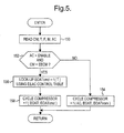
- Figure 4 depicts a flow diagram representative of a software routine periodically executed by the control unit 90 for controlling the operation of compressor 12 and temperature control door 56 according to this invention.
- the block 150 reads the various inputs from driver interface panel 92.
- the block 152 determines if the AC command is enabling air conditioning and the control mode CM indicates that the energy efficient control mode (EECM) is enabled. If one or more of the conditions is not met, the normal control mode is activated, and the block 154 controls compressor cycling (if enabled by the defrost mode or the AC command) based on a nominal evaporator outlet temperature target (EOATnom) such as 2 degrees C.
- EOATnom nominal evaporator outlet temperature target
- the compressor cycling of block 154 may involve a limit cycle control in which the compressor clutch 16 is engaged when the EOAT exceeds EOATnom, and disengaged when EOAT falls below (EOATnom - Khys), where Khys is a hysteresis constant. If the conditions of block 152 are met, the blocks 156 and 158 are executed to determine EOATcmd by table look-up as a function of temperature command T, substantially as depicted by the EOATcmd trace in Graph B of Figure 2, and to cycle compressor 12 on and off as required to bring EOAT into conformance with EOATcmd.
- the compressor cycling of block 158 may involve a limit cycle control in which the compressor clutch 16 is engaged when the EOAT exceeds EOATcmd, and disengaged when EOAT falls below (EOATcmd - Khys), where Khys is a hysteresis constant.
- the operator of the vehicle manipulates the temperature control selector 94 to control the discharge air temperature and to select either the normal control mode or the high fuel efficiency control mode.
- the spring 146 biases the knob 122 outward, engaging the normal control mode.
- the knob 122 is simply rotated away from the full cold position, the normal control mode is maintained; the cable 102 moves the temperature control door 56 to permit increased re-heating by the heater core 54, and the mechanical gain is calibrated so that the discharge air temperature corresponds to the temperature command T, assuming that control unit 90 maintains EOAT substantially equal to EOATnom.
- the operator may engage the high fuel efficiency mode by first depressing the knob 122, and then rotating it away from the full cold position.
- initial rotation of the knob 122 produces no movement of the temperature control door 56, and the control unit 90 cycles the compressor clutch to maintain EOAT substantially equal to EOATcmd, which is calibrated to produce a discharge air temperature corresponding to temperature command T.
- EOATcmd is maintained at a fixed value EOATmax, and the cable 102 moves the temperature control door 56 to permit increased re-heating by the heater core 54 in order to satisfy the temperature command T.
- the knob 122 is simply rotated back to the full cold setting, and the above-described decision process is repeated.
- the temperature selector 94 is operated in the normal control mode in which rotation of knob 122 produced continuous movement of the temperature control door 56, resulting in a linear relationship between the discharge air temperature and the temperature command T.
- control of the present invention achieves dual mode operation of a vehicle heating and air conditioning system with a manually adjusted temperature selector, with preservation of linearity between selector movement and discharge temperature adjustment regardless of the selected mode. While described in reference to the illustrated embodiment, it is expected that various modifications in addition to those mentioned above will occur to those skilled in the art. For example, a similar control function could be achieved with a linearly displaceable temperature selector; the system could include an indicator lamp to display the selected mode; and so on. Thus, it will be understood that systems incorporating these and other modifications may fall within the scope of this invention, which is defined by the appended claims.
Landscapes
- Physics & Mathematics (AREA)
- Thermal Sciences (AREA)
- Engineering & Computer Science (AREA)
- Mechanical Engineering (AREA)
- Air-Conditioning For Vehicles (AREA)
Applications Claiming Priority (2)
| Application Number | Priority Date | Filing Date | Title |
|---|---|---|---|
| US10/041,408 US6698512B2 (en) | 2002-01-07 | 2002-01-07 | Vehicle heating and air conditioning system including a dual mode manual temperature selector |
| US41408 | 2002-01-07 |
Publications (3)
| Publication Number | Publication Date |
|---|---|
| EP1325823A2 true EP1325823A2 (de) | 2003-07-09 |
| EP1325823A3 EP1325823A3 (de) | 2004-03-10 |
| EP1325823B1 EP1325823B1 (de) | 2008-06-18 |
Family
ID=21916360
Family Applications (1)
| Application Number | Title | Priority Date | Filing Date |
|---|---|---|---|
| EP02080236A Expired - Lifetime EP1325823B1 (de) | 2002-01-07 | 2002-12-12 | Fahrzeugklimaanlage mit mit zwei manuellen Betriebsarten |
Country Status (3)
| Country | Link |
|---|---|
| US (1) | US6698512B2 (de) |
| EP (1) | EP1325823B1 (de) |
| DE (1) | DE60227148D1 (de) |
Families Citing this family (8)
| Publication number | Priority date | Publication date | Assignee | Title |
|---|---|---|---|---|
| US6874574B2 (en) * | 2001-11-06 | 2005-04-05 | Delphi Technologies, Inc. | Energy efficient control method for a manually regulated vehicle heating and air conditioning system |
| US7904220B2 (en) * | 2004-07-26 | 2011-03-08 | GM Global Technology Operations LLC | Vehicular multifunction control system |
| US20080088577A1 (en) * | 2006-10-11 | 2008-04-17 | Gm Global Technology Operations, Inc. | Vehicular multifunction control system |
| US20090205354A1 (en) * | 2008-02-20 | 2009-08-20 | Applied Comfort Products Inc. | Frosting dehumidifier with enhanced defrost |
| US20090247063A1 (en) * | 2008-03-28 | 2009-10-01 | Stanley Armin Vollertsen | Solar powered vehicle ventilation system |
| US8403734B2 (en) * | 2009-02-20 | 2013-03-26 | Deere & Company | Vent control system |
| US20140216684A1 (en) * | 2013-02-01 | 2014-08-07 | Visteon Global Technologies, Inc. | Heating, ventilating, and air conditioning system with an exhaust gas thermal energy exchanger |
| KR102473503B1 (ko) * | 2018-04-06 | 2022-12-02 | 한온시스템 주식회사 | 차량용 공조장치 |
Citations (1)
| Publication number | Priority date | Publication date | Assignee | Title |
|---|---|---|---|---|
| US4383574A (en) | 1979-12-29 | 1983-05-17 | Diesel Kiki Co., Ltd. | Air conditioning system for automotive vehicles having discharge air temperature control function |
Family Cites Families (13)
| Publication number | Priority date | Publication date | Assignee | Title |
|---|---|---|---|---|
| JPS55148608A (en) * | 1979-05-10 | 1980-11-19 | Nissan Motor Co Ltd | Temperature controlling unit of air conditioner for automobile |
| US4484619A (en) * | 1979-06-18 | 1984-11-27 | Eaton Corporation | Vehicle temperature control system |
| JPS5650809A (en) * | 1979-10-01 | 1981-05-08 | Nippon Denso Co Ltd | Power-saving method and apparatus for controlling air-conditioning |
| JPS56103611A (en) * | 1980-01-16 | 1981-08-18 | Nippon Denso Co Ltd | Controlling method for power-saving air-conditioner |
| JPS57908A (en) * | 1980-06-02 | 1982-01-06 | Nissan Motor Co Ltd | Air conditioner for vehicle |
| JPS5777215A (en) * | 1980-11-04 | 1982-05-14 | Nissan Motor Co Ltd | Air conditioner for vehicle |
| JPS57100509U (de) * | 1980-12-12 | 1982-06-21 | ||
| JPS57134319A (en) * | 1981-02-12 | 1982-08-19 | Nippon Denso Co Ltd | Cooling power controller for car air conditioner |
| JPS57182511A (en) * | 1981-05-06 | 1982-11-10 | Hitachi Ltd | Temperature controller of motor car air conditioner |
| JPS58110317A (ja) * | 1981-12-23 | 1983-06-30 | Mitsubishi Heavy Ind Ltd | 車輌用空調装置 |
| US4766950A (en) * | 1984-05-31 | 1988-08-30 | Mitsubishi Jukogyo Kabushiki Kaisha | Controller for an air conditioner of vehicles |
| JPH01136809A (ja) * | 1987-11-20 | 1989-05-30 | Diesel Kiki Co Ltd | 自動車用空調装置のエアミツクスドア制御装置 |
| US5775415A (en) * | 1993-07-07 | 1998-07-07 | Nippondenso Co., Ltd. | Air conditioning system |
-
2002
- 2002-01-07 US US10/041,408 patent/US6698512B2/en not_active Expired - Lifetime
- 2002-12-12 EP EP02080236A patent/EP1325823B1/de not_active Expired - Lifetime
- 2002-12-12 DE DE60227148T patent/DE60227148D1/de not_active Expired - Lifetime
Patent Citations (1)
| Publication number | Priority date | Publication date | Assignee | Title |
|---|---|---|---|---|
| US4383574A (en) | 1979-12-29 | 1983-05-17 | Diesel Kiki Co., Ltd. | Air conditioning system for automotive vehicles having discharge air temperature control function |
Also Published As
| Publication number | Publication date |
|---|---|
| US6698512B2 (en) | 2004-03-02 |
| EP1325823B1 (de) | 2008-06-18 |
| DE60227148D1 (de) | 2008-07-31 |
| US20030127219A1 (en) | 2003-07-10 |
| EP1325823A3 (de) | 2004-03-10 |
Similar Documents
| Publication | Publication Date | Title |
|---|---|---|
| US6622500B1 (en) | Energy-efficient capacity control method for an air conditioning compressor | |
| US7121103B2 (en) | Vehicle air conditioning system | |
| EP1995095B1 (de) | Steuerverfahren für einen Verdichter mit variabler Verdrängung in einer leistungsoptimierten Klimaanlage | |
| EP1059183B1 (de) | Fahrzeugklimaanlage | |
| US6293115B1 (en) | Inlet air mixture control method for a vehicle air conditioning system | |
| US20020104324A1 (en) | Air conditioner for hybrid vehicle | |
| EP1145883B1 (de) | Verfahren zur Feuchtigkeitsregelung für ein Klimaregelungssystem mit variabler Verdrängung | |
| US6588222B1 (en) | Low-cost energy-efficient vehicle air conditioning system | |
| GB2389920A (en) | Controlling vehicle air conditioner during fuel cut control | |
| BRPI0709307A2 (pt) | sistema e método para o controle de um sistema de condicionamento do ar de um veìculo, com consumo de energia reduzido | |
| US6789617B1 (en) | Air mix damper device and vehicle air conditioner | |
| EP1308327B1 (de) | Energieeffizientes Kontrollverfahren einer manuellen gesteuerten Fahrzeugheiz- und Klimaanlage | |
| CN112606651A (zh) | 车载温度调节装置 | |
| JPS6192908A (ja) | 車輛用空気調和装置 | |
| JPH0142841B2 (de) | ||
| EP1325823B1 (de) | Fahrzeugklimaanlage mit mit zwei manuellen Betriebsarten | |
| US7013966B2 (en) | Vehicle air conditioner with hot-gas heater cycle | |
| US6352208B1 (en) | Air conditioning apparatus with air-temperature adjustment | |
| JP3239299B2 (ja) | 車両用空気調和装置 | |
| JPH06156045A (ja) | 車両用ヒートポンプ式空調装置 | |
| JPH11151936A (ja) | 車両用空調装置 | |
| JPS6227442Y2 (de) | ||
| JP2525696B2 (ja) | 自動車用空調装置の換気調節装置 | |
| KR0157756B1 (ko) | 센서를 이용한 자동차의 에어컨 자동 제어장치 | |
| KR20080099712A (ko) | 자동차용 공조 장치 제어 방법 |
Legal Events
| Date | Code | Title | Description |
|---|---|---|---|
| PUAI | Public reference made under article 153(3) epc to a published international application that has entered the european phase |
Free format text: ORIGINAL CODE: 0009012 |
|
| AK | Designated contracting states |
Designated state(s): AT BE BG CH CY CZ DE DK EE ES FI FR GB GR IE IT LI LU MC NL PT SE SI SK TR |
|
| AX | Request for extension of the european patent |
Extension state: AL LT LV MK RO |
|
| PUAL | Search report despatched |
Free format text: ORIGINAL CODE: 0009013 |
|
| AK | Designated contracting states |
Kind code of ref document: A3 Designated state(s): AT BE BG CH CY CZ DE DK EE ES FI FR GB GR IE IT LI LU MC NL PT SE SI SK TR |
|
| AX | Request for extension of the european patent |
Extension state: AL LT LV MK RO |
|
| 17P | Request for examination filed |
Effective date: 20040910 |
|
| AKX | Designation fees paid |
Designated state(s): DE FR GB |
|
| GRAP | Despatch of communication of intention to grant a patent |
Free format text: ORIGINAL CODE: EPIDOSNIGR1 |
|
| GRAS | Grant fee paid |
Free format text: ORIGINAL CODE: EPIDOSNIGR3 |
|
| GRAA | (expected) grant |
Free format text: ORIGINAL CODE: 0009210 |
|
| AK | Designated contracting states |
Kind code of ref document: B1 Designated state(s): DE FR GB |
|
| REG | Reference to a national code |
Ref country code: GB Ref legal event code: FG4D |
|
| REF | Corresponds to: |
Ref document number: 60227148 Country of ref document: DE Date of ref document: 20080731 Kind code of ref document: P |
|
| PLBE | No opposition filed within time limit |
Free format text: ORIGINAL CODE: 0009261 |
|
| STAA | Information on the status of an ep patent application or granted ep patent |
Free format text: STATUS: NO OPPOSITION FILED WITHIN TIME LIMIT |
|
| 26N | No opposition filed |
Effective date: 20090319 |
|
| REG | Reference to a national code |
Ref country code: DE Ref legal event code: R082 Ref document number: 60227148 Country of ref document: DE Representative=s name: BRP RENAUD UND PARTNER MBB, DE Ref country code: DE Ref legal event code: R081 Ref document number: 60227148 Country of ref document: DE Owner name: MAHLE INTERNATIONAL GMBH, DE Free format text: FORMER OWNER: DELPHI TECHNOLOGIES, INC., TROY, MICH., US Ref country code: DE Ref legal event code: R082 Ref document number: 60227148 Country of ref document: DE Representative=s name: BRP RENAUD UND PARTNER MBB RECHTSANWAELTE PATE, DE |
|
| REG | Reference to a national code |
Ref country code: FR Ref legal event code: PLFP Year of fee payment: 14 |
|
| REG | Reference to a national code |
Ref country code: FR Ref legal event code: PLFP Year of fee payment: 15 |
|
| REG | Reference to a national code |
Ref country code: GB Ref legal event code: 732E Free format text: REGISTERED BETWEEN 20161208 AND 20161214 |
|
| REG | Reference to a national code |
Ref country code: FR Ref legal event code: PLFP Year of fee payment: 16 |
|
| REG | Reference to a national code |
Ref country code: FR Ref legal event code: TP Owner name: MAHLE INTERNATIONAL GMBH, DE Effective date: 20180103 |
|
| PGFP | Annual fee paid to national office [announced via postgrant information from national office to epo] |
Ref country code: FR Payment date: 20181227 Year of fee payment: 17 Ref country code: GB Payment date: 20181221 Year of fee payment: 17 |
|
| PGFP | Annual fee paid to national office [announced via postgrant information from national office to epo] |
Ref country code: DE Payment date: 20190228 Year of fee payment: 17 |
|
| REG | Reference to a national code |
Ref country code: DE Ref legal event code: R119 Ref document number: 60227148 Country of ref document: DE |
|
| GBPC | Gb: european patent ceased through non-payment of renewal fee |
Effective date: 20191212 |
|
| PG25 | Lapsed in a contracting state [announced via postgrant information from national office to epo] |
Ref country code: FR Free format text: LAPSE BECAUSE OF NON-PAYMENT OF DUE FEES Effective date: 20191231 Ref country code: DE Free format text: LAPSE BECAUSE OF NON-PAYMENT OF DUE FEES Effective date: 20200701 Ref country code: GB Free format text: LAPSE BECAUSE OF NON-PAYMENT OF DUE FEES Effective date: 20191212 |