EP1326320A2 - Moteur à manchon d'entrefer en matériau composite - Google Patents
Moteur à manchon d'entrefer en matériau composite Download PDFInfo
- Publication number
- EP1326320A2 EP1326320A2 EP02257388A EP02257388A EP1326320A2 EP 1326320 A2 EP1326320 A2 EP 1326320A2 EP 02257388 A EP02257388 A EP 02257388A EP 02257388 A EP02257388 A EP 02257388A EP 1326320 A2 EP1326320 A2 EP 1326320A2
- Authority
- EP
- European Patent Office
- Prior art keywords
- rotor
- composite
- stator
- electric motor
- motor according
- Prior art date
- Legal status (The legal status is an assumption and is not a legal conclusion. Google has not performed a legal analysis and makes no representation as to the accuracy of the status listed.)
- Withdrawn
Links
Images


Classifications
-
- H—ELECTRICITY
- H02—GENERATION; CONVERSION OR DISTRIBUTION OF ELECTRIC POWER
- H02K—DYNAMO-ELECTRIC MACHINES
- H02K5/00—Casings; Enclosures; Supports
- H02K5/04—Casings or enclosures characterised by the shape, form or construction thereof
- H02K5/12—Casings or enclosures characterised by the shape, form or construction thereof specially adapted for operating in liquid or gas
- H02K5/128—Casings or enclosures characterised by the shape, form or construction thereof specially adapted for operating in liquid or gas using air-gap sleeves or air-gap discs
Definitions
- This invention relates to electric motors having stators and rotors which are provided with canning arrangements to protect them from intrusion of water when submerged.
- Many conventional canning arrangements for electric motor rotors and stators include a metal enclosure made, for example, by welding sheet metal parts with a thickness of about 0.025 inches or more to provide a water-tight seal for the rotor or stator.
- a metal enclosure made, for example, by welding sheet metal parts with a thickness of about 0.025 inches or more to provide a water-tight seal for the rotor or stator.
- Such conductive material introduces eddy current losses which reduce the motor efficiency and, in some cases, increase the size of the motor.
- surface irregu larities such as grooves or projections are formed on the surfaces of the can to promote the flow of cooling water through the gap between the stator and the rotor, irregularities in flux linkage are introduced and eddy current losses are increased significantly.
- the metallic can is eliminated by encapsulating the rotor and stator in a layer of composite material. Because the composite material is not rigid and is subject to damage, however, this introduces dimensional control difficulties and interferes with maintenance of
- the Blakeley et al. Patent No. 5,122,704 discloses a composite rotor sleeve for a rotor composed of a continuous film of polyimide material on its radially inner surface surrounding the rotor and successive layers of plies formed from wound fibrous material, such as carbon fibers impregnated in a matrix of resin in which the carbon fibers extends circumferentially around the rotor in the inner plies and extend at angles to the diameter of the rotor in outer layers to provide strength.
- the assembly of composite layers prevents leakage of liquid between the rotor and the space between the rotor and stator.
- the Smith et al. Patent No. 6,069,421 discloses an electric motor in which the stator and the rotor are encapsulated in composite resin material with inner and outer composite layers made from high strength resin containing high modulus fibers, such as fiberglass, graphite, carbon, boron, quartz or arimid fiber material.
- a stator for a submerged motor is encapsulated in a carbon fiber-reinforced plastic housing having components including end caps which are threaded to cylindrical members to provide a mechanical connection between them.
- the Yamamoto et al. Patent No. 4,496,866 discloses a submersible electric motor having a stator formed from an inner thin metal cylinder surrounded by a stator core and coil and a molded resin member formed to surround the outer wall having two end faces adhesively joined to the inner cylinder.
- the Nakamura et al. Patent No. 5,490,319 also discloses an electric motor with an encapsulated stator having a core and coils embedded in plastic resin with resin molded cans that isolate the encapsulating resin from the rotor section.
- the Ineson Patent No. 5,334,897 describes a sealed electric motor having interfitting metallic housing members and an overmolded plastic casing
- the Bresolin Patent No. 5,767, 606 describes a method for manufacturing a sealed synchronous electric motor, particularly for submersible pumps by which the entire stator of the motor is embedded into a matrix of insulating resin.
- Veronesi et al. Patents Nos. 5,185,545 and 5,252,785 disclose canned rotors for electric motors in which the outer surface of the rotor has a spiral groove to help circulate water through the gap between the rotor and the stator.
- Another object to the invention is to provide a composite canning arrangement for electric motor components which permits disassembly for motor maintenance.
- a further object to the invention is to provide a canning arrangement having a contoured surface to promote or inhibit water flow through the gap between the stator and rotor without introducing eddy current losses.
- a composite canning arrangement for rotors or stators in which a pre-shaped composite component is affixed by mechanical connectors such as screws or the like to a support member and sealed to the support member with O-rings, gaskets or the like.
- the pre-shaped composite component may have a surface which is contoured to promote or inhibit water flow in the gap between the stator and rotor during operation.
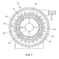
- an electric motor 10 illustrated in Fig. 1 includes a stator 12 provided with a composite canning arrangement 14 so as to be capable of being submerged in a liquid such as water.
- the stator has a central opening 16 in which a rotor 18, also provided with a composite canning arrangement 20, is supported for rotation.
- the stator 12 is supplied with power through cables 22 for energizing stator windings 24, schematically illustrated in Fig. 5, which are received in aligned slots 26, shown in Fig. 4, formed in an assembly of ring-shaped laminations 30 made of magnetic material.
- the laminations 30 and windings 24 are housed in a support assembly 32 consisting of mechanically connected components 34, 36, 38 and 40 forming an enclosure 41 which is sealed by the composite canning arrangement 14.
- a cylindrical composite can member 42 is mechanically affixed to the inner surface of the support assembly 32 by attaching devices such as screws 44 which are located outside the path of the magnetic flux extending between the rotor 18 and the stator 12.
- the cylindrical composite can member 42 is a rigid component pre-formed from a fiber-reinforced organic or inorganic polymer composite, the fibers being chosen, for example, from glass, aramid, carbon, polyester and quartz material.
- the composite can member 42 is made using a dry lay-up resin transfer molding or a wet or pre-impregnated filament winding technique to provide sufficient rigidity to the can member 42 to maintain its cylindrical shape accurately under all environmental conditions and resist damage or deformation from contact with other component.
- a series of O-rings 48 are mounted in grooves 50 in the support assembly 32 and the support assembly members 34, 36, 38 and 40 are provided with seals 52 at the joints between them.
- the housing formed by the support assembly members provides a water-tight seal while at the same time permitting convenient disassembly for repair and maintenance purposes.
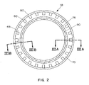
- the rotor 18 is mounted on a central axial shaft 60 and has an annular outer rotor component 62 supported from the shaft 60 by radial arms 64.
- the annular rotor component 62 supports a circumferential array of angularly spaced permanent magnets 66 received in openings 68 in the annular rotor component 62, the magnets being oriented to produce magnetic flux through adjacent pole pieces 70 which links the windings 24 in the stator 12 as the rotor 18 turns within the stator.
- each of the slots 68 receives a row of individual magnets 60 aligned in the axial direction of the rotor and, as shown in Fig. 3B, the rotor pole piece 70 consists of an array of circular lamination members 72 and is affixed by screws 74 to an inner cylindrical rotor member 76, the assembly being retained together by end pieces 78 at each end.
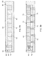
- the rotor assembly includes an outer cylindrical can member 80, made of composite material of the same type described above with respect to the stator can member 42, which is retained against the end pieces 78 by screws 82 and is sealed to the end pieces 78 by O-rings 84 received in grooves 86.
- another rigid cylindrical composite can member 90 is similarly affixed with appropriate sealing rings to the inner surface of the rotor component 62 to complete the sealing arrangement.
- the rotor assembly can conveniently be disassembled for repair or maintenance and reassembled without destroying the canning arrangement.
- the exposed surface of the outer composite cylindrical can member 80 of the rotor may be shaped with projections arranged to promote or inhibit flow of liquid through the space 92.
- Fig. 6A is a plan view and Fig. 6A is a cross-sectional view of a portion of the outer composite can member 80 of the rotor which is formed with a corrugation pattern consisting of parallel ridges 96 which extend circumferentially around the outer surface of the composite can member 80 so as to inhibit flow of liquid through the gap 92 between the stator and rotor.
- FIG. 7A and 7B Another corrugation pattern 100, shown in Figs. 7A and 7B, includes a series of parallel ridges 102 projecting from the outer surface of the composite rotor can member 80 at an angle to a plane perpendicular to the axis of the rotor, thereby promoting flow of liquid in the direction 104 through the space 92 between the stator and the rotor as the rotor rotates in the direction 106. In this way the flow of water through the space 92 which provides cooling can be manipulated and used as a design parameter. Because the composite rotor and stator canning member are made of fiber reinforced rigid material, those components are resistant to damage and a small but accurate dimension of the space 92 between the rotor and the stator can be maintained during operation.
- the composite can member 20 for the motor rotor may be a preformed cylindrical member installed independently between end plates using bolts and clamping plates or, alternatively, it may be wound in place on the outer surface of the motor with a corrugation pattern 96 or 100 subsequently formed in its outer surface.
Landscapes
- Engineering & Computer Science (AREA)
- Power Engineering (AREA)
- Motor Or Generator Frames (AREA)
Applications Claiming Priority (2)
| Application Number | Priority Date | Filing Date | Title |
|---|---|---|---|
| US10/040,833 US20030127924A1 (en) | 2002-01-08 | 2002-01-08 | Composite canning arrangement for motors |
| US40833 | 2002-01-08 |
Publications (2)
| Publication Number | Publication Date |
|---|---|
| EP1326320A2 true EP1326320A2 (fr) | 2003-07-09 |
| EP1326320A3 EP1326320A3 (fr) | 2005-10-26 |
Family
ID=21913218
Family Applications (1)
| Application Number | Title | Priority Date | Filing Date |
|---|---|---|---|
| EP02257388A Withdrawn EP1326320A3 (fr) | 2002-01-08 | 2002-10-24 | Moteur à manchon d'entrefer en matériau composite |
Country Status (2)
| Country | Link |
|---|---|
| US (1) | US20030127924A1 (fr) |
| EP (1) | EP1326320A3 (fr) |
Cited By (2)
| Publication number | Priority date | Publication date | Assignee | Title |
|---|---|---|---|---|
| EP2375546A3 (fr) * | 2010-04-12 | 2015-08-19 | Hamilton Sundstrand Space Systems International, Inc. | Implémentation de barrière non métallique dans un moteur électrique |
| FR3042432A1 (fr) * | 2015-10-19 | 2017-04-21 | Dab Pumps Spa | Outillage pour l'assemblage d'un moteur electrique a aimants permanents a utiliser en particulier dans des dispositifs de pompage, moteur electrique realise avec un tel outillage et electropompe comprenant un tel moteur electrique |
Families Citing this family (9)
| Publication number | Priority date | Publication date | Assignee | Title |
|---|---|---|---|---|
| US20110044831A1 (en) * | 2008-05-06 | 2011-02-24 | Christopher E Cunningham | Motor with high pressure rated can |
| US8777596B2 (en) * | 2008-05-06 | 2014-07-15 | Fmc Technologies, Inc. | Flushing system |
| JP2013027228A (ja) * | 2011-07-25 | 2013-02-04 | Seiko Epson Corp | 電気機械装置、並びに、電機機械装置を用いた移動体およびロボット |
| DE102017102141A1 (de) * | 2017-02-03 | 2018-08-09 | Dr. Ing. H.C. F. Porsche Aktiengesellschaft | Verfahren zur Herstellung einer elektrischen Antriebsmaschine und elektrische Antriebsmaschine |
| DE102021120993A1 (de) * | 2021-08-12 | 2023-02-16 | Dr. Ing. H.C. F. Porsche Aktiengesellschaft | Elektrische Maschine und Kraftfahrzeug |
| EP4145680A1 (fr) * | 2021-09-03 | 2023-03-08 | Skf Magnetic Mechatronics | Machine électrique rotative et rotor pour une telle machine |
| EP4145681A1 (fr) * | 2021-09-03 | 2023-03-08 | SKF Magnetic Mechatronics | Machine rotative électrique et ensemble stator pour une telle machine |
| EP4145682A1 (fr) | 2021-09-03 | 2023-03-08 | SKF Magnetic Mechatronics | Machine électrique tournante et ensemble stator pour une telle machine |
| US20240396396A1 (en) * | 2021-10-14 | 2024-11-28 | Schlumberger Technology Corporation | Tooling for encapsulated esp stators |
Family Cites Families (45)
| Publication number | Priority date | Publication date | Assignee | Title |
|---|---|---|---|---|
| US1678380A (en) * | 1924-07-25 | 1928-07-24 | Cooper Thomas Lancelot Reed | Dynamo-electric machine |
| US2299406A (en) * | 1941-05-08 | 1942-10-20 | Breeze Corp | Flowmeter |
| CH305818A (de) * | 1950-11-02 | 1955-03-15 | Bayer Ag | Pumpenaggregat. |
| US2725012A (en) * | 1952-03-22 | 1955-11-29 | Mcgraw Electric Co | Motor-pump unit |
| US2956188A (en) * | 1956-04-06 | 1960-10-11 | Fostoria Corp | Sealless motor for valve operation |
| US2958292A (en) * | 1956-10-22 | 1960-11-01 | Allis Chalmers Mfg Co | Canned motor |
| US3067690A (en) * | 1958-12-01 | 1962-12-11 | Kramer Hermann | Pump unit with canned electric motor |
| US2993449A (en) * | 1959-03-09 | 1961-07-25 | Hydratomic Engineering Corp | Motor-pump |
| US3143676A (en) * | 1960-10-17 | 1964-08-04 | Allis Chalmers Mfg Co | Sealing arrangement for canned pumps |
| BE644859A (fr) * | 1963-03-06 | |||
| BE651914A (fr) * | 1963-08-16 | |||
| US3309009A (en) * | 1964-05-12 | 1967-03-14 | Culk Raimund | Refrigerating compressors |
| JPS4828842B1 (fr) * | 1968-10-01 | 1973-09-05 | ||
| US3629628A (en) * | 1970-07-06 | 1971-12-21 | Gen Motors Corp | Cooling arrangement for a squirrel cage rotor assembly |
| US3758799A (en) * | 1972-01-06 | 1973-09-11 | Gen Electric | Dynamoelectric machine |
| US3873861A (en) * | 1973-06-15 | 1975-03-25 | Richard Halm | Electric motor, especially a squirrel-cage motor |
| CA1177328A (fr) * | 1981-01-16 | 1984-11-06 | Toshiaki Tsutsui | Motopompe sous enveloppe a fluide de refroidissement pour le refoulement de liquides tres chauds |
| US4496866A (en) * | 1981-01-17 | 1985-01-29 | Mitsubishi Denki Kabushiki Kaisha | Submersible electric motor and method of manufacturing the same |
| JPS5996843A (ja) * | 1982-11-19 | 1984-06-04 | Hitachi Ltd | 水中モータ |
| US4598218A (en) * | 1983-08-17 | 1986-07-01 | Sundstrand Corporation | High speed rotor with removable can |
| US4655682A (en) * | 1985-09-30 | 1987-04-07 | United Technologies Corporation | Compressor stator assembly having a composite inner diameter shroud |
| US4633113A (en) * | 1985-10-16 | 1986-12-30 | Sundstrand Corporation | Side plate construction for permanent magnet rotor |
| GB8702461D0 (en) * | 1987-02-04 | 1987-03-11 | Gec Machines Ltd | Pump motor |
| DE8709209U1 (de) * | 1987-07-03 | 1987-09-10 | Uranit GmbH, 52428 Jülich | Elektromotor |
| US4775291A (en) * | 1987-07-27 | 1988-10-04 | Binks Manufacturing Company | Magnetic clutch drive and thrust balancing mechanism for rotary pumps |
| DE3818832A1 (de) * | 1988-06-03 | 1989-12-07 | Uranit Gmbh | Spalttopf fuer stopfbuchsenlose elektrische oder magnetische antriebsaggregate |
| FR2650923B1 (fr) * | 1989-08-11 | 1995-05-24 | Salmson Pompes | Stator de moteur electrique et moteur electrique comportant un tel stator |
| US5289068A (en) * | 1990-08-23 | 1994-02-22 | Westinghouse Electric Corp. | Two-stage submersible propulsor unit for water vehicles |
| US5252875A (en) * | 1990-08-23 | 1993-10-12 | Westinghouse Electric Corp. | Integral motor propulsor unit for water vehicles with plural electric motors driving a single propeller |
| US5185545A (en) * | 1990-08-23 | 1993-02-09 | Westinghouse Electric Corp. | Dual propeller shock resistant submersible propulsor unit |
| US5122704A (en) * | 1990-10-25 | 1992-06-16 | Sundstrand Corporation | Composite rotor sleeve |
| DK0504994T3 (da) * | 1991-03-20 | 1997-07-07 | Gold Star Co | Rotor til en kapslet motor til en kapslet motorpumpe |
| US5490319A (en) * | 1992-01-29 | 1996-02-13 | Ebara Corporation | Thermotropic liquid crystal polymer composition and insulator |
| US5334897A (en) * | 1993-05-24 | 1994-08-02 | North American Philips Corporation | Electric motor with encased housing |
| JPH07203645A (ja) * | 1993-12-30 | 1995-08-04 | Mabuchi Motor Co Ltd | 小型モータ及びその回転子の製造方法 |
| EP0678964B1 (fr) * | 1994-04-20 | 1997-07-30 | Sulzer Innotec Ag | Elément de séparation et machine avec élément de séparation |
| FR2720562B1 (fr) * | 1994-05-25 | 1996-08-14 | Jeumont Ind | Machine tournante chemisée. |
| US5627420A (en) * | 1994-12-16 | 1997-05-06 | Westinghouse Electric Corporation | Pump powered by a canned electric motor having a removable stator cartridge |
| JP3444324B2 (ja) * | 1995-11-30 | 2003-09-08 | いすゞ自動車株式会社 | 永久磁石式渦電流減速装置 |
| US5763973A (en) * | 1996-10-30 | 1998-06-09 | Imo Industries, Inc. | Composite barrier can for a magnetic coupling |
| DE19718791A1 (de) * | 1997-05-03 | 1998-11-05 | Mannesmann Vdo Ag | Fördereinheit |
| US5898245A (en) * | 1997-06-12 | 1999-04-27 | Franklin Electric Company, Inc. | Self-lubricating submersible electric motor |
| DE19926530A1 (de) * | 1999-06-10 | 2000-12-14 | Wilo Gmbh | Spalttopf aus faserverstärktem Kunststoff und Formwerkzeug hierfür |
| US6069421A (en) * | 1999-08-30 | 2000-05-30 | Electric Boat Corporation | Electric motor having composite encapsulated stator and rotor |
| US6452301B1 (en) * | 2001-11-02 | 2002-09-17 | Electric Boat Corporation | Magnet retention arrangement for high speed rotors |
-
2002
- 2002-01-08 US US10/040,833 patent/US20030127924A1/en not_active Abandoned
- 2002-10-24 EP EP02257388A patent/EP1326320A3/fr not_active Withdrawn
Cited By (4)
| Publication number | Priority date | Publication date | Assignee | Title |
|---|---|---|---|---|
| EP2375546A3 (fr) * | 2010-04-12 | 2015-08-19 | Hamilton Sundstrand Space Systems International, Inc. | Implémentation de barrière non métallique dans un moteur électrique |
| FR3042432A1 (fr) * | 2015-10-19 | 2017-04-21 | Dab Pumps Spa | Outillage pour l'assemblage d'un moteur electrique a aimants permanents a utiliser en particulier dans des dispositifs de pompage, moteur electrique realise avec un tel outillage et electropompe comprenant un tel moteur electrique |
| CN106877582A (zh) * | 2015-10-19 | 2017-06-20 | 戴博邦浦股份有限公司 | 用于组装永磁电机的装置、由该装置制成的电机及电动泵 |
| US10498205B2 (en) | 2015-10-19 | 2019-12-03 | Dab Pumps S.P.A. | Apparatus for assembling a permanent-magnet electric motor to be used particularly in pumping devices, electric motor produced with such apparatus, and electric pump comprising such electric motor |
Also Published As
| Publication number | Publication date |
|---|---|
| EP1326320A3 (fr) | 2005-10-26 |
| US20030127924A1 (en) | 2003-07-10 |
Similar Documents
| Publication | Publication Date | Title |
|---|---|---|
| US6069421A (en) | Electric motor having composite encapsulated stator and rotor | |
| CN110447160B (zh) | 具有多个一体化在网格结构中的单元磁体的磁体结构 | |
| EP0353042B1 (fr) | Générateur électrique à champ radial | |
| EP0223612B1 (fr) | Rotor pour une machine électrique | |
| US6847145B2 (en) | Encapsulated permanent magnet motor rotor | |
| KR102218809B1 (ko) | 회전자, 회전 전기 및 회전자의 제조 방법 | |
| US6104115A (en) | Method for fabricating a permanent magnet rotor, and rotor obtained by said method | |
| US6700273B1 (en) | Gas transfer machine | |
| KR101237020B1 (ko) | 완전 방수구조를 갖는 유체 펌프 | |
| EP1326320A2 (fr) | Moteur à manchon d'entrefer en matériau composite | |
| US7471026B2 (en) | Brushless electric motor | |
| US6963151B2 (en) | Composite lamina arrangement for canning of motors | |
| JP5555510B2 (ja) | キャンドモータ及びキャンドモータポンプ | |
| KR102527294B1 (ko) | 축방향 자속 회전기기 | |
| CN105305749A (zh) | 定子无铁心Halbach永磁阵列轴向磁通电机 | |
| US7084548B1 (en) | Low cost high speed electrical machine | |
| US20240258846A1 (en) | Stator assembly for an axial flux motor | |
| KR20110103955A (ko) | 전기 기계 및 이의 고정자부의 제조 방법 | |
| US20190273406A1 (en) | Electric machines | |
| JP2000354345A (ja) | 攻撃的な媒体の中で使用するために設けられた電動モータ | |
| US11233430B2 (en) | Rotor of synchronous motor with reinforcement member for pressing magnet | |
| CA3133003A1 (fr) | Moteur a aimant permanent pour pompe submersible electrique | |
| US10298091B2 (en) | Rotor of rotating motor, rotating motor, and air-conditioning apparatus | |
| GB2145882A (en) | Partition structure for a dynamo-electric machine | |
| KR102684606B1 (ko) | 축방향 자속 회전기기 |
Legal Events
| Date | Code | Title | Description |
|---|---|---|---|
| PUAI | Public reference made under article 153(3) epc to a published international application that has entered the european phase |
Free format text: ORIGINAL CODE: 0009012 |
|
| AK | Designated contracting states |
Designated state(s): AT BE BG CH CY CZ DE DK EE ES FI FR GB GR IE IT LI LU MC NL PT SE SK TR |
|
| AX | Request for extension of the european patent |
Extension state: AL LT LV MK RO SI |
|
| PUAL | Search report despatched |
Free format text: ORIGINAL CODE: 0009013 |
|
| AK | Designated contracting states |
Kind code of ref document: A3 Designated state(s): AT BE BG CH CY CZ DE DK EE ES FI FR GB GR IE IT LI LU MC NL PT SE SK TR |
|
| AX | Request for extension of the european patent |
Extension state: AL LT LV MK RO SI |
|
| AKX | Designation fees paid | ||
| REG | Reference to a national code |
Ref country code: DE Ref legal event code: 8566 |
|
| STAA | Information on the status of an ep patent application or granted ep patent |
Free format text: STATUS: THE APPLICATION IS DEEMED TO BE WITHDRAWN |
|
| 18D | Application deemed to be withdrawn |
Effective date: 20060427 |