EP1326488A2 - Automatische Zufuhrvorrichtung für streifenweise angeordnete Kontaktelemente - Google Patents
Automatische Zufuhrvorrichtung für streifenweise angeordnete Kontaktelemente Download PDFInfo
- Publication number
- EP1326488A2 EP1326488A2 EP02028026A EP02028026A EP1326488A2 EP 1326488 A2 EP1326488 A2 EP 1326488A2 EP 02028026 A EP02028026 A EP 02028026A EP 02028026 A EP02028026 A EP 02028026A EP 1326488 A2 EP1326488 A2 EP 1326488A2
- Authority
- EP
- European Patent Office
- Prior art keywords
- component
- pickup
- carrier
- feeder
- pickup location
- Prior art date
- Legal status (The legal status is an assumption and is not a legal conclusion. Google has not performed a legal analysis and makes no representation as to the accuracy of the status listed.)
- Granted
Links
Images






Classifications
-
- H—ELECTRICITY
- H01—ELECTRIC ELEMENTS
- H01R—ELECTRICALLY-CONDUCTIVE CONNECTIONS; STRUCTURAL ASSOCIATIONS OF A PLURALITY OF MUTUALLY-INSULATED ELECTRICAL CONNECTING ELEMENTS; COUPLING DEVICES; CURRENT COLLECTORS
- H01R43/00—Apparatus or processes specially adapted for manufacturing, assembling, maintaining, or repairing of line connectors or current collectors or for joining electric conductors
- H01R43/20—Apparatus or processes specially adapted for manufacturing, assembling, maintaining, or repairing of line connectors or current collectors or for joining electric conductors for assembling or disassembling contact members with insulating base, case or sleeve
- H01R43/205—Apparatus or processes specially adapted for manufacturing, assembling, maintaining, or repairing of line connectors or current collectors or for joining electric conductors for assembling or disassembling contact members with insulating base, case or sleeve with a panel or printed circuit board
-
- H—ELECTRICITY
- H01—ELECTRIC ELEMENTS
- H01R—ELECTRICALLY-CONDUCTIVE CONNECTIONS; STRUCTURAL ASSOCIATIONS OF A PLURALITY OF MUTUALLY-INSULATED ELECTRICAL CONNECTING ELEMENTS; COUPLING DEVICES; CURRENT COLLECTORS
- H01R43/00—Apparatus or processes specially adapted for manufacturing, assembling, maintaining, or repairing of line connectors or current collectors or for joining electric conductors
- H01R43/02—Apparatus or processes specially adapted for manufacturing, assembling, maintaining, or repairing of line connectors or current collectors or for joining electric conductors for soldered or welded connections
- H01R43/0256—Apparatus or processes specially adapted for manufacturing, assembling, maintaining, or repairing of line connectors or current collectors or for joining electric conductors for soldered or welded connections for soldering or welding connectors to a printed circuit board
-
- Y—GENERAL TAGGING OF NEW TECHNOLOGICAL DEVELOPMENTS; GENERAL TAGGING OF CROSS-SECTIONAL TECHNOLOGIES SPANNING OVER SEVERAL SECTIONS OF THE IPC; TECHNICAL SUBJECTS COVERED BY FORMER USPC CROSS-REFERENCE ART COLLECTIONS [XRACs] AND DIGESTS
- Y10—TECHNICAL SUBJECTS COVERED BY FORMER USPC
- Y10T—TECHNICAL SUBJECTS COVERED BY FORMER US CLASSIFICATION
- Y10T156/00—Adhesive bonding and miscellaneous chemical manufacture
- Y10T156/19—Delaminating means
- Y10T156/1906—Delaminating means responsive to feed or shape at delamination
-
- Y—GENERAL TAGGING OF NEW TECHNOLOGICAL DEVELOPMENTS; GENERAL TAGGING OF CROSS-SECTIONAL TECHNOLOGIES SPANNING OVER SEVERAL SECTIONS OF THE IPC; TECHNICAL SUBJECTS COVERED BY FORMER USPC CROSS-REFERENCE ART COLLECTIONS [XRACs] AND DIGESTS
- Y10—TECHNICAL SUBJECTS COVERED BY FORMER USPC
- Y10T—TECHNICAL SUBJECTS COVERED BY FORMER US CLASSIFICATION
- Y10T29/00—Metal working
- Y10T29/51—Plural diverse manufacturing apparatus including means for metal shaping or assembling
- Y10T29/5193—Electrical connector or terminal
-
- Y—GENERAL TAGGING OF NEW TECHNOLOGICAL DEVELOPMENTS; GENERAL TAGGING OF CROSS-SECTIONAL TECHNOLOGIES SPANNING OVER SEVERAL SECTIONS OF THE IPC; TECHNICAL SUBJECTS COVERED BY FORMER USPC CROSS-REFERENCE ART COLLECTIONS [XRACs] AND DIGESTS
- Y10—TECHNICAL SUBJECTS COVERED BY FORMER USPC
- Y10T—TECHNICAL SUBJECTS COVERED BY FORMER US CLASSIFICATION
- Y10T29/00—Metal working
- Y10T29/53—Means to assemble or disassemble
- Y10T29/5313—Means to assemble electrical device
- Y10T29/53191—Means to apply vacuum directly to position or hold work part
-
- Y—GENERAL TAGGING OF NEW TECHNOLOGICAL DEVELOPMENTS; GENERAL TAGGING OF CROSS-SECTIONAL TECHNOLOGIES SPANNING OVER SEVERAL SECTIONS OF THE IPC; TECHNICAL SUBJECTS COVERED BY FORMER USPC CROSS-REFERENCE ART COLLECTIONS [XRACs] AND DIGESTS
- Y10—TECHNICAL SUBJECTS COVERED BY FORMER USPC
- Y10T—TECHNICAL SUBJECTS COVERED BY FORMER US CLASSIFICATION
- Y10T29/00—Metal working
- Y10T29/53—Means to assemble or disassemble
- Y10T29/5313—Means to assemble electrical device
- Y10T29/53261—Means to align and advance work part
Definitions
- the invention is directed to an automatic feeder for strip-supported electrical components and its method of operation, and in particular for supplying discrete components from a supply of components supported from a continuous strip for pickup by any one of conventional pick and- place machines.
- Pick-and-place machines are well known and widely used in the populating of printed circuit boards or cards (PCBs) by components using surfacemount technology (SMT). They offer the capability of precision in component placement, and speed in picking up a component from its source and placing it typically on a solder-paste covered pad on the PCB. Often the components are removed from small receptacles on a tape carrier.
- SMT surfacemount technology
- components are often supplied on a strip unreeled from a reel supplied to the PCB maker by the component supplier.
- USP 5,605,430 describes a feeder actuated by a pick-and-place machine for components connected to each other at their base to form a strip, which patent disclosure is hereby incorporated by reference.
- the beveled end of the pin or post which is adapted to be picked up the conventional vacuum nozzle of a standard pick-and-place machine, is positioned above its base and thus the beveled pickup end rises free of the base and free of adjacent components and when separated from its neighbor is ready for pickup.
- some suppliers supply components suspended by their beveled pickup end from a common carrier. In this case, the beveled pickup end is obstructed by the carrier.
- the carrier may obstruct the vacuum nozzle when it arrives to pickup the separated component.
- the feeder described in USP 5,605,430 is incapable of feeding such a strip of components for automatic pickup by pick-and-place machines.
- a principal object of the invention is an automatic feeder for components suspended from a common carrier for pickup by a conventional pick-and-place machine.
- a further object of the invention is a low cost high speed automatic feeder compatible with various pick-and-place machines and easily capable of feeding various diameters and lengths of components such as pins or posts to the pick-and-place machine.
- Still another object of the invention is a method of separating components from a strip of components and making them available for pickup by a conventional pick-and-place machine.
- a novel feeder construction that is easily interfaced to a variety of conventional pick-and-place machines and can readily and reliably feed components suspended from a common carrier after separation for pickup by the pick-and-place machine.
- the carrier with suspended components is fed along a path spaced laterally from the location where the component must be placed to be picked up by the descending pickup arm of the pick-and-place machine. The lead component when separated from the strip must then be moved laterally to the pickup location.
- the feeder parts that separate the lead component from the carrier and move it to the pickup location comprise a component-retaining means having a clamping surface and means for temporarily holding the separated component against the clamping surface between the time that the component is separated and the time that it is ready for pickup.
- the timing of the feeder operation is controlled such that the holding means releases the component and the element forming the clamping surface is moved away from the pickup location before the pickup arm with the engaged component departs the pickup location.
- the feeder parts are arranged such that the part that actually separates the lead component from the carrier accomplishes this by engaging the component near where it is connected to the carrier while simultaneously the part forming the clamping surface also engages a portion of the component further removed from its connection to the carrier to ensure a clean shearing without bending of the component from the carrier.
- the component-separating means comprises means for straightening the components on the strip before they have reached the separation position.
- the feeder of the invention is capable of handling components suspended from a common carrier.
- Pin examples are described and illustrated in USP 5,451,174, whose contents are hereby incorporated by reference.
- Fig. 12 of that patent illustrates a carrier strip 75 having a pin 80 attached. The carrier is shown positioned below the pin for those instances where the pin beveled end, when separated from the carrier, is to be inserted into a hole in a substrate.
- the carrier position is inverted so that the pins are suspended from the carrier positioned above them.
- the feeder of the invention can also be readily adapted to handle a wide variety of SMT components, and a wide variety of SMT pins and posts of different configurations, and thus the claims are not to be limited to the pins specifically illustrated in the '174 patent or used to illustrate the invention in the specific embodiment.
- Fig. 1 is for SMT stamped pins and is a self-contained high-speed precision electropneumatic mechanical apparatus which presents discrete separated SMT pins-from a strip of pins suspended by their beveled end from a common carrier to a pickup location for a vacuum nozzle of a surface-mount pick-and-place machine.
- the pins are integral with the carrier, are homogenous, and are stamped from a continuous strip of material appropriate for the specific application, typically copper or a copper alloy.
- MiniFoot surface mount pins are sold by the assignee under the trademarked names MiniFoot surface mount pins.
- the feeder always holds or clamps the separated pin in the pickup location until the pick-and-place machine retrieves the pin, after which the feeder presents the next following pin from the strip into the vacant pickup location.
- the separated pin retainer is preferably comprised of a small V-block forming a clamping surface facing the pickup location and which block moves in a horizontal direction laterally to the pin and the carrier, and a rotating spring-loaded retaining lever directly opposite the clamping surface of the V-block which lever tightly presses the pin against the V-block clamping surface.
- the pin retainer cooperates with a pin separator which is used to shear the pin from its carrier support while the separated pin is simultaneously clamped to the V-block by the retaining lever, both the pin retainer and the pin separator engage the lead pin from the remote side of the carrier to where they have been moved before the carrier is advanced to provide a fresh lead pin.
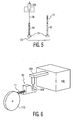
- Fig. 6 is a schematic view illustrating a feeder 10 according to the invention positioned adjacent a pick-and-place machine 100 having a pickup arm 102 from which a vacuum-operated pickup nozzle 104 is suspended.
- the arm 102 swings out from the machine, moves vertically downwards along a descending axis toward a component held in some fashion below the descending nozzle at a pickup location, engages and picks up by suction or other means the engaged component, and then returns to place the component on a computer-directed site on a PCB, after which a new cycle begins repeating the above steps.
- the function of the feeder 10 is to supply automatically a fresh component at the pickup location after the previous component has been picked up.
- the feeder of the invention is adapted for use with a variety of different pick-and-place machines supplied by different vendors.
- the machines typically have different operating cycles and thus, for maximum speed, it is desirable to be able to adjust the feeder operating cycle to be compatible with each of the different machines.
- the feeder uses a microcontroller which can be programmed to control the timing of the sequence of steps that the feeder employs to carry out its functions.
- the feeder is not physically actuated by the pick-and-place machine nor is it connected to the normal feeder actuating mechanisms of the machine.
- the only connecting relationships are optical sensors in the feeder for detecting the arrival of the pickup arm and the positioning of the feeder such that the pickup location is aligned with the descending axis of the pickup nozzle.
- Fig. 2 illustrates a strip 11 of SMT pincomponents 12 suspended from a common carrier 14 which are supplied from the reel 110 of Fig. 6.
- Each pin 12 comprises an elongated body having at its bottom a base 15 for surface mount on the PCB and having at its top where it is attached to the carrier a beveled end 16 (of reduced crosssection) which allows the pin to be readily separated from the carrier 14 by applying a pushing force transverse to the plane of the carrier.
- the carrier 14 is composed of connected segments 18, each with an indexing hole 19, connected to adjacent neighbors by a reduced crosssection link 20, which allows the segment 18 to be readily separated from the carrier 14 also by applying a pushing force transverse to the plane of the carrier.
- the vacuum nozzle 104 must pickup the pin by its beveled end 16 so that at the PCB it can be placed base-down 15 on the chosen site. Therefore, the pin 12 must be separated from the carrier 14 to free up its beveled end 16 before it can be picked up by the nozzle 104.
- Fig. 1 is a partial assembly view from the top of one form of feeder 10 according to the invention, which comprises a strip advancing means 20, a component-retaining means 40, and a component-separating means 60 mounted on a suitable support (not shown).
- Figs. 3-5 illustrate the basic operations of the machine.
- the strip 11 is shown advancing step-by-step in the direction of the arrow 9 by an indexing wheel 22 with protuberances 24 engaging the holes 19 in the strip segments 18.
- the strip is advanced until the lead pin 13 reaches a position opposite the pin separator and retainer 40, 60 which have been positioned as shown on the far side of the strip.
- far side is meant the side of the strip plane furthest from the pickup location; in Fig. 3, the side above the strip 11.
- near side is meant the side of the strip plane nearest the pickup location; in Fig. 3, the side below the strip 11.
- the parts 40, 60 on the far side of the strip move laterally (downward in Fig. 3) toward the pickup location during which the separator 60 engages the lead pin simultaneously with the pin retainer 40 shearing the lead pin 13 from the carrier and also shearing from the strip the scrap segment 17 left over when the previous pin was separated from that segment.
- the parts continue moving as shown by the vertical arrow 64 in Fig. 4 toward the pickup location and are now, as shown in Fig. 4, on the near side of the strip with the captured lead pin 13 held by the pin retainer 40.
- the lateral separation of the plane of the advancing strip 11 from the pickup location 25 is illustrated in the end view schematically shown in Fig. 5. As will be noted, the pickup location 25 is aligned with the descending axis 26 of the pickup nozzle 104.
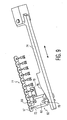
- Fig. 7 illustrates one form of advancing means suitable for use in the feeder of the invention. It uses mechanical and pneumatic means, but it will be understood that the required action can be achieved by other well known means such as electrical by any kind of timer or preferably under control of controller (not shown).
- the action required is simply to rotate a vertical drive shaft 26 under control of a mechanical linkage and ratcheting device 28 activated by the stroke of a pneumatic cylinder (not shown) whose piston is connected to a small pivoting block 30 by means of a pin.
- the lever 30 is moved to theright in Fig. 7, the vertical shaft 26 rotates CCW, which in turn rotates CCW the indexing wheel 22 mounted on top and thus the strip 11 is advanced to the right one pitch distance (the center-to-center spacing of the strip holes 19).
- Fig. 8 illustrates one form of the pin separator 60 and pin retainer 40 assembly of the invention.
- Figs. 9-13 illustrate various details of the assembly.
- the pin separator 60 comprises a block 62 mounted in any suitable way for movement along a path 64 that preferably is transverse to the plane of the strip 11.
- the path 64 is shown by the vertical arrow in Fig. 4 and by the double-headed arrow in Fig. 8.
- the separator comprises a shaft aligner 66 that is sized and positioned to engage the indexing hole 19 in the segment 18 supporting the lead pin 13 in order to precisely align that carrier segment with the pin separator.
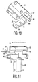
- the separator further comprises an upstream protrusion 68 positioned to engage the side of the lead pin, which includes an axially-extending upstream toothed member or comb 70 which also embraces the two preceding pins 12 leaving however a gap at the rear between the back surface of the tooth and the pins -to accommodate the lateral movement of the block 62 without the comb 70 contacting at its back surface the previous pins 12. This assists in maintaining the alignment of the strip pins with the pin separator.
- the separator further comprises a downstream protrusion 72 which functions to shear off the scrap segment 17 (not shown in this view) left over on the strip when the preceding pin was separated.
- Fig. 9 is a view from the rear of the pin separator 60. It also shows one way of actuating the pin separator, comprising a pneumatic cylinder (not shown) whose piston is connected to a lever 74 which is moved in the direction shown by the double-ended arrow. The end of the lever 74 forms a wedge cam 76 which drives a follower 78 connected to the block 62. The block 62 is held in position against the wedge cam by friction so that the lateral position of the cam surface 76 controls the lateral position of the block 62. As before, the cylinder is actuated by a suitable controller to function as will be described below in greater detail.
- the separator block 62 cooperates with a block 42 that forms part of the pin retainer 40.
- the separator block 62 has a descending extension 80 (Fig. 11) forming a pushing surface 82 that contacts a facing pushing surface 44 of the pin retainer block 42.
- the retainer block has a clamping surface 46 formed by vertically-spaced V-grooves separated by a recess 47 facing the far side of the strip, the same side as that of the pin separator.
- the geometry is such that, as the pin separator protrusion 68 acting as a punch engages the far side of the lead pin 13 close to its connection to the carrier, a lower portion of the same lead pin 13 is simultaneously engaged by the V-grooves of the clamping surface 46.
- a pin-retaining lever 84 (Figs.
- FIG. 12 shows schematically a conventional pneumatic cylinder 92 (shown schematically) whose piston when extended actuates a simple lever system which moves the spring-loaded lever 84 to its unclamping position. It also illustrates the spring 94 which maintains the clamping pressure.
- the mechanism so far described moves the pin retainer and separator from its pre-separation positions on the far side of the pin strip to where the separated pin 13 is aligned at the pickup location 25 with the descending axis 26 of the pickup nozzle, on the near side of the pin strip.
- the assembly must then be moved back to its pre-separation positions on the far side of the pin strip, illustrated in Fig. 8. This is accomplished, in one form, by the extractor linkage shown in Fig. 13.
- This comprises a pneumatic cylinder 96 whose piston is connected to an L-shaped linkage 98 rotatably mounted on a post 99 and which is slidingly coupled 100 to a mounting 102 for the block 42 of the pin retainer 40.
- the linkage 98 simply rotates to a new position. But when the cylinder 96 is activated, the extended piston rotates the linkage CCW pushing the pin retainer and the pin separator to which it is coupled back to their pre-separation positions on the far side of the pin strip.
- a first electronic sensor 120 integral to the feeder detects the presence of the nozzle and initiates a first release cycle including a preset time delay controlled by a PLC programmable logic controller 121 integral to the feeder so as to release the pin from its holding means when the nozzle has descended an appropriate distance onto the beveled pin end such that it then alone can support the pin.
- the significant features of this unusual procedure are (a) location of the strip of suspended pins in a plane laterally offset from the pickup location; (b) simultaneous engagement of the pin break-off member and the clamping surface with the far side of the lead pin; (c) lateral movement (advancement) of the component-retaining member with the separated lead pin together with the component-separating member from the offset plane of the strip toward the pickup location; (d) lateral movement (withdrawal) of the component-retaining member without the pin together with the component-separating member from the pickup location toward the offset plane of the strip to retrieve a new pin.
- This lateral withdrawal movement away from the pickup location after the vacuum nozzle 104 has engaged the pin is to restore the pre-separation positions of the two members, namely, both the component-retaining member 40 and the component-separating member 60 on the far (opposite) side of the carrier facing away from the pickup location, which is necessary to ensure that both the component-retaining member and the component-separating member will be clear of the advancing carrier strip containing the next following pin including the still-left-in-place downstream segment from which the lead pin was separated. Interference is also avoided by the return path extending below the carrier and pins.
- the PLC controller 121 is programmed so that the carrier is not advanced until after the pre-separating positions are attained as indicated by a fourth electronic sensor 136.
- the offset position of the strip of suspended pins is necessary because the pin must be released from the carrier supporting it by its beveled end from above to free its beveled end so that it can be engaged by the vacuum nozzle.
- the controller is programmed so that the time delay that occurs between the time that the first cylinder 92 is actuated to swing the spring-loaded lever 84 away from the pin to release it and the time that the V-block starts to withdraw from the pickup location is sufficient so that when the nozzle 104 rises with the captured pin, the pin voyage is not interfered with.
- the base 15 of the MiniFoot pins extends in several directions so care must be exercised that those extensions do not strike any feeder parts during their ascent The appropriate timing of these steps avoids that problem, and is easily controlled by the appropriate timing programmed into the controller, as those skilled in this art will readily appreciate.
- controllers allow the user to program numbers representing times into particular registers, and the controller as it executes its program knows to access certain registers to determine the timing of the outputting of control pulses from selected controller outputs connected to the different electronic valves described, which are also available commercially.
- other controllable devices such as electrical solenoids and others can also be substituted for the pneumatic actuating devices described.
- the use of this programmable controller thus makes it easy to customize the feeder to the particular pick-and-place machine used by the PCB maker.
- the electronic sensors employed can be of various known kinds.
- convergent optical sensors are employed which combine an LED as IR beam generator and a phototransistor as the beam detector.
- the first sensor which is of this kind, thus has its beam always ON being detected.
- the arrival of the nozzle interrupts the beam signaling its arrival.
- the detection of the beam signals its departure.
- Other kinds of sensors to perform the same functions can easily be substituted for that and the other sensors.
- the comb 70 added to the pin-separating block is the pins on the strip.
- the pins on the strip can on occasion become bent in the plane of the pin strip.
- the comb 70 shown in Fig. 10 which is integral with the pin separating device, serves the purpose of straightening pins which may be skewed (bent at the top point where they join the carrier strip) along the direction of travel of the carrier.
- the first comb pocket 69 is wider so as to start the straightening process with the angled sides of the teeth
- the second pocket 71 is much narrower and further functions to position the pin vertically
- the V block itself serves as the final means to ensure the pin is straight. This process works very well and is capable of straightening pins which are skewed as much as 30 degrees or more to the vertical to provide a high degree of consistent pin positioning.
Landscapes
- Engineering & Computer Science (AREA)
- Manufacturing & Machinery (AREA)
- Supply And Installment Of Electrical Components (AREA)
Applications Claiming Priority (2)
| Application Number | Priority Date | Filing Date | Title |
|---|---|---|---|
| US10/027,869 US6691859B2 (en) | 2001-12-20 | 2001-12-20 | Automatic feeder for strip-supported contacts |
| US27869 | 2001-12-20 |
Publications (3)
| Publication Number | Publication Date |
|---|---|
| EP1326488A2 true EP1326488A2 (de) | 2003-07-09 |
| EP1326488A3 EP1326488A3 (de) | 2005-08-10 |
| EP1326488B1 EP1326488B1 (de) | 2007-04-18 |
Family
ID=21840236
Family Applications (1)
| Application Number | Title | Priority Date | Filing Date |
|---|---|---|---|
| EP02028026A Expired - Lifetime EP1326488B1 (de) | 2001-12-20 | 2002-12-16 | Automatische Zufuhrvorrichtung für streifenweise angeordnete Kontaktelemente |
Country Status (4)
| Country | Link |
|---|---|
| US (2) | US6691859B2 (de) |
| EP (1) | EP1326488B1 (de) |
| JP (1) | JP2003198188A (de) |
| DE (1) | DE60219582T2 (de) |
Cited By (6)
| Publication number | Priority date | Publication date | Assignee | Title |
|---|---|---|---|---|
| US7003928B2 (en) | 2002-10-04 | 2006-02-28 | Jcs/Thg, Llc | Appliance for vacuum sealing food containers |
| US7076929B2 (en) | 2002-10-04 | 2006-07-18 | Jcs/Thg, Llc | Appliance for vacuum sealing food containers |
| US7131250B2 (en) | 2002-10-04 | 2006-11-07 | Jcs/Thg, Llp | Appliance for vacuum sealing food containers |
| WO2010043579A1 (en) * | 2008-10-13 | 2010-04-22 | Tyco Electronics Amp Gmbh | Device and method for automatically populating electrical components with contact elements |
| WO2012127021A1 (de) * | 2011-03-24 | 2012-09-27 | Continental Teves Ag & Co. Ohg | Verfahren und bestückungsvorrichtung zur herstellung eines elektrischen kontaktaufnehmerplättchens und zur automatisierten bestückung eines elektrischen oder elektronischen moduls mit dem kontaktaufnehmerplättchen, kontaktaufnehmerplättchen sowie verwendung des kontaktaufnehmerplättchens |
| WO2020108996A1 (de) * | 2018-11-29 | 2020-06-04 | Osram Opto Semiconductors Gmbh | Optoelektronisches halbleiterbauteil, trägerrolle mit solchen optoelektronischen halbleiterbauteilen und textilgewebe |
Families Citing this family (10)
| Publication number | Priority date | Publication date | Assignee | Title |
|---|---|---|---|---|
| JP4564235B2 (ja) * | 2003-02-24 | 2010-10-20 | パナソニック株式会社 | 部品実装装置及び部品実装方法 |
| EP2035157B1 (de) * | 2006-06-28 | 2017-09-06 | Monsanto Technology, LLC | System zur sortierung kleiner objekte |
| DE102008023621B4 (de) * | 2007-06-13 | 2014-02-13 | Asm Assembly Systems Gmbh & Co. Kg | Zuführvorrichtung zum Transportieren von Bauelementen und Bestückautomat |
| US8113402B2 (en) * | 2007-11-29 | 2012-02-14 | Tyco Electronics Corporation | Feed mechanism for a machine |
| CN102469757A (zh) * | 2010-11-17 | 2012-05-23 | 康准电子科技(昆山)有限公司 | 进料辅助装置 |
| JP6667213B2 (ja) * | 2014-07-16 | 2020-03-18 | キヤノン株式会社 | 光学走査装置、画像形成装置、及び光学走査装置の組み立て方法 |
| SG11201803624QA (en) * | 2015-11-02 | 2018-05-30 | Universal Instruments Corp | Media straightener, feeder and method |
| DE102016118153B4 (de) * | 2016-09-26 | 2018-10-04 | Trumpf Werkzeugmaschinen Gmbh + Co. Kg | Werkzeug und Verfahren zumindest zum Handhaben von Werkstücken |
| CN106684666A (zh) * | 2017-02-28 | 2017-05-17 | 东莞市翔烨电子设备有限公司 | 一种全自动剥皮焊接机及焊接方法 |
| CN107380667B (zh) * | 2017-08-28 | 2023-04-14 | 鹤壁海昌智能科技股份有限公司 | 一种储线机构 |
Family Cites Families (19)
| Publication number | Priority date | Publication date | Assignee | Title |
|---|---|---|---|---|
| NL8001114A (nl) * | 1980-02-25 | 1981-09-16 | Philips Nv | Inrichting voor de montage van aansluitdraadloze plaat- of blokvormige elektronische onderdelen op een substraat. |
| DE3150945A1 (de) * | 1981-12-23 | 1983-07-07 | Philips Patentverwaltung Gmbh, 2000 Hamburg | Vorrichtung zum ueberbringen von anschlussbeinlosen bauelementen auf eine vorgesehene setzposition einer schaltungsplatine |
| GB8406129D0 (en) * | 1984-03-08 | 1984-04-11 | Dyna Pert Precima Ltd | Orienting electrical components |
| US4586670A (en) * | 1984-12-17 | 1986-05-06 | Usm Corporation | Tape stripper for electrical component tape feeder |
| US4610083A (en) * | 1985-08-26 | 1986-09-09 | Zenith Electronics Corporation | Method and apparatus for electronic component matching |
| JPS62114289A (ja) * | 1985-11-14 | 1987-05-26 | 松下電器産業株式会社 | 電子部品の装着方法および装置 |
| US4872258A (en) * | 1988-09-22 | 1989-10-10 | Universal Instruments Corporation | Pick and place method and apparatus |
| US5017078A (en) * | 1990-01-24 | 1991-05-21 | Molex Incorporated | Method and apparatus for unloading components from tape carrier packaging |
| US5259500A (en) * | 1991-12-23 | 1993-11-09 | Joseph Alvite | Tape packaging system with removeable covers |
| US5312015A (en) * | 1992-04-03 | 1994-05-17 | Gpax International, Inc. | Gated-loop packaging system and manipulating apparatus |
| US5339939A (en) * | 1992-08-31 | 1994-08-23 | Cna Manufacturing Systems, Inc. | Pocket tape feeder system |
| US5397423A (en) * | 1993-05-28 | 1995-03-14 | Kulicke & Soffa Industries | Multi-head die bonding system |
| JPH06338700A (ja) * | 1993-05-31 | 1994-12-06 | Sony Corp | 実装装置 |
| US5605430A (en) * | 1994-02-15 | 1997-02-25 | Zierick Manufacturing Corporation | Feeder and method of supplying a continuous strip of surface mount contacts to surface mounting equipment |
| US5533253A (en) * | 1994-09-20 | 1996-07-09 | Sanyo Electric Co., Ltd. | Apparatus and method for mounting an air-core coil |
| US6082954A (en) * | 1997-02-21 | 2000-07-04 | Summit Holding Two, Inc. | Tape feeders and systems using the same |
| US6141869A (en) * | 1998-10-26 | 2000-11-07 | Silicon Bandwidth, Inc. | Apparatus for and method of manufacturing a semiconductor die carrier |
| JP4399088B2 (ja) * | 2000-06-01 | 2010-01-13 | 富士機械製造株式会社 | 電気部品装着装置 |
| US6631868B2 (en) * | 2000-12-14 | 2003-10-14 | Delaware Capital Formation, Inc. | Tape feeder with splicing capabilities |
-
2001
- 2001-12-20 US US10/027,869 patent/US6691859B2/en not_active Expired - Fee Related
-
2002
- 2002-05-17 US US10/147,398 patent/US6966738B1/en not_active Expired - Fee Related
- 2002-12-16 DE DE60219582T patent/DE60219582T2/de not_active Expired - Fee Related
- 2002-12-16 EP EP02028026A patent/EP1326488B1/de not_active Expired - Lifetime
- 2002-12-20 JP JP2002369499A patent/JP2003198188A/ja active Pending
Cited By (11)
| Publication number | Priority date | Publication date | Assignee | Title |
|---|---|---|---|---|
| US7003928B2 (en) | 2002-10-04 | 2006-02-28 | Jcs/Thg, Llc | Appliance for vacuum sealing food containers |
| US7076929B2 (en) | 2002-10-04 | 2006-07-18 | Jcs/Thg, Llc | Appliance for vacuum sealing food containers |
| US7131250B2 (en) | 2002-10-04 | 2006-11-07 | Jcs/Thg, Llp | Appliance for vacuum sealing food containers |
| US7231753B2 (en) | 2002-10-04 | 2007-06-19 | Sunbeam Products, Inc. | Appliance for vacuum sealing food containers |
| US7401452B2 (en) | 2002-10-04 | 2008-07-22 | Sunbeam Products, Inc. | Appliance for vacuum sealing food containers |
| US7454884B2 (en) | 2002-10-04 | 2008-11-25 | Sunbeam Products, Inc. | Appliance for vacuum sealing food containers |
| WO2010043579A1 (en) * | 2008-10-13 | 2010-04-22 | Tyco Electronics Amp Gmbh | Device and method for automatically populating electrical components with contact elements |
| WO2012127021A1 (de) * | 2011-03-24 | 2012-09-27 | Continental Teves Ag & Co. Ohg | Verfahren und bestückungsvorrichtung zur herstellung eines elektrischen kontaktaufnehmerplättchens und zur automatisierten bestückung eines elektrischen oder elektronischen moduls mit dem kontaktaufnehmerplättchen, kontaktaufnehmerplättchen sowie verwendung des kontaktaufnehmerplättchens |
| CN103548428A (zh) * | 2011-03-24 | 2014-01-29 | 大陆-特韦斯贸易合伙股份公司及两合公司 | 用于制造电触点接纳板和用于自动化地给电模块或电子模块装配触点接纳板的方法和装配装置、触点接纳板及该触点接纳板的应用 |
| CN103548428B (zh) * | 2011-03-24 | 2017-06-13 | 大陆-特韦斯贸易合伙股份公司及两合公司 | 用于制造电触点接纳板和用于自动化地给电模块或电子模块装配触点接纳板的方法和装配装置、触点接纳板及该触点接纳板的应用 |
| WO2020108996A1 (de) * | 2018-11-29 | 2020-06-04 | Osram Opto Semiconductors Gmbh | Optoelektronisches halbleiterbauteil, trägerrolle mit solchen optoelektronischen halbleiterbauteilen und textilgewebe |
Also Published As
| Publication number | Publication date |
|---|---|
| EP1326488A3 (de) | 2005-08-10 |
| HK1056814A1 (en) | 2004-02-27 |
| US6691859B2 (en) | 2004-02-17 |
| US6966738B1 (en) | 2005-11-22 |
| DE60219582D1 (de) | 2007-05-31 |
| DE60219582T2 (de) | 2007-12-27 |
| JP2003198188A (ja) | 2003-07-11 |
| US20030118429A1 (en) | 2003-06-26 |
| EP1326488B1 (de) | 2007-04-18 |
Similar Documents
| Publication | Publication Date | Title |
|---|---|---|
| EP1326488B1 (de) | Automatische Zufuhrvorrichtung für streifenweise angeordnete Kontaktelemente | |
| US4819699A (en) | Cartridge feed system for automatic PCB loading machine | |
| CA1127775A (en) | Component inserting apparatus | |
| KR100341290B1 (ko) | 부품실장기 | |
| EP0633826A4 (de) | Modulare stanzstation und verfahren zur anwendung. | |
| EP1793660A1 (de) | Vorrichtung zur Montage von elektronischen Bauteilen | |
| CN106465578B (zh) | 元件安装装置 | |
| JP3771310B2 (ja) | フィーダー装置 | |
| JP3781799B2 (ja) | 表面実装端子の連続ストリップをピックアンドプレース機械に供給するフィーダおよび供給方法。 | |
| JP3546223B2 (ja) | コネクタ組立機 | |
| HK1056814B (en) | Automatic feeder for strip-supported contacts | |
| US4748741A (en) | Pin insertion apparatus and method of inserting pins | |
| JP2001322715A (ja) | ワーク搬送装置 | |
| JP3889774B2 (ja) | フィーダー | |
| JP2020064906A (ja) | 部品装着装置、及び、部品装着方法 | |
| JP3733488B2 (ja) | 横型チップ電子部品の製造方法及び装置 | |
| JPH0777303B2 (ja) | 電子部品供給装置 | |
| JPH0112390Y2 (de) | ||
| JPH03268487A (ja) | 部品装着装置 | |
| JPH0554218B2 (de) | ||
| JP2008108777A (ja) | 電子部品の供給装置及び方法 | |
| JPH0412933A (ja) | 部品供給装置 | |
| JPH04143040A (ja) | クラッド母材の搬送装置 | |
| JPH0745994A (ja) | テープフィーダ | |
| JPH071647B2 (ja) | 電線識別片自動取付装置 |
Legal Events
| Date | Code | Title | Description |
|---|---|---|---|
| PUAI | Public reference made under article 153(3) epc to a published international application that has entered the european phase |
Free format text: ORIGINAL CODE: 0009012 |
|
| AK | Designated contracting states |
Designated state(s): AT BE BG CH CY CZ DE DK EE ES FI FR GB GR IE IT LI LU MC NL PT SE SI SK TR |
|
| AX | Request for extension of the european patent |
Extension state: AL LT LV MK RO |
|
| PUAL | Search report despatched |
Free format text: ORIGINAL CODE: 0009013 |
|
| AK | Designated contracting states |
Kind code of ref document: A3 Designated state(s): AT BE BG CH CY CZ DE DK EE ES FI FR GB GR IE IT LI LU MC NL PT SE SI SK TR |
|
| AX | Request for extension of the european patent |
Extension state: AL LT LV MK RO |
|
| RIC1 | Information provided on ipc code assigned before grant |
Ipc: 7H 05K 13/04 A Ipc: 7H 01R 43/20 B |
|
| 17P | Request for examination filed |
Effective date: 20060201 |
|
| AKX | Designation fees paid |
Designated state(s): DE FR GB IT |
|
| GRAP | Despatch of communication of intention to grant a patent |
Free format text: ORIGINAL CODE: EPIDOSNIGR1 |
|
| GRAS | Grant fee paid |
Free format text: ORIGINAL CODE: EPIDOSNIGR3 |
|
| GRAA | (expected) grant |
Free format text: ORIGINAL CODE: 0009210 |
|
| AK | Designated contracting states |
Kind code of ref document: B1 Designated state(s): DE FR GB IT |
|
| REF | Corresponds to: |
Ref document number: 60219582 Country of ref document: DE Date of ref document: 20070531 Kind code of ref document: P |
|
| REG | Reference to a national code |
Ref country code: HK Ref legal event code: GR Ref document number: 1056814 Country of ref document: HK |
|
| EN | Fr: translation not filed | ||
| PLBE | No opposition filed within time limit |
Free format text: ORIGINAL CODE: 0009261 |
|
| STAA | Information on the status of an ep patent application or granted ep patent |
Free format text: STATUS: NO OPPOSITION FILED WITHIN TIME LIMIT |
|
| 26N | No opposition filed |
Effective date: 20080121 |
|
| PG25 | Lapsed in a contracting state [announced via postgrant information from national office to epo] |
Ref country code: IT Free format text: LAPSE BECAUSE OF FAILURE TO SUBMIT A TRANSLATION OF THE DESCRIPTION OR TO PAY THE FEE WITHIN THE PRESCRIBED TIME-LIMIT Effective date: 20070418 Ref country code: FR Free format text: LAPSE BECAUSE OF FAILURE TO SUBMIT A TRANSLATION OF THE DESCRIPTION OR TO PAY THE FEE WITHIN THE PRESCRIBED TIME-LIMIT Effective date: 20071214 |
|
| PGFP | Annual fee paid to national office [announced via postgrant information from national office to epo] |
Ref country code: DE Payment date: 20080130 Year of fee payment: 6 Ref country code: GB Payment date: 20080130 Year of fee payment: 6 |
|
| PG25 | Lapsed in a contracting state [announced via postgrant information from national office to epo] |
Ref country code: FR Free format text: LAPSE BECAUSE OF FAILURE TO SUBMIT A TRANSLATION OF THE DESCRIPTION OR TO PAY THE FEE WITHIN THE PRESCRIBED TIME-LIMIT Effective date: 20070418 |
|
| GBPC | Gb: european patent ceased through non-payment of renewal fee |
Effective date: 20081216 |
|
| PG25 | Lapsed in a contracting state [announced via postgrant information from national office to epo] |
Ref country code: DE Free format text: LAPSE BECAUSE OF NON-PAYMENT OF DUE FEES Effective date: 20090701 |
|
| PG25 | Lapsed in a contracting state [announced via postgrant information from national office to epo] |
Ref country code: GB Free format text: LAPSE BECAUSE OF NON-PAYMENT OF DUE FEES Effective date: 20081216 |