EP1327140B1 - Verfahren und vorrichtung zur austenitischen schweissnahtkontrolle mit hilfe von ultraschall - Google Patents
Verfahren und vorrichtung zur austenitischen schweissnahtkontrolle mit hilfe von ultraschall Download PDFInfo
- Publication number
- EP1327140B1 EP1327140B1 EP01977640A EP01977640A EP1327140B1 EP 1327140 B1 EP1327140 B1 EP 1327140B1 EP 01977640 A EP01977640 A EP 01977640A EP 01977640 A EP01977640 A EP 01977640A EP 1327140 B1 EP1327140 B1 EP 1327140B1
- Authority
- EP
- European Patent Office
- Prior art keywords
- transducer
- weld
- transducers
- sound
- weld seam
- Prior art date
- Legal status (The legal status is an assumption and is not a legal conclusion. Google has not performed a legal analysis and makes no representation as to the accuracy of the status listed.)
- Expired - Lifetime
Links
- 238000007689 inspection Methods 0.000 title claims description 48
- 238000000034 method Methods 0.000 title claims description 21
- 239000002184 metal Substances 0.000 claims description 30
- 229910052751 metal Inorganic materials 0.000 claims description 30
- 238000012360 testing method Methods 0.000 claims description 23
- 239000000463 material Substances 0.000 claims description 11
- 230000004927 fusion Effects 0.000 claims description 7
- 230000035945 sensitivity Effects 0.000 claims description 5
- 238000012216 screening Methods 0.000 claims description 3
- 229910000831 Steel Inorganic materials 0.000 description 5
- 239000010959 steel Substances 0.000 description 5
- PXHVJJICTQNCMI-UHFFFAOYSA-N Nickel Chemical compound [Ni] PXHVJJICTQNCMI-UHFFFAOYSA-N 0.000 description 4
- 238000003491 array Methods 0.000 description 3
- 230000007547 defect Effects 0.000 description 3
- 229910052759 nickel Inorganic materials 0.000 description 2
- 239000000523 sample Substances 0.000 description 2
- 239000010953 base metal Substances 0.000 description 1
- 239000013078 crystal Substances 0.000 description 1
- 238000013480 data collection Methods 0.000 description 1
- 230000001066 destructive effect Effects 0.000 description 1
- 239000003949 liquefied natural gas Substances 0.000 description 1
- 239000007788 liquid Substances 0.000 description 1
- 230000005855 radiation Effects 0.000 description 1
- 238000012552 review Methods 0.000 description 1
- 238000005096 rolling process Methods 0.000 description 1
- 238000003466 welding Methods 0.000 description 1
Images



Classifications
-
- G—PHYSICS
- G01—MEASURING; TESTING
- G01N—INVESTIGATING OR ANALYSING MATERIALS BY DETERMINING THEIR CHEMICAL OR PHYSICAL PROPERTIES
- G01N29/00—Investigating or analysing materials by the use of ultrasonic, sonic or infrasonic waves; Visualisation of the interior of objects by transmitting ultrasonic or sonic waves through the object
-
- G—PHYSICS
- G01—MEASURING; TESTING
- G01N—INVESTIGATING OR ANALYSING MATERIALS BY DETERMINING THEIR CHEMICAL OR PHYSICAL PROPERTIES
- G01N29/00—Investigating or analysing materials by the use of ultrasonic, sonic or infrasonic waves; Visualisation of the interior of objects by transmitting ultrasonic or sonic waves through the object
- G01N29/36—Detecting the response signal, e.g. electronic circuits specially adapted therefor
- G01N29/40—Detecting the response signal, e.g. electronic circuits specially adapted therefor by amplitude filtering, e.g. by applying a threshold or by gain control
-
- G—PHYSICS
- G01—MEASURING; TESTING
- G01N—INVESTIGATING OR ANALYSING MATERIALS BY DETERMINING THEIR CHEMICAL OR PHYSICAL PROPERTIES
- G01N29/00—Investigating or analysing materials by the use of ultrasonic, sonic or infrasonic waves; Visualisation of the interior of objects by transmitting ultrasonic or sonic waves through the object
- G01N29/04—Analysing solids
- G01N29/11—Analysing solids by measuring attenuation of acoustic waves
-
- G—PHYSICS
- G01—MEASURING; TESTING
- G01N—INVESTIGATING OR ANALYSING MATERIALS BY DETERMINING THEIR CHEMICAL OR PHYSICAL PROPERTIES
- G01N29/00—Investigating or analysing materials by the use of ultrasonic, sonic or infrasonic waves; Visualisation of the interior of objects by transmitting ultrasonic or sonic waves through the object
- G01N29/36—Detecting the response signal, e.g. electronic circuits specially adapted therefor
- G01N29/38—Detecting the response signal, e.g. electronic circuits specially adapted therefor by time filtering, e.g. using time gates
-
- G—PHYSICS
- G01—MEASURING; TESTING
- G01N—INVESTIGATING OR ANALYSING MATERIALS BY DETERMINING THEIR CHEMICAL OR PHYSICAL PROPERTIES
- G01N2291/00—Indexing codes associated with group G01N29/00
- G01N2291/01—Indexing codes associated with the measuring variable
- G01N2291/015—Attenuation, scattering
-
- G—PHYSICS
- G01—MEASURING; TESTING
- G01N—INVESTIGATING OR ANALYSING MATERIALS BY DETERMINING THEIR CHEMICAL OR PHYSICAL PROPERTIES
- G01N2291/00—Indexing codes associated with group G01N29/00
- G01N2291/02—Indexing codes associated with the analysed material
- G01N2291/023—Solids
- G01N2291/0234—Metals, e.g. steel
-
- G—PHYSICS
- G01—MEASURING; TESTING
- G01N—INVESTIGATING OR ANALYSING MATERIALS BY DETERMINING THEIR CHEMICAL OR PHYSICAL PROPERTIES
- G01N2291/00—Indexing codes associated with group G01N29/00
- G01N2291/02—Indexing codes associated with the analysed material
- G01N2291/028—Material parameters
- G01N2291/02854—Length, thickness
-
- G—PHYSICS
- G01—MEASURING; TESTING
- G01N—INVESTIGATING OR ANALYSING MATERIALS BY DETERMINING THEIR CHEMICAL OR PHYSICAL PROPERTIES
- G01N2291/00—Indexing codes associated with group G01N29/00
- G01N2291/04—Wave modes and trajectories
- G01N2291/042—Wave modes
- G01N2291/0421—Longitudinal waves
-
- G—PHYSICS
- G01—MEASURING; TESTING
- G01N—INVESTIGATING OR ANALYSING MATERIALS BY DETERMINING THEIR CHEMICAL OR PHYSICAL PROPERTIES
- G01N2291/00—Indexing codes associated with group G01N29/00
- G01N2291/04—Wave modes and trajectories
- G01N2291/042—Wave modes
- G01N2291/0422—Shear waves, transverse waves, horizontally polarised waves
-
- G—PHYSICS
- G01—MEASURING; TESTING
- G01N—INVESTIGATING OR ANALYSING MATERIALS BY DETERMINING THEIR CHEMICAL OR PHYSICAL PROPERTIES
- G01N2291/00—Indexing codes associated with group G01N29/00
- G01N2291/04—Wave modes and trajectories
- G01N2291/044—Internal reflections (echoes), e.g. on walls or defects
-
- G—PHYSICS
- G01—MEASURING; TESTING
- G01N—INVESTIGATING OR ANALYSING MATERIALS BY DETERMINING THEIR CHEMICAL OR PHYSICAL PROPERTIES
- G01N2291/00—Indexing codes associated with group G01N29/00
- G01N2291/10—Number of transducers
- G01N2291/106—Number of transducers one or more transducer arrays
-
- G—PHYSICS
- G01—MEASURING; TESTING
- G01N—INVESTIGATING OR ANALYSING MATERIALS BY DETERMINING THEIR CHEMICAL OR PHYSICAL PROPERTIES
- G01N2291/00—Indexing codes associated with group G01N29/00
- G01N2291/26—Scanned objects
- G01N2291/267—Welds
- G01N2291/2675—Seam, butt welding
Definitions
- This invention relates to the inspection of weld seams, and more particularly to the ultrasonic inspection of weld seams in structures.
- structure it is common for structural plates to be joined by welded seams.
- the welds can be made not only with ordinary ferritic steel, but also with metal that is high in nickel content.
- Ordinary ferritic steel weld material solidifies in a relatively uniform structure.
- Weld metal that is high in nickel content solidifies in a face-centered cubic (austenitic) crystal structure that typically has an elongated (dendritic) grain structure.
- UT ultrasonic testing
- Arrays of single-element transducers have been mounted on rolling carts that travel along a ferritic steel weld (commonly pipeline girth welds).
- the transducers are tied to computerized data collection systems that allow quick inspection of the seams.
- US 5,677,490 and EP 1 043 584 disclose UT testing devices that can be used for ordinary ferritic steel welds.
- Tanks for the storage of cryogenic liquids such as liquefied natural gas, for example are field-constructed from plates joined by austenitic butt welds that require 100% inspection for weld defects. Such welds have been conventionally inspected with photographic film exposed by dangerous levels of radiation. Such radiographic inspection is a potential safety hazard and a time-consuming step that sometimes controls the erection schedule of such tanks.
- a new method according to claim 1 for easily configuring a useful array of dual-element transducers for automated ultrasonic inspection of austenitic weld seams has been developed.
- the apparatus according to claim 11 comprising the new arrays facilitates ultrasonic inspection of austenitic weld seams, making it an attractive alternative to radiographic inspection.
- transducer positions and sound paths are laid out on the schematic, and it is then divided into at least two inspection zones.
- Transducer housing size and sound paths are selected for each inspection zone, and the maximum and minimum sound path distances from the transducer positions to the boundaries of the heat-affected zones are measured. Focal spot distances are selected that provide adequate sensitivity at both the minimum and the maximum sound path distances. Transducer standoff distances and gate settings are established from the schematic. Test plates are then used to determine transducer gain settings and to confirm adequate width-of-field. The transducers are then mounted on a carriage and used to inspect a test weld seam.
- the processor is programmed to analyze the signals from that transducer as though they were signals from two separate transducers.
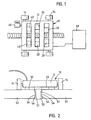
- Figs. 1 and 2 illustrate one embodiment of a carriage 10 that can be effectively used for automated, ultrasonic inspection of an austenitic weld seam.
- the carriage that has been illustrated includes a frame 12, magnetic wheels 14, and a creep wave transducer 20, an intermediate-zone transducer 30, and a lower-zone transducer 40.
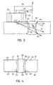
- the carriage rides over the length of a weld seam, as seen in fig. 2 .
- the weld seam is greater than 16 mm thick, and includes weld metal 50 that joins a pair of plates 52.
- Each plate includes a heat-affected zone 54 that extends from a fusion line 51 between the weld metal and the plates to a boundary 56 within the plate.
- the creep wave transducer 20 is configured to emit a sound along an upper sound path 22 to an upper portion 24 of the weld metal 50 and heat-affected zones 54.
- the creep wave transducer has a 40 x 40 mm housing, a 33 mm standoff distance 26 from the centerline of the weld to be inspected, and a frequency of 2 to 4 MHz.
- Other transducers could also be used to inspect the upper portion of the weld metal and heat-affected zones, but use ot a creep wave transducer is preferred.
- the intermediate-zone transducer 30 is configured to emit a sound along an intermediate sound path 32 to an intermediate portion 34 of the weld metal 50 and heat-affected zones 54.
- the intermediate-zone transducer is a dual-element, 70° longitudinal wave (L-wave) transducer that has a 40 x 40 mm housing, a 44 mm standoff distance 36 from the centerline of the weld to be inspected, and a frequency of 2 to 4 MHz.
- Other transducers could also be used to inspect the intermediate portion.
- the lower-zone transducer 40 (not seen) is configured to emit a sound along a lower sound path 42 to a lower portion 44 of the weld metal 50 and heat-affected zones 54.
- the lower-zone transducer is a dual-element, 60° L-wave transducer that has a 40 x 40 mm housing, a 40 mm standoff distance 46 from the centerline of the weld to be inspected, and a frequency of 2 to 4 MHz.
- Other transducers could also be used to inspect the lower portion.
- the illustrated carriage also includes a position encoder 60 that monitors the position of the carriage as it travels along the length of the weld seam.
- the transducers 20, 30, and 40 are connected to a computer 68 that is programed with one set of gain (sensitivity) and gate settings for obtaining and analyzing direct reflections of the sound transmitted by the transducers, and a second set of gain and gate settings for obtaining and analyzing any indirect reflections of the sound transmitted by the intermediate-zone transducer 30 along the intermediate sound path 32.
- the intermediate-zone transducer has gate settings for a 35 mm start and 25 mm length for obtaining and analyzing direct reflections of the sound from the intermediate transducer, and gate settings for a 56 mm start and 20 mm length for obtaining and analyzing indirect reflections of that sound.
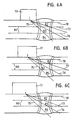
- a carriage like the one seen in figures 1-3 can be configured by a relatively simple, innovative method.
- a schematic of a section through the weld is then prepared.
- An example of such a schematic is seen in fig. 4 .
- the illustrated section is perpendicular to the centerline axis of the weld.
- the schematic includes representations of the fusion lines 51 between the weld metal 50 and the plates 52, the boundaries 56 of the heat-affected zones 54 in the plates, surface profiles 58 of the weld metal 50, and upper and lower surfaces 61, 62 of the plates 52.
- the representations need only be approximations of the actual features found in the weld metal and plates to be inspected, but it is preferred that the approximations be relatively accurate.
- Transducer positions and potential transducer sound paths for the transducer positions are then laid-out on the schematic.
- three separate copies of the schematic are used to show transducer positions and sound paths for three different standard transducers 70, 71, and 72 commonly available in the marketplace.
- a 45° sound path 75, a 60° sound path 76, a 70° sound path 77, and a creep-wave sound path 78 are shown.
- the weld metal 50 and heat-affected zones 54 on the schematic are divided into at least two inspection zones.
- horizontal dividing lines 80 have been added to the schematics of fig. 5 to divide the weld metal and heat-affected zones of the schematics into three zones of equal width: an upper inspection zone 82, an intermediate inspection zone 83, and a lower inspection zone 84.
- the dividing lines need not be perfectly horizontal, or even straight, and the zones need not be of equal width.
- each zone represents a maximum of approximately 8-10 mm of thickness of the actual weld metal and heat-affected zones, so for plates having a thickness of less than about 16 mm, the schematic of the weld metal and heat-affected zones need only be divided into two inspection zones, and for plates having a thickness of more than about 32 mm, the schematic would be divided into at least four inspection zones.
- a transducer is then selected to inspect each inspection zone.
- a housing size and sound path angle are each specified.
- Review of fig. 6 could lead, for example, to the selection of a 40 x 40 mm creep-wave transducer for the upper inspection zone 82, a 40 x 40 mm, 70° L-wave transducer for the intermediate inspection zone 83, and a 40 x 40 mm, 60° L-wave transducer for the lower inspection zone 84. It is generally preferable to use a creep-wave transducer for the upper inspection zone. As seen in fig.
- sound paths 22, 32, and 42 are drawn at transducer sound path angles ⁇ , ⁇ , and ⁇ so that they pass through the respective inspection zones.
- the points where the sound paths intersect the top surface 61 of the plates defme transducer positions 63, 64, and 65. It is preferred, but not essential, that the drawn sound path for each zone will cross the boundary 56 of each of the heat-affected zones 54 within that inspection zone.
- the drawn sound path 42 for the lower inspection zone 84 does not cross the boundary 56 for the heat-affected zone within the lower inspection zone. However, the drawn line only represents the centerline of the sound path. Because the sound from the transducer actually covers a broader area, it is sufficient that the drawn lines are in close proximity.
- transducer housing sizes are selected so that the transducers will not come into contact with the weld metal 50 as the weld is inspected.
- Setting housing sizes and standoff distances 26, 36, 46 in this way obviates the need to smooth the weld seam before inspection.
- a focal spot distance is determined for each transducer.
- a minimum and maximum sound path distance is measured from the transducer positions 63, 64, and 65 where the sound paths intersect the top surface of the plates to inspection limits 90 for each transducer's inspection zone.
- the inspection limits are located where the sound path from that transducer position intersects the boundaries of the heat-affected zones 54. Alternatively, the inspection limits might be placed at the points where the sound path enters the inspection zone, or at some intermediate or similar point.
- the minimum and maximum sound path distances for the creep-wave transducer 20, the intermediate-zone transducer 30, and the lower-zone transducer 40 are 16 mm and 47 mm, 35 5 mm and 60 mm, and 36 mm and 60 mm, respectively.
- a focal spot distance is then selected that will provide adequate sensitivity at both the maximum sound path distance and the minimum sound path distance for that transducer.
- assuring adequate sensitivity is done by selecting a focal spot distance that is at least one-half of the maximum sound path distance, and no more than twice the minimum sound path distance.
- the focal spots for the creep-wave transducer, the intermediate-zone transducer, and the lower-zone transducer are between 24 mm and 32 mm, 30 mm and 70 mm, and 30 mm and 72 mm, respectively.
- Standoff distances for each transducer may be measured directly from the schematic. In fig. 7 , standoff distances 26, 36, and 46 are measured from the centerline of the weld metal 50 to the transducer positions 63, 64, and 65. Other reference distances could also be used.
- the standoff distances for the illustrated creep-wave transducer 20, the intermediate-zone transducer 30, and the lower-zone transducer 40 are 33 mm, 44 mm, and 40 mm, respectively.
- Gate settings are then selected for each transducer.
- Gate settings may also be set for indirectly-reflected signals from one or more of the transducers.
- a "round-trip" sound path distance is determined using the distances of three legs: a first leg 91 from the transducer position 64 along the sound path 32 to a first reflecting position 92 at the centerline of the weld metal 50, a second leg 93 from the first reflecting position to a mode-converting position 94 on the lower surface of one of the plates 52, and a third leg 95 from the mode-converting position back to the transducer position.
- the third leg has been drawn at an angle of approximately 32°, because the illustrated 70° L-wave transducer is particularly sensitive to shear waves reaching it at that angle.
- the first reflecting position could be set at other points along the first leg. Preferably, however, it falls within the weld metal or at least one of the heat-affected zones.
- the length of the third leg should be multiplied by an appropriate multiplier to account for the different speed of travel of the mode-converted shear-wave leg 95.
- the actual distances of the legs 91, 93 and 95 are 40 mm, 26 mm, and 36 mm, respectively. Multiplying the length of the third leg by 1.8 provides a total round-trip effective distance of 131 mm. The round-trip effective distance is halved to provide an effective direct distance of 66 mm for indirectly-reflected signals.
- the start gate setting for obtaining such indirectly-reflected signals by reducing this round-trip effective distance by approximately 10 mm (or approximately half the width of the weld metal and heat-affected zones) to effectively cover the area of interest for the illustrated embodiment. In the illustrated embodiment, this results in a start gate setting of 56 mm for an indirectly-reflected sound from the transducer.
- the length gate setting for the indirectly-reflected signal is preferably derived by doubling the 10 mm distance. Consequently, in fig. 8 , the length gate setting for an indirectly-reflected signal from the transducer is 20 mm.
- Suitable gain settings for each transducer can be determined by using test plates, such as those seen in fig. 9 .
- the test plates 52' that are seen in fig. 9 are made from materials that are similar to the materials in the weld seam to be screened and have a geometry that is similar to the geometry of the weld seam to be screened (that is, the test plates are similar in thickness and material to the plates in the weld to be screened, have similar test weld metal 50', and have fusion lines 51' and boundaries 56' of the heat-affect zones 54' that are similar in contour to the fusion lines and boundaries in the weld to be screened). It is also preferred that the test plates include machined reference reflectors in the test weld. In fig.
- the reflectors include side-drilled holes 102, 103, and 104.
- a sample of each selected transducer is placed at an appropriate distance from the test weld metal so that its sound path is directed toward the side-drilled hole in its respective inspection zone.
- the lower zone transducer 40 is positioned so that its sound path 42 is directed toward the side-drilled hole 104 in the lower inspection zone 44'.
- this transducer should detect not only the side-drilled hole 104 in the lower inspection zone, but also the side-drilled hole 103 in the intermediate inspection zone 34'.
- each transducer gain setting is set so that the signal that is obtained on the computer 68 reaches 80% of the full- screen height for all transducer paths.
- the same gain setting minus 6dB can be generally used for the gain setting for indirectly-reflected signals.
- the carriage seen in fig. 1 can be assembled.
- the selected transducers 20, 30, and 40 are mounted at their respective standoff distances 26, 36, and 46, as seen in fig. 1 .
- Matching transducers are preferably mounted on the opposite side of the carriage, to improve the reliablity of the screening results.
- Appropriate software is set up to collect, analyze, and display data received from the transducers as a weld is inspected.
- the software it is useful to connect one or more of the transducers on multiple channels, one channel with gain and gate settings for obtaining and analyzing directly-reflected sounds from the transducer and the other channel with gain and gate settings for obtaining and analyzing indirectly-reflected sounds from the transducer.
- test weld seam should be made from materials that are similar to the materials in the weld seam to be screened, and should have a geometry that is similar to the geometry of the weld seam to be screened. It should also have artificial flaws, such as side-drilled holes 105, EDM notches 107, or welder-manipulated flaws 109.
- the threshold is set at 60% of the full screen height of the display.
Landscapes
- Physics & Mathematics (AREA)
- Biochemistry (AREA)
- Health & Medical Sciences (AREA)
- Life Sciences & Earth Sciences (AREA)
- Chemical & Material Sciences (AREA)
- Analytical Chemistry (AREA)
- General Health & Medical Sciences (AREA)
- General Physics & Mathematics (AREA)
- Immunology (AREA)
- Pathology (AREA)
- Acoustics & Sound (AREA)
- Investigating Or Analyzing Materials By The Use Of Ultrasonic Waves (AREA)
- Investigating And Analyzing Materials By Characteristic Methods (AREA)
Claims (14)
- Verfahren zum Gestalten einer Feldanordnung von Wandlern (Transducern) (20, 30, 40) in einer Ultraschalltestvorrichtung zum Prüfen auf Fehler im Volumen einer Schweißnaht (50), die aus einem austenitischen Material hergestellt ist und ein Paar von Schmelzlinien (51) aufweist, an denen sich das Schweißmaterial mit einem Paar von Blechen (52) verbindet, wobei das Verfahren die Schritte aufweist:(a) Erstellen eines Schemas eines Schnitts durch die Schweißnaht, die lotrecht zur Mittenachse der Schweißnaht (50) ist, wobei das Schema Darstellungen der Schmelzlinien (51), der Grenzen (56) der von der Wärme betroffenen Zonen in den Blechen (52), Oberflächenprofile des Schweißmetalls und die Ober- und Unterseiten (61, 62) der Bleche enthält;(b) Anordnen auf dem Schema von Wandlerpositionen und wenigstens einen möglichen Wandlerschallpfad;(c) Unterteilen des Schemas der Schweißnaht (50) in wenigstens zwei Untersuchungszonen (82, 83, 84);(d) Auswahl einer Wandlergröße und eines Schallpfadwinkels für jede Untersuchungszone (82, 83, 84);(e) Messen eines maximalen Schallpfadabstands und eines minimalen Schallpfadabstands von jeder Wandlerposition zu Untersuchungsgrenzen für die entsprechende Untersuchungszone des Wandlers (82, 83, 84);(f) Auswählen eines Brennfleckabstands für jeden Wandler (20, 30, 40), der eine angemessene Sensitivität sowohl beim maximalen Schallpfadabstand wie auch beim minimalen Schallpfadabstand bietet;(g) Bestimmen eines Wandler-Abstands für jeden Wandler (20, 30, 40);(g) Bestimmen von Gate-(Empfangs-)Einstellungen für jeden Wandler (20, 30, 40);(i) Bereitstellen von Testblechen (52'), die aus Materialien gefertigt sind, die ähnlich zu den zu prüfenden Materialien in der Schweißnaht (50) sind, eine Geometrie aufweisen, die ähnlich der Geometrie der zu untersuchenden Schweißnaht (50) ist, und maschinell hergestellte Referenzreflektoren im Schweißmetall haben;(j) Verwenden der Testbleche (52') zur Bestimmung einer Wandler-Gain-(Sende-)Einstellung für jeden Wandler (20, 30, 40);(k) Verwenden der Testbleche (52') zur Bestimmung einer angemessenen Feldbreite für jeden Wandler (20, 30, 40);(l) Befestigen der Wandler (20, 30, 40) an den Abständen auf einem Wagen (10), der sich entlang der Länge der Schweißnaht bewegen kann;(m) Bereitstellen von Testschweißnähten (50), die aus Materialien gefertigt sind, die ähnlich zu den Materialien in der zu prüfenden Schweißnaht (50) sind, eine Geometrie aufweisen, die ähnlich zu der Geometrie der zu prüfenden Schweißnaht (50) ist, und künstliche Fehler (105, 107, 109) aufweisen und(n) Verwenden des Wagens (10), um die Testschweißnähte zu untersuchen.
- Verfahren gemäß Anspruch 1, wobei die Untersuchungszonen (82, S3, 84) gleich breit sind.
- Verfahren gemäß Anspruch 1, wobei die Bleche (52) wenigstens 16 mm dick sind und eine dazwischenliegende Untersuchungszone (83) auf dem Schema der Schweißnaht angeordnet ist.
- Verfahren gemäß Anspruch 1, wobei die Gate-Einstellungen bestimmt werden, um den direkt reflektierten Schall zu empfangen, und weitere Gate-Einstellungen bestimmt werden, um indirekt reflektierten Schall von einem der Wandler (20, 30, 40) aufzunehmen.
- Verfahren gemäß Anspruch 1, wobei die Gain-Einstellungen des Wandleres bestimmt werden, um den direkt reflektierten Schall zu empfangen, und weitere Gain-Einstellungen bestimmt werden, um indirekt reflektierten Schall von einem der Wandler (20, 30, 40) zu empfangen.
- Verfahren gemäß Anspruch 1, wobei ein Creep-Wave-(Kriechwellen-)Wandler (20) zur Untersuchung eines oberen Bereichs (24) der Schweißnaht verwendet wird.
- Verfahren gemäß Anspruch 1, wobei wenigstens einer der Wandler ein Longitudionalwellen-Wandler (40) ist, der eine Frequenz von 2 bis 4 MHz besitzt.
- Verfahren gemäß Anspruch 1, wobei einer der Wandler (40) zur Untersuchung eines unteren Bereichs (44) der Schweißnaht ausgewählt wird;
zwei Gruppen von Gate-Einstellungen für diesen Wandler (40) des unteren Bereichs ausgewählt werden, eine Gruppe für den indirekt reflektierten Schall und die andere Gruppe für den direkt reflektierten Schall vom gleichen Wandler;
zwei Wandler-Gain-Einstellungen, die für den Wandler des unteren Bereichs ausgewählt werden, eine Gain-Einstellung für den indirekt reflektierten Schall und die andere Gain-Einstellung für den direkt reflektierten Schall;
die Wandler (20, 40) auf einem Wagen (10) befestigt sind, der sich entlang der Länge der Schweißnaht bewegen kann; und ein Prozessor (68) programmiert ist, um die Signale von dem Wandler des unteren Bereichs als Signale von zwei Wandlern zu analysieren. - Verfahren gemäß Anspruch 8, wobei die Gain-Einstellung für den direkt reflektierten Schall wenigsten zweimal so empfindlich ist wie die Gain-Einstellung für den indirekt reflektierten Schall.
- Verfahren gemäß Anspruch 8, wobei wenigstens einer der Wandler (40) ein Longitudionalwellen-Wandler ist, der eine Frequenz von 2 bis 4 MHz besitzt.
- Vorrichtung zum Erfassen von Fehlern in einer austentitischen Schweißnaht, die von Hitze beeinflusste Zonen aufweist, wobei das Schweißmetall ein Paar von Blechen verbindet, wobei die Vorrichtung aufweist:(a) einen Wagen (10), der sich entlang der Länge der Schweißnaht bewegen kann;(b) einen ersten Wandler (20) auf dem Wagen (10), der ausgebildet ist, um einen ersten Schall auf einen oberen Bereich (24) des Schweißmetalls (50) und den von der Hitze betroffenen Zonen (54) zu übertragen;(c) einen zweiten Wandler (40) auf dem Wagen (10), der ausgebildet ist, um einen zweiten Schall auf einen unteren Bereich (44) des Schweißmetalls (50) und den von der Hitze betroffenen Zonen (54) zu übertragen;(d) einen Prozessor, der mit Gain- und Gate-Einstellungen programmiert ist, dadurch gekennzeichnet, dass
der erste Wandler ein Creep-Wave-Wandler ist und darin, dass der Prozessor mit einer ersten Gruppe an Gain- und Gate-Einstellungen programmiert ist, um direkte Reflexionen des zweiten Schalls zu erhalten und zu analysieren, und mit einer zweiten Gruppe an Gain- und Gate-Einstellungen, um die indirekten Reflexionen des zweiten Schalls zu erhalten und zu analysieren, wobei die Wandler (20, 30) an einem Abstand auf dem Wagen (10) angebracht sind und die erste und zweite Gain- und Gate-Einstellung gemäß der Gestaltung programmiert sind, die durch das Verfahren von Anspruch 1 verwirklicht wird. - Vorrichtung gemäß Anspruch 11, wobei wenigstens einer der Wandler (40) ein Longitudinalwellen-Wandler ist, der eine Frequenz von 2 bis 4 MHz besitzt.
- Vorrichtung gemäß Anspruch 11 und weiterhin einen Positionskodierer (60) aufweisend.
- Vorrichtung gemäß Anspruch 11, wobei jeder Wandler (20, 40) einen dazu passenden Wandler (20', 40') auf der abgewandten Seite des Wagens montiert hat.
Applications Claiming Priority (3)
| Application Number | Priority Date | Filing Date | Title |
|---|---|---|---|
| US09/688,304 US6405596B1 (en) | 2000-10-13 | 2000-10-13 | Ultrasonic austenitic weld seam inspection method and apparatus |
| PCT/US2001/031537 WO2002031487A2 (en) | 2000-10-13 | 2001-10-04 | Ultrasonic austenitic weld seam inspection method and apparatus |
| US688304 | 2003-10-17 |
Publications (2)
| Publication Number | Publication Date |
|---|---|
| EP1327140A2 EP1327140A2 (de) | 2003-07-16 |
| EP1327140B1 true EP1327140B1 (de) | 2009-04-29 |
Family
ID=24763893
Family Applications (1)
| Application Number | Title | Priority Date | Filing Date |
|---|---|---|---|
| EP01977640A Expired - Lifetime EP1327140B1 (de) | 2000-10-13 | 2001-10-04 | Verfahren und vorrichtung zur austenitischen schweissnahtkontrolle mit hilfe von ultraschall |
Country Status (25)
| Country | Link |
|---|---|
| US (2) | US6405596B1 (de) |
| EP (1) | EP1327140B1 (de) |
| JP (1) | JP3848254B2 (de) |
| KR (1) | KR100815264B1 (de) |
| CN (1) | CN1243978C (de) |
| AR (2) | AR030996A1 (de) |
| AT (1) | ATE430309T1 (de) |
| AU (2) | AU2001296745B2 (de) |
| BR (1) | BR0114581A (de) |
| CA (1) | CA2424265A1 (de) |
| DE (1) | DE60138564D1 (de) |
| DO (1) | DOP2001000264A (de) |
| DZ (1) | DZ3479A1 (de) |
| GB (1) | GB0316453D0 (de) |
| HK (1) | HK1054787A1 (de) |
| HN (1) | HN2001000228A (de) |
| MX (1) | MXPA03003232A (de) |
| MY (1) | MY134904A (de) |
| NO (1) | NO20031676D0 (de) |
| NZ (1) | NZ524789A (de) |
| RU (1) | RU2270442C2 (de) |
| SA (1) | SA01220529B1 (de) |
| TW (1) | TW490553B (de) |
| WO (1) | WO2002031487A2 (de) |
| ZA (1) | ZA200302208B (de) |
Families Citing this family (45)
| Publication number | Priority date | Publication date | Assignee | Title |
|---|---|---|---|---|
| US6405596B1 (en) * | 2000-10-13 | 2002-06-18 | Chicago Bridge & Iron Company | Ultrasonic austenitic weld seam inspection method and apparatus |
| FR2840991B1 (fr) * | 2002-06-17 | 2005-05-06 | Air Liquide | Procede de controle par ultrasons de joints soudes |
| US6912905B2 (en) * | 2003-07-11 | 2005-07-05 | Siemens Westinghouse Power Corporation | Automated tool for ultrasonic inspection of brazed joints |
| RU2256907C1 (ru) * | 2003-10-16 | 2005-07-20 | Открытое акционерное общество "Новосибирский завод химконцентратов" | Способ измерения высоты непровара в сварных швах тонкостенных изделий |
| RU2256173C1 (ru) * | 2003-10-23 | 2005-07-10 | Открытое акционерное общество "Новосибирский завод химконцентратов" | Способ ультразвукового контроля качества сварных швов в тонкостенных изделиях |
| NL1028325C2 (nl) * | 2005-02-17 | 2006-08-21 | Sonimex B V | Werkwijze alsmede inrichting voor het detecteren van fouten in een railkop. |
| JP4984519B2 (ja) * | 2005-12-19 | 2012-07-25 | Jfeスチール株式会社 | 超音波による金属材料の断面検査方法及び装置 |
| EP1826559A1 (de) * | 2006-02-22 | 2007-08-29 | M. Frédéric Renard | Laufwagen zum Halten eines Ultraschallsensors |
| DE102006046327A1 (de) * | 2006-09-29 | 2008-04-10 | Fraunhofer-Gesellschaft zur Förderung der angewandten Forschung e.V. | Ultraschallprüfanordnung |
| US20080100288A1 (en) * | 2006-10-25 | 2008-05-01 | Campbell Soup Company | Seal inspection apparatus and method |
| CA2593894C (en) * | 2006-12-01 | 2016-11-08 | Roentgen Technische Dienst B.V. | A method for configuring an array of transducers in an ultrasonic test apparatus |
| WO2008084538A1 (ja) * | 2007-01-11 | 2008-07-17 | Toshiba Mitsubishi-Electric Industrial Systems Corporation | 金属材料の組織材質計測装置 |
| RU2353926C1 (ru) * | 2007-06-25 | 2009-04-27 | Российская Федерация, от имени которой выступает Государственный заказчик - Федеральное агентство по атомной энергии | Способ ультразвукового контроля провара стыка соединенных деталей изделия и устройство для его осуществления |
| US8079265B2 (en) * | 2007-07-27 | 2011-12-20 | Alstom Technology Ltd | Portable scanner device for metallurgical, nondestructive testing |
| MD3820G2 (ro) * | 2007-11-15 | 2009-08-31 | Научно-Производственное Предприятие "Mdr Grup" О.О.О. | Procedeu de etalonare a tensometrului acustic |
| EP2096433A1 (de) * | 2008-02-26 | 2009-09-02 | Siemens Aktiengesellschaft | Vorrichtung zur zerstörungsfreien Materialprüfung eines Prüfgegenstands mit Ultraschallwellen |
| JP4839333B2 (ja) * | 2008-03-19 | 2011-12-21 | 日立Geニュークリア・エナジー株式会社 | 超音波検査方法および超音波検査装置 |
| US7796278B2 (en) * | 2008-09-19 | 2010-09-14 | Gii Acquisition, Llc | Method for precisely measuring position of a part to be inspected at a part inspection station |
| KR100975330B1 (ko) * | 2008-12-26 | 2010-08-12 | 권오건 | 초음파 탐상 장치 시스템 및 그 제어 방법 |
| GB0903232D0 (en) | 2009-02-25 | 2009-04-08 | Saipem Spa | A method for testing pipeline welds |
| US8286488B2 (en) * | 2009-05-01 | 2012-10-16 | General Electric Company | Apparatus and system for measuring material thickness |
| US7900517B2 (en) * | 2009-06-16 | 2011-03-08 | Rontgen Technische Dienst B.V. | System and method for inspecting a pipeline with ultrasound |
| US8297122B2 (en) * | 2009-06-19 | 2012-10-30 | Georgia Tech Research Corporation | Methods and systems for detecting defects in welded structures |
| NL2003154C2 (en) * | 2009-07-08 | 2011-01-11 | R0Ntgen Tech Dienst B V | Method for ultrasonic sizing. |
| US8146429B2 (en) * | 2009-08-03 | 2012-04-03 | Georgia Tech Research Corporation | Methods and systems for classifying the type and severity of defects in welds |
| US8256296B2 (en) * | 2009-08-03 | 2012-09-04 | Georgia Tech Research Corporation | Methods and systems for detecting defects in welded structures utilizing pattern matching |
| JP5419592B2 (ja) * | 2009-08-21 | 2014-02-19 | 三菱重工業株式会社 | 超音波検査用探触子および超音波検査装置 |
| CN101699279B (zh) * | 2009-10-27 | 2011-08-03 | 中国长江航运集团青山船厂 | 双相钢与碳钢t型接头角焊缝超声波探伤方法 |
| JP2013019715A (ja) * | 2011-07-08 | 2013-01-31 | Non-Destructive Inspection Co Ltd | 超音波検査方法及び超音波検査装置 |
| JP6224594B2 (ja) * | 2011-09-26 | 2017-11-01 | オンタリオ パワー ジェネレーション インコーポレーテッド | 超音波マトリックス検査 |
| RU2592044C1 (ru) * | 2012-07-17 | 2016-07-20 | ДжФЕ СТИЛ КОРПОРЕЙШН | Способ ультразвуковых измерений и ультразвуковое измерительное устройство |
| US9207214B2 (en) | 2013-04-30 | 2015-12-08 | General Electric Company | Auto beam optimization for phased array weld inspection |
| US9625424B2 (en) * | 2015-02-13 | 2017-04-18 | Olympus Scientific Solutions Americas Inc. | System and a method of automatically generating a phased array ultrasound scan plan for non-destructive inspection |
| RU2616072C1 (ru) * | 2015-12-23 | 2017-04-12 | Федеральное государственное бюджетное образовательное учреждение высшего образования "Московский авиационный институт (национальный исследовательский университет)" (МАИ) | Способ контроля роста усталостной трещины в магистральном трубопроводе |
| CN105842344A (zh) * | 2016-03-28 | 2016-08-10 | 深圳市科兰德实业发展有限公司 | 一种桥梁监测装置及方法 |
| CN106153722A (zh) * | 2016-06-22 | 2016-11-23 | 杨越 | 无人船船体中裂缝扩展的超声探测方法 |
| KR101864662B1 (ko) * | 2017-04-28 | 2018-06-05 | 유근민 | 초음파 탐촉자용 이동 로봇 |
| RU178358U1 (ru) * | 2017-05-10 | 2018-03-30 | Закрытое акционерное общество "Ультракрафт" | Устройство ультразвукового контроля кольцевых сварных швов |
| RU178440U1 (ru) * | 2017-10-31 | 2018-04-04 | Публичное акционерное общество "Транснефть" (ПАО "Транснефть") | Устройство для проведения автоматизированной оценки качества сборки сварного соединения |
| CN109239301B (zh) * | 2018-09-12 | 2021-06-01 | 江苏科技大学 | 一种锚链闪光焊质量在线评估方法 |
| CN110618200B (zh) * | 2019-08-28 | 2022-04-26 | 江苏大学 | 一种基于特征导波的焊缝缺陷检测阵列式传感器柔性探头 |
| RU2731165C1 (ru) * | 2019-09-04 | 2020-08-31 | Публичное акционерное общество "Транснефть" (ПАО "Транснефть") | Устройство автоматизированного ультразвукового контроля сварных соединений стенки резервуаров |
| JP6982667B2 (ja) * | 2019-09-24 | 2021-12-17 | 株式会社東芝 | 処理システム、処理方法、プログラム、及び記憶媒体 |
| CN111307946B (zh) * | 2019-11-20 | 2022-06-03 | 中国化学工程第三建设有限公司 | 奥氏体不锈钢对接焊接接头的超声检测方法 |
| US20220146460A1 (en) * | 2020-11-11 | 2022-05-12 | Southwest Research Institute | Guided wave testing of welds in pipelines and plate structures |
Citations (1)
| Publication number | Priority date | Publication date | Assignee | Title |
|---|---|---|---|---|
| WO2000040960A1 (en) * | 1999-01-05 | 2000-07-13 | Sierra Matrix, Inc. | Combined ultrasonic techniques for evaluations (cute) |
Family Cites Families (21)
| Publication number | Priority date | Publication date | Assignee | Title |
|---|---|---|---|---|
| GB1147089A (en) * | 1966-11-22 | 1969-04-02 | Nat Res Dev | Ultrasonic inspection system for materials |
| US3791199A (en) * | 1969-08-01 | 1974-02-12 | Republic Steel Corp | Ultrasonic inspection method and apparatus |
| SU397838A1 (ru) * | 1971-02-05 | 1973-09-17 | Ордена Ленина , Ордена Трудового Красного Знамени институт электросварки Е. О. Патона | Установка для ультразвукового контроля сварных швов |
| US3768307A (en) * | 1971-06-28 | 1973-10-30 | Republic Steel Corp | Welding flash detector |
| US3873830A (en) * | 1971-12-22 | 1975-03-25 | Forster F M O | Method and apparatus for monitoring the quality of welds in seamed tubes |
| US3934457A (en) * | 1975-01-13 | 1976-01-27 | General Electric Company | Vessel nozzle inspection apparatus |
| DE2613799C2 (de) * | 1976-03-29 | 1979-11-22 | Mannesmann Ag, 4000 Duesseldorf | Verfahren zum Einrichten von Ultraschall-Prüfanlagen |
| US4173139A (en) * | 1978-04-21 | 1979-11-06 | Armco Steel Corporation | Ultrasonic reference standard and the methods of construction and use thereof |
| US4182155A (en) * | 1978-09-22 | 1980-01-08 | Panametrics, Inc. | Method and apparatus for zero point calibration of ultrasonic thickness gauge |
| JPS57147054A (en) * | 1981-03-06 | 1982-09-10 | Toshiba Corp | Method and device for ultrasonic flaw detection of austenitic welded member |
| US4660419A (en) * | 1983-10-03 | 1987-04-28 | Trw Inc. | Reference standard for calibration of ultrasonic arrays |
| AT391210B (de) | 1985-10-03 | 1990-09-10 | Voest Alpine Ag | Verfahren zur bestimmung der art von punktfoermigen und laengserstreckten einzelfehlern in werkstuecken mittels ultraschall |
| JPH063440B2 (ja) * | 1986-10-06 | 1994-01-12 | 新日本製鐵株式会社 | 鋼管溶接部の超音波探傷方法およびその装置 |
| US5214616A (en) * | 1991-08-15 | 1993-05-25 | General Electric Company | Nuclear reactor vessel inspection system and method with remote transducer positioning |
| US5404755A (en) * | 1992-04-10 | 1995-04-11 | Olson Engineering, Inc. | Scanning apparatus and method for non-destructive materials evaluation and mapping through use of acoustic waves |
| US5677490A (en) * | 1993-02-18 | 1997-10-14 | F. H. Gottfeld Gesellschaft Fur Zerstorungsfreie Werkstoffprufung Mbh | Ultrasonic testing device for weld seams in pipes, sheets and containers |
| US5537876A (en) * | 1994-08-02 | 1996-07-23 | Davidson; Paul K. | Apparatus and method for nondestructive evaluation of butt welds |
| JPH11183446A (ja) * | 1997-12-25 | 1999-07-09 | Nkk Corp | 溶接部の超音波探傷方法および装置 |
| IL122839A0 (en) * | 1997-12-31 | 1998-08-16 | Ultra Guide Ltd | Calibration method and apparatus for calibrating position sensors on scanning transducers |
| DE69938407T2 (de) * | 1998-08-12 | 2009-04-23 | Jfe Steel Corp. | Verfahren und Gerät für die Ultraschallprüfung von Stahlröhren |
| US6405596B1 (en) * | 2000-10-13 | 2002-06-18 | Chicago Bridge & Iron Company | Ultrasonic austenitic weld seam inspection method and apparatus |
-
2000
- 2000-10-13 US US09/688,304 patent/US6405596B1/en not_active Expired - Fee Related
-
2001
- 2001-10-04 AU AU2001296745A patent/AU2001296745B2/en not_active Ceased
- 2001-10-04 KR KR1020037005043A patent/KR100815264B1/ko not_active Expired - Fee Related
- 2001-10-04 BR BR0114581-9A patent/BR0114581A/pt not_active IP Right Cessation
- 2001-10-04 AT AT01977640T patent/ATE430309T1/de not_active IP Right Cessation
- 2001-10-04 DZ DZ013479A patent/DZ3479A1/fr active
- 2001-10-04 NZ NZ524789A patent/NZ524789A/en unknown
- 2001-10-04 MX MXPA03003232A patent/MXPA03003232A/es active IP Right Grant
- 2001-10-04 DE DE60138564T patent/DE60138564D1/de not_active Expired - Fee Related
- 2001-10-04 HK HK03106813.9A patent/HK1054787A1/zh unknown
- 2001-10-04 JP JP2002534822A patent/JP3848254B2/ja not_active Expired - Fee Related
- 2001-10-04 WO PCT/US2001/031537 patent/WO2002031487A2/en not_active Ceased
- 2001-10-04 AU AU9674501A patent/AU9674501A/xx active Pending
- 2001-10-04 EP EP01977640A patent/EP1327140B1/de not_active Expired - Lifetime
- 2001-10-04 RU RU2003113525/28A patent/RU2270442C2/ru not_active IP Right Cessation
- 2001-10-04 CN CNB018097510A patent/CN1243978C/zh not_active Expired - Fee Related
- 2001-10-04 CA CA002424265A patent/CA2424265A1/en not_active Abandoned
- 2001-10-10 MY MYPI20014726A patent/MY134904A/en unknown
- 2001-10-11 HN HN2001000228A patent/HN2001000228A/es unknown
- 2001-10-12 AR ARP010104808A patent/AR030996A1/es active IP Right Grant
- 2001-10-12 TW TW090125247A patent/TW490553B/zh not_active IP Right Cessation
- 2001-10-12 DO DO2001000264A patent/DOP2001000264A/es unknown
- 2001-11-18 SA SA01220529A patent/SA01220529B1/ar unknown
-
2002
- 2002-03-20 US US10/102,002 patent/US6497150B1/en not_active Expired - Lifetime
-
2003
- 2003-03-19 ZA ZA200302208A patent/ZA200302208B/en unknown
- 2003-04-11 NO NO20031676A patent/NO20031676D0/no not_active Application Discontinuation
- 2003-07-14 GB GBGB0316453.0A patent/GB0316453D0/en not_active Ceased
-
2006
- 2006-03-03 AR ARP060100822A patent/AR052679A2/es active IP Right Grant
Patent Citations (1)
| Publication number | Priority date | Publication date | Assignee | Title |
|---|---|---|---|---|
| WO2000040960A1 (en) * | 1999-01-05 | 2000-07-13 | Sierra Matrix, Inc. | Combined ultrasonic techniques for evaluations (cute) |
Also Published As
| Publication number | Publication date |
|---|---|
| JP2004511774A (ja) | 2004-04-15 |
| AR030996A1 (es) | 2003-09-03 |
| DE60138564D1 (de) | 2009-06-10 |
| ZA200302208B (en) | 2004-02-12 |
| MY134904A (en) | 2007-12-31 |
| CN1430727A (zh) | 2003-07-16 |
| NO20031676L (no) | 2003-04-11 |
| KR100815264B1 (ko) | 2008-03-19 |
| EP1327140A2 (de) | 2003-07-16 |
| US6405596B1 (en) | 2002-06-18 |
| CA2424265A1 (en) | 2002-04-18 |
| DOP2001000264A (es) | 2003-07-15 |
| AU2001296745B2 (en) | 2006-07-20 |
| WO2002031487A3 (en) | 2003-04-03 |
| KR20030045822A (ko) | 2003-06-11 |
| WO2002031487A2 (en) | 2002-04-18 |
| NZ524789A (en) | 2004-10-29 |
| DZ3479A1 (fr) | 2002-04-18 |
| JP3848254B2 (ja) | 2006-11-22 |
| GB0316453D0 (en) | 2003-08-20 |
| BR0114581A (pt) | 2004-01-06 |
| HK1054787A1 (zh) | 2003-12-12 |
| RU2270442C2 (ru) | 2006-02-20 |
| NO20031676D0 (no) | 2003-04-11 |
| TW490553B (en) | 2002-06-11 |
| SA01220529B1 (ar) | 2007-01-20 |
| ATE430309T1 (de) | 2009-05-15 |
| CN1243978C (zh) | 2006-03-01 |
| AU9674501A (en) | 2002-04-22 |
| AR052679A2 (es) | 2007-03-28 |
| MXPA03003232A (es) | 2003-10-15 |
| US6497150B1 (en) | 2002-12-24 |
| HN2001000228A (es) | 2007-12-21 |
Similar Documents
| Publication | Publication Date | Title |
|---|---|---|
| US6405596B1 (en) | Ultrasonic austenitic weld seam inspection method and apparatus | |
| AU2001296745A1 (en) | Ultrasonic austenitic weld seam inspection method and apparatus | |
| US7168322B2 (en) | Method for ultrasonic control of weld joints | |
| CA2594965C (en) | Ultrasound phased array devices and methods for use with stainless steel | |
| US20100107725A1 (en) | Calibration method of ultrasonic flaw detection and quality control method and production method of tubular body | |
| EP2015064B1 (de) | Verfahren und vorrichtung zur inspektion eines durch rotationsreibschweissen zusammengefügten gegenstands | |
| RU2003113525A (ru) | Способ и устройство для ультразвуковой дефектоскопии аустенитных сварных швов | |
| CN112666265A (zh) | 用于激光增材连接区水浸超声无损检测工艺制定方法 | |
| WO2005045418A1 (en) | Method for checking a weld between two metal pipelines | |
| CN103487509B (zh) | 超声手动纵-纵-纵波检测方法 | |
| CN113030272A (zh) | 一种核级部件焊接接头用先进超声检测方法及系统 | |
| KR100347366B1 (ko) | 초음파 탐상 검사방법 | |
| JPH0735729A (ja) | 溶接部の超音波探傷装置 | |
| Florea et al. | Nondestructive Testing of Linear-Butt Welding with the Phaser XS | |
| Carpentier et al. | Manual ultrasonic inspection of thin metal welds | |
| JP2006126068A (ja) | レーザ溶接継手の検査方法及び検査装置 | |
| Jose et al. | Implementation of Phased Array Ultrasonic Testing (PAUT) For Bridge Welds | |
| DeNale et al. | Detection and Disposition Reliability of Ultrasonics and Radiography for Weld Inspection | |
| Herberg et al. | Preliminary results for practical ultrasonic testing of austenitic steel welds | |
| Lorentzon | Phased array ultrasonic testing of austenitic stainless steel welds of the 11 T HL-LHC dipole magnets | |
| CN117538427A (zh) | 一种异种钢t型接头焊缝超声检测试块及检测方法 | |
| Yung et al. | The control of the thin-plate welds geometry and microstructure | |
| Lantukh | Acoustic inspection of austenitic welded fillet joints in pipelines of electric power stations | |
| TRUMPFF | A study of the feasibility of ultrasonic inspection of thick bimetallic welds in mildly alloyed steel and corrosion resistant austenitic steel(French thesis) | |
| JPH0690183B2 (ja) | 電子走査型超音波探傷による欠陥種類・形状弁別法 |
Legal Events
| Date | Code | Title | Description |
|---|---|---|---|
| PUAI | Public reference made under article 153(3) epc to a published international application that has entered the european phase |
Free format text: ORIGINAL CODE: 0009012 |
|
| 17P | Request for examination filed |
Effective date: 20030508 |
|
| AK | Designated contracting states |
Designated state(s): AT BE CH CY DE DK ES FI FR GB GR IE IT LI LU MC NL PT SE TR |
|
| AX | Request for extension of the european patent |
Extension state: AL LT LV MK RO SI |
|
| GRAP | Despatch of communication of intention to grant a patent |
Free format text: ORIGINAL CODE: EPIDOSNIGR1 |
|
| GRAP | Despatch of communication of intention to grant a patent |
Free format text: ORIGINAL CODE: EPIDOSNIGR1 |
|
| GRAS | Grant fee paid |
Free format text: ORIGINAL CODE: EPIDOSNIGR3 |
|
| GRAA | (expected) grant |
Free format text: ORIGINAL CODE: 0009210 |
|
| AK | Designated contracting states |
Kind code of ref document: B1 Designated state(s): AT BE CH CY DE DK ES FI FR GB GR IE IT LI LU MC NL PT SE TR |
|
| REG | Reference to a national code |
Ref country code: GB Ref legal event code: FG4D |
|
| REG | Reference to a national code |
Ref country code: CH Ref legal event code: EP |
|
| REF | Corresponds to: |
Ref document number: 60138564 Country of ref document: DE Date of ref document: 20090610 Kind code of ref document: P |
|
| REG | Reference to a national code |
Ref country code: IE Ref legal event code: FG4D |
|
| NLV1 | Nl: lapsed or annulled due to failure to fulfill the requirements of art. 29p and 29m of the patents act | ||
| PG25 | Lapsed in a contracting state [announced via postgrant information from national office to epo] |
Ref country code: ES Free format text: LAPSE BECAUSE OF FAILURE TO SUBMIT A TRANSLATION OF THE DESCRIPTION OR TO PAY THE FEE WITHIN THE PRESCRIBED TIME-LIMIT Effective date: 20090809 Ref country code: FI Free format text: LAPSE BECAUSE OF FAILURE TO SUBMIT A TRANSLATION OF THE DESCRIPTION OR TO PAY THE FEE WITHIN THE PRESCRIBED TIME-LIMIT Effective date: 20090429 Ref country code: AT Free format text: LAPSE BECAUSE OF FAILURE TO SUBMIT A TRANSLATION OF THE DESCRIPTION OR TO PAY THE FEE WITHIN THE PRESCRIBED TIME-LIMIT Effective date: 20090429 Ref country code: PT Free format text: LAPSE BECAUSE OF FAILURE TO SUBMIT A TRANSLATION OF THE DESCRIPTION OR TO PAY THE FEE WITHIN THE PRESCRIBED TIME-LIMIT Effective date: 20090829 |
|
| PG25 | Lapsed in a contracting state [announced via postgrant information from national office to epo] |
Ref country code: SE Free format text: LAPSE BECAUSE OF FAILURE TO SUBMIT A TRANSLATION OF THE DESCRIPTION OR TO PAY THE FEE WITHIN THE PRESCRIBED TIME-LIMIT Effective date: 20090729 Ref country code: NL Free format text: LAPSE BECAUSE OF FAILURE TO SUBMIT A TRANSLATION OF THE DESCRIPTION OR TO PAY THE FEE WITHIN THE PRESCRIBED TIME-LIMIT Effective date: 20090429 |
|
| PG25 | Lapsed in a contracting state [announced via postgrant information from national office to epo] |
Ref country code: DK Free format text: LAPSE BECAUSE OF FAILURE TO SUBMIT A TRANSLATION OF THE DESCRIPTION OR TO PAY THE FEE WITHIN THE PRESCRIBED TIME-LIMIT Effective date: 20090429 |
|
| PG25 | Lapsed in a contracting state [announced via postgrant information from national office to epo] |
Ref country code: BE Free format text: LAPSE BECAUSE OF FAILURE TO SUBMIT A TRANSLATION OF THE DESCRIPTION OR TO PAY THE FEE WITHIN THE PRESCRIBED TIME-LIMIT Effective date: 20090429 |
|
| PLBE | No opposition filed within time limit |
Free format text: ORIGINAL CODE: 0009261 |
|
| STAA | Information on the status of an ep patent application or granted ep patent |
Free format text: STATUS: NO OPPOSITION FILED WITHIN TIME LIMIT |
|
| 26N | No opposition filed |
Effective date: 20100201 |
|
| PG25 | Lapsed in a contracting state [announced via postgrant information from national office to epo] |
Ref country code: MC Free format text: LAPSE BECAUSE OF NON-PAYMENT OF DUE FEES Effective date: 20091031 |
|
| REG | Reference to a national code |
Ref country code: CH Ref legal event code: PL |
|
| REG | Reference to a national code |
Ref country code: FR Ref legal event code: ST Effective date: 20100630 |
|
| PG25 | Lapsed in a contracting state [announced via postgrant information from national office to epo] |
Ref country code: DE Free format text: LAPSE BECAUSE OF NON-PAYMENT OF DUE FEES Effective date: 20100501 Ref country code: FR Free format text: LAPSE BECAUSE OF NON-PAYMENT OF DUE FEES Effective date: 20091102 |
|
| PG25 | Lapsed in a contracting state [announced via postgrant information from national office to epo] |
Ref country code: LI Free format text: LAPSE BECAUSE OF NON-PAYMENT OF DUE FEES Effective date: 20091031 Ref country code: IE Free format text: LAPSE BECAUSE OF NON-PAYMENT OF DUE FEES Effective date: 20091004 Ref country code: GR Free format text: LAPSE BECAUSE OF FAILURE TO SUBMIT A TRANSLATION OF THE DESCRIPTION OR TO PAY THE FEE WITHIN THE PRESCRIBED TIME-LIMIT Effective date: 20090730 Ref country code: CH Free format text: LAPSE BECAUSE OF NON-PAYMENT OF DUE FEES Effective date: 20091031 |
|
| PG25 | Lapsed in a contracting state [announced via postgrant information from national office to epo] |
Ref country code: GB Free format text: LAPSE BECAUSE OF NON-PAYMENT OF DUE FEES Effective date: 20091004 |
|
| PG25 | Lapsed in a contracting state [announced via postgrant information from national office to epo] |
Ref country code: IT Free format text: LAPSE BECAUSE OF FAILURE TO SUBMIT A TRANSLATION OF THE DESCRIPTION OR TO PAY THE FEE WITHIN THE PRESCRIBED TIME-LIMIT Effective date: 20090429 |
|
| PG25 | Lapsed in a contracting state [announced via postgrant information from national office to epo] |
Ref country code: LU Free format text: LAPSE BECAUSE OF NON-PAYMENT OF DUE FEES Effective date: 20091004 |
|
| REG | Reference to a national code |
Ref country code: HK Ref legal event code: WD Ref document number: 1054787 Country of ref document: HK |
|
| PG25 | Lapsed in a contracting state [announced via postgrant information from national office to epo] |
Ref country code: TR Free format text: LAPSE BECAUSE OF FAILURE TO SUBMIT A TRANSLATION OF THE DESCRIPTION OR TO PAY THE FEE WITHIN THE PRESCRIBED TIME-LIMIT Effective date: 20090429 |
|
| PG25 | Lapsed in a contracting state [announced via postgrant information from national office to epo] |
Ref country code: CY Free format text: LAPSE BECAUSE OF FAILURE TO SUBMIT A TRANSLATION OF THE DESCRIPTION OR TO PAY THE FEE WITHIN THE PRESCRIBED TIME-LIMIT Effective date: 20090429 |