EP1327611A2 - Procédé de fabrication d'une fibre optique creuse utilisant une perceuse à ultrasons - Google Patents
Procédé de fabrication d'une fibre optique creuse utilisant une perceuse à ultrasons Download PDFInfo
- Publication number
- EP1327611A2 EP1327611A2 EP03000005A EP03000005A EP1327611A2 EP 1327611 A2 EP1327611 A2 EP 1327611A2 EP 03000005 A EP03000005 A EP 03000005A EP 03000005 A EP03000005 A EP 03000005A EP 1327611 A2 EP1327611 A2 EP 1327611A2
- Authority
- EP
- European Patent Office
- Prior art keywords
- holes
- optical fiber
- glass
- glass rod
- manufacturing
- Prior art date
- Legal status (The legal status is an assumption and is not a legal conclusion. Google has not performed a legal analysis and makes no representation as to the accuracy of the status listed.)
- Withdrawn
Links
Images


Classifications
-
- C—CHEMISTRY; METALLURGY
- C03—GLASS; MINERAL OR SLAG WOOL
- C03B—MANUFACTURE, SHAPING, OR SUPPLEMENTARY PROCESSES
- C03B37/00—Manufacture or treatment of flakes, fibres, or filaments from softened glass, minerals, or slags
- C03B37/01—Manufacture of glass fibres or filaments
- C03B37/012—Manufacture of preforms for drawing fibres or filaments
- C03B37/01205—Manufacture of preforms for drawing fibres or filaments starting from tubes, rods, fibres or filaments
- C03B37/01225—Means for changing or stabilising the shape, e.g. diameter, of tubes or rods in general, e.g. collapsing
- C03B37/01228—Removal of preform material
- C03B37/01231—Removal of preform material to form a longitudinal hole, e.g. by drilling
-
- C—CHEMISTRY; METALLURGY
- C03—GLASS; MINERAL OR SLAG WOOL
- C03B—MANUFACTURE, SHAPING, OR SUPPLEMENTARY PROCESSES
- C03B37/00—Manufacture or treatment of flakes, fibres, or filaments from softened glass, minerals, or slags
- C03B37/01—Manufacture of glass fibres or filaments
- C03B37/012—Manufacture of preforms for drawing fibres or filaments
- C03B37/01205—Manufacture of preforms for drawing fibres or filaments starting from tubes, rods, fibres or filaments
- C03B37/01211—Manufacture of preforms for drawing fibres or filaments starting from tubes, rods, fibres or filaments by inserting one or more rods or tubes into a tube
- C03B37/0122—Manufacture of preforms for drawing fibres or filaments starting from tubes, rods, fibres or filaments by inserting one or more rods or tubes into a tube for making preforms of photonic crystal, microstructured or holey optical fibres
-
- C—CHEMISTRY; METALLURGY
- C03—GLASS; MINERAL OR SLAG WOOL
- C03B—MANUFACTURE, SHAPING, OR SUPPLEMENTARY PROCESSES
- C03B37/00—Manufacture or treatment of flakes, fibres, or filaments from softened glass, minerals, or slags
- C03B37/01—Manufacture of glass fibres or filaments
- C03B37/012—Manufacture of preforms for drawing fibres or filaments
- C03B37/01205—Manufacture of preforms for drawing fibres or filaments starting from tubes, rods, fibres or filaments
- C03B37/01225—Means for changing or stabilising the shape, e.g. diameter, of tubes or rods in general, e.g. collapsing
- C03B37/0124—Means for reducing the diameter of rods or tubes by drawing, e.g. for preform draw-down
-
- C—CHEMISTRY; METALLURGY
- C03—GLASS; MINERAL OR SLAG WOOL
- C03B—MANUFACTURE, SHAPING, OR SUPPLEMENTARY PROCESSES
- C03B37/00—Manufacture or treatment of flakes, fibres, or filaments from softened glass, minerals, or slags
- C03B37/01—Manufacture of glass fibres or filaments
- C03B37/012—Manufacture of preforms for drawing fibres or filaments
- C03B37/014—Manufacture of preforms for drawing fibres or filaments made entirely or partially by chemical means, e.g. vapour phase deposition of bulk porous glass either by outside vapour deposition [OVD], or by outside vapour phase oxidation [OVPO] or by vapour axial deposition [VAD]
-
- C—CHEMISTRY; METALLURGY
- C03—GLASS; MINERAL OR SLAG WOOL
- C03B—MANUFACTURE, SHAPING, OR SUPPLEMENTARY PROCESSES
- C03B2203/00—Fibre product details, e.g. structure, shape
- C03B2203/42—Photonic crystal fibres, e.g. fibres using the photonic bandgap PBG effect, microstructured or holey optical fibres
-
- G—PHYSICS
- G02—OPTICS
- G02B—OPTICAL ELEMENTS, SYSTEMS OR APPARATUS
- G02B6/00—Light guides; Structural details of arrangements comprising light guides and other optical elements, e.g. couplings
- G02B6/02—Optical fibres with cladding with or without a coating
- G02B6/02214—Optical fibres with cladding with or without a coating tailored to obtain the desired dispersion, e.g. dispersion shifted, dispersion flattened
- G02B6/02219—Characterised by the wavelength dispersion properties in the silica low loss window around 1550 nm, i.e. S, C, L and U bands from 1460-1675 nm
- G02B6/02228—Dispersion flattened fibres, i.e. having a low dispersion variation over an extended wavelength range
- G02B6/02233—Dispersion flattened fibres, i.e. having a low dispersion variation over an extended wavelength range having at least two dispersion zero wavelengths
-
- G—PHYSICS
- G02—OPTICS
- G02B—OPTICAL ELEMENTS, SYSTEMS OR APPARATUS
- G02B6/00—Light guides; Structural details of arrangements comprising light guides and other optical elements, e.g. couplings
- G02B6/02—Optical fibres with cladding with or without a coating
- G02B6/02295—Microstructured optical fibre
- G02B6/02314—Plurality of longitudinal structures extending along optical fibre axis, e.g. holes
- G02B6/02342—Plurality of longitudinal structures extending along optical fibre axis, e.g. holes characterised by cladding features, i.e. light confining region
- G02B6/02347—Longitudinal structures arranged to form a regular periodic lattice, e.g. triangular, square, honeycomb unit cell repeated throughout cladding
Definitions
- the present invention relates to a method for manufacturing optical fibers applicable to transmission media to be used in the optical communication network and the optical signal processing, for example.
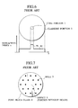
- the conventional optical fiber has a structure as shown in Fig. 6, in which a cladding portion 2 with a low refractive index is arranged around an outer side of a core portion 1 with a high refractive index.
- the photonic crystal optical fibers has a structure as shown in Fig. 7, in which holes 3 are punctured periodically in a single glass such as pure silica glass 4 (see, J.C. Knight, T.A. Birks, P. St. J. Russell and D.M. Atkin, "All-silica single-mode optical fiber with photonic crystal classing", Opt. Lett. 21, 1547-1549 (1996)).
- a defect 5 i.e., a portion without holes
- This defect 5 functions as a core for confining lights.
- a conventional method for manufacturing this optical fiber is shown in Fig. 8A. As shown in Fig. 8A, a hexagonal glass rod 6 with no hole is arranged at a central portion while hexagonal glass pipes 7 with holes are arranged around an outer side of the glass rod 6, and these glass rod 6 and glass pipes 7 are inserted into a glass pipe 8. Then, this is drawn under the high temperature of approximately 2000 °C to form an optical fiber.
- the above described method for manufacturing the optical fiber has the following problems.
- the conventional method has been capable of manufacturing only a short fiber of several hundred meters at most. Moreover, it has been impossible to maintain the hole diameters and hole intervals at high precision in the length direction of the optical fiber, so that it has been impossible to manufacture the optical fiber with a low loss as designed.
- a method for manufacturing an optical fiber having a core portion for waveguiding lights and a plurality of holes arranged around the core portion comprising the steps of: puncturing the holes in a glass rod that is to become the optical fiber, by using an ultrasonic drill; and drawing the glass rod with the holes to form the optical fiber.
- Fig. 3 is a diagram schematically showing the first embodiment of an optical fiber manufacturing method according to the present invention.
- Figs. 4A and 4B are diagrams schematically showing the second embodiment of an optical fiber manufacturing method according to the present invention.
- Fig. 5 is a diagram schematically showing the third embodiment of an optical fiber manufacturing method according to the present invention.
- Fig. 6 is a diagram showing a structure of a conventional optical fiber.
- Fig. 7 is a diagram showing a structure of a photonic crystal fiber.
- Figs. 8A and 8B are diagrams schematically showing the conventional PCF manufacturing method.
- the holes are punctured in a glass rod that is to become an optical fiber by using an ultrasonic drill.
- an ultrasonic drill For example, in the case of puncturing the hole with an inner diameter of 3 mm in the glass by the ultrasonic drill, it is possible to puncture the hole with the inner diameter at a precision of 3 ⁇ 0.01 mm. Also, in the case where the hole interval is 5 mm, it is possible to puncture holes with the hole interval at a precision of 5 ⁇ 0.01 mm.
- the glass rod with holes that is to become a PCF at a high precision.
- the holes punctured by the ultrasonic drill have very few cracks or scars on their inner surfaces. It is also possible to maintain the hole diameters and the hole intervals at high precision along the length direction, so that it is possible to manufacture the glass rod with holes with a precision necessary for the PCF easily.
- the assembling of pipes that has caused problems conventionally is unnecessary, so that the mixing of air bubbles due to the scars also does not occur.
- the drawing processing is applied to this glass rod with holes by a heating furnace.
- the shapes of the holes are hardly changed even after the drawing. Consequently, it is possible to maintain the shapes of the holes as designed after the optical fiber is formed, and it is possible to manufacture the optical fibers with the designed characteristics at high yield.
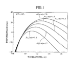
- the dispersion characteristic and the MFD (Mode Field Diameter) characteristic of the PCF are determined by a hole diameter d and a hole interval A. In order to manufacture the PCF at high yield, it is important to have good reproducibility for the hole diameter and the hole interval.
- a glass that is to become an optical fiber must have a low loss (Rayleigh scattering loss, infrared absorption loss, etc.); (2) the shapes of the holes must be maintained along the length direction of the optical fiber; (3) the surface roughness of the holes must be suppressed; and (4) impurities on an inner surface and inside of the hole must be reduced.
- the zero dispersion wavelength is 1.2 ⁇ m in the case where ⁇ is 1.6 ⁇ m, and the zero dispersion wavelength is 1.68 ⁇ m in the case where ⁇ is 1.9 ⁇ m.
- the zero dispersion wavelength is increased by 0.48 ⁇ m.
- the zero dispersion wavelength is changed from 1.2 ⁇ m to 1.4 ⁇ m.
- the hole diameter variation of less than or equal to 0.5% is required in order to suppress the change of the zero dispersion wavelength to about 10 nm.
- Fig. 3 schematically shows the first embodiment of the optical fiber manufacturing method according to the present invention.
- eighteen holes 3 with the inner diameter of 3 mm were punctured at 5 mm interval by the ultrasonic drill 9 in the glass rod 4 with an outer diameter of 40 mm and the length of 200 mm.
- a defect 5 without holes is arranged at a central portion in order to provide the waveguide characteristic. After puncturing the holes, a part of the glass rod is cut out and the shape of the hole was measured. The hole diameter was 3 mm ⁇ 10 ⁇ m, and the hole interval was 5 mm ⁇ 10 ⁇ m.
- the glass rod with holes are heated by an electric furnace and drawn to form the optical fiber with a diameter of 125 ⁇ m.
- the resulting optical fiber had the length of 10 km.
- the optical fiber After the drawing to form the optical fiber, the optical fiber is cut out and the hole diameter and the hole interval were measured by the electron microscope.
- the hole diameter was 9.4 ⁇ m and the hole interval was 15.6 ⁇ m after the drawing.
- this optical fiber had the low light loss of 1 dB/km at the wavelength of 1.3 ⁇ m, and 0.5 dB/km at the wavelength of 1.5 ⁇ m.
- Figs. 4A and 4B schematically show the second embodiment of the optical fiber manufacturing method according to the present invention.
- ninety holes 3 with the hole diameter of 1.4 mm were punctured at the hole interval of 2.9 mm by the ultrasonic drill in the glass rod 4 with an outer diameter of 40 mm and the length of 200 mm, as shown in Fig. 4B.
- a defect 5 without holes is arranged at a central portion.
- the glass rod with holes are drawn until the outer diameter became 8 mm by using the burner. Then, this glass rod is inserted into a glass pipe 10 with the outer diameter of 40 mm and the inner diameter of 9 mm as shown in Fig. 4A, and drawn to form the optical fiber with a diameter of 125 ⁇ m.
- the resulting optical fiber had the length of 5 km.
- the hole diameter was 0.9 ⁇ m and the hole interval was 1.8 ⁇ m after the drawing, and they were constant throughout the entire length of the optical fiber.
- This optical fiber had the low loss of 1 dB/km at the wavelength of 1.3 ⁇ m, and 0.6 dB/km at the wavelength of 1.55 ⁇ m.
- the PCF so manufactured had the zero dispersion wavelength of 1.55 ⁇ m, and the dispersion slope of -0.1 ps/km/nm 2 at the wavelength of 1.55 ⁇ m.
- the dispersion value of ⁇ 0.1 ps/km/nm 2 was obtained at the wavelength of 1.5 to 1.6 ⁇ m.
- Fig. 5 schematically shows the third embodiment of the optical fiber manufacturing method according to the present invention.
- one hundred twenty six holes with the hole diameter of 1.3 mm were punctured at the hole interval of 2.8 mm by the ultrasonic drill in the glass rod 4 with an outer diameter of 40 mm, similarly as in the first embodiment.
- the glass rod with holes are drawn until the outer diameter became 10 mm, and glass fine grains 12 to form a cladding portion are accumulated on an outer surface of the glass rod 4 with holes by using a glass synthetic burner 11 according to the VAD (Vapor phase Axial Deposition) method, as shown in Fig. 5. Then, the glass rod 4 with holes are heated at 1700 °C in the electric furnace to make the glass fine grains transparent and form a starting glass material with the outer diameter of 50 mm and the hole diameter of 0.33 mm.
- VAD Very phase Axial Deposition
- This glass material with holes is heated in the heating furnace and drawn to form the optical fiber with a diameter of 125 ⁇ m.
- the resulting optical fiber had the length of 10 km.
- the hole diameter was 0.83 ⁇ m and the hole interval was 1.8 ⁇ m after the drawing, and they were constant throughout the entire length of the optical fiber.
- This optical fiber had the low loss of 2 dB/km at the wavelength of 1.3 ⁇ m, and 0.5 dB/km at the wavelength of 1.55 ⁇ m.
- the PCF so manufactured had the zero dispersion wavelength of 1.31 ⁇ m, and the dispersion slope of -0.1 ps/km/nm 2 at the wavelength of 1.55 ⁇ m.
- SMF single mode fiber
- the present invention provides a method for manufacturing the photonic crystal optical fibers which is characterized in that the holes are punctured in the glass rod that is to become the optical fiber by using the ultrasonic drill, and then drawn to form the optical fiber, that can be transmission media to be used in the optical communication network and the optical signal processing.
- the optical fibers having a low loss, a constant dispersion characteristic, a hole diameter and a hole interval as designed, and a long length, easily at high yield by puncturing holes in the glass rod at high precision and drawing the glass rod to form the optical fiber.
- the present invention it is possible to puncture several to several hundreds of holes with a small diameter variation (about 1 ⁇ m) at the equal hole interval.
- the shapes of the holes remain similar to the initial shapes of the holes so that the optical fiber as designed can be manufactured easily.
- there is no glass connecting portion between adjacent holes so that the loss due to the structural mismatching will not occur.
- the optical fibers with a long length and a low loss as designed can be manufactured at high yield.
- the optical fibers so manufactured can be utilized widely as devices for compensating dispersion and utilizing the nonlinear effect, optical fibers for maintaining polarization, etc.
Landscapes
- Chemical & Material Sciences (AREA)
- Engineering & Computer Science (AREA)
- Materials Engineering (AREA)
- Organic Chemistry (AREA)
- Life Sciences & Earth Sciences (AREA)
- General Life Sciences & Earth Sciences (AREA)
- Geochemistry & Mineralogy (AREA)
- Manufacturing & Machinery (AREA)
- Chemical Kinetics & Catalysis (AREA)
- General Chemical & Material Sciences (AREA)
- Physics & Mathematics (AREA)
- Crystallography & Structural Chemistry (AREA)
- Optics & Photonics (AREA)
- Optical Fibers, Optical Fiber Cores, And Optical Fiber Bundles (AREA)
- Perforating, Stamping-Out Or Severing By Means Other Than Cutting (AREA)
- Manufacture, Treatment Of Glass Fibers (AREA)
Applications Claiming Priority (2)
| Application Number | Priority Date | Filing Date | Title |
|---|---|---|---|
| JP2002001980 | 2002-01-09 | ||
| JP2002001980A JP2003206149A (ja) | 2002-01-09 | 2002-01-09 | 光ファイバの製造方法 |
Publications (2)
| Publication Number | Publication Date |
|---|---|
| EP1327611A2 true EP1327611A2 (fr) | 2003-07-16 |
| EP1327611A3 EP1327611A3 (fr) | 2004-01-28 |
Family
ID=19190693
Family Applications (1)
| Application Number | Title | Priority Date | Filing Date |
|---|---|---|---|
| EP03000005A Withdrawn EP1327611A3 (fr) | 2002-01-09 | 2003-01-02 | Procédé de fabrication d'une fibre optique creuse utilisant une perceuse à ultrasons |
Country Status (3)
| Country | Link |
|---|---|
| US (1) | US20030136154A1 (fr) |
| EP (1) | EP1327611A3 (fr) |
| JP (1) | JP2003206149A (fr) |
Cited By (1)
| Publication number | Priority date | Publication date | Assignee | Title |
|---|---|---|---|---|
| WO2009010317A1 (fr) * | 2007-07-15 | 2009-01-22 | Heraeus Quarzglas Gmbh & Co. Kg | Procédé de fabrication d'un composant optique ayant des trous longitudinaux |
Families Citing this family (6)
| Publication number | Priority date | Publication date | Assignee | Title |
|---|---|---|---|---|
| US20070062337A1 (en) * | 2003-06-30 | 2007-03-22 | Guojun Dai | Method and apparatus for drilling preforms for holey optical fibers |
| JP4252005B2 (ja) * | 2004-03-19 | 2009-04-08 | 信越化学工業株式会社 | 空孔ファイバ用ガラス母材の製造方法、空孔ファイバ及びその製造方法 |
| US8755658B2 (en) * | 2007-02-15 | 2014-06-17 | Institut National D'optique | Archimedean-lattice microstructured optical fiber |
| US8133593B2 (en) * | 2008-06-26 | 2012-03-13 | Corning Incorporated | Pre-form for and methods of forming a hollow-core slotted PBG optical fiber for an environmental sensor |
| JP5644692B2 (ja) * | 2011-06-21 | 2014-12-24 | 住友電気工業株式会社 | 光ファイバ母材製造方法 |
| CN107132613A (zh) * | 2017-06-08 | 2017-09-05 | 中国电子科技集团公司电子科学研究院 | 一种泄漏通道型光纤及其生产方法 |
Family Cites Families (15)
| Publication number | Priority date | Publication date | Assignee | Title |
|---|---|---|---|---|
| US2818686A (en) * | 1956-02-28 | 1958-01-07 | Gulton Ind Inc | Rotating ultrasonic drill |
| US4767430A (en) * | 1985-08-15 | 1988-08-30 | Corning Glass Works | Optical fiber-device interconnection and method |
| US4820322A (en) * | 1986-04-28 | 1989-04-11 | American Telephone And Telegraph Company At&T Bell Laboratories | Method of and apparatus for overcladding a glass rod |
| ES2018519B3 (es) * | 1986-08-29 | 1991-04-16 | American Telephone & Telegraph Company | Metodo de recubrimiento de hollin de una preforma optica. |
| EP0630864A3 (fr) * | 1993-05-24 | 1995-05-24 | Sumitomo Electric Industries | Procédé de fabrication d'une fibre optique à conservation de polarisation. |
| CA2202586C (fr) * | 1996-04-15 | 2003-05-06 | Masashi Onishi | Fibre compensatrice de dispersion et systeme de transmission optique comprenant cette fibre |
| US6131415A (en) * | 1997-06-20 | 2000-10-17 | Lucent Technologies Inc. | Method of making a fiber having low loss at 1385 nm by cladding a VAD preform with a D/d<7.5 |
| US6411762B1 (en) * | 1997-12-09 | 2002-06-25 | Scientific-Atlanta, Inc. | Optical fiber with irregularities at cladding boundary |
| US6418258B1 (en) * | 2000-06-09 | 2002-07-09 | Gazillion Bits, Inc. | Microstructured optical fiber with improved transmission efficiency and durability |
| US7155097B2 (en) * | 2001-03-09 | 2006-12-26 | Crystal Fibre A/S | Fabrication of microstructured fibres |
| WO2003009028A1 (fr) * | 2001-07-20 | 2003-01-30 | The University Of Sydney | Realisation de preformes pour la fabrication de fibres |
| US6603600B2 (en) * | 2001-11-21 | 2003-08-05 | Coherent, Inc. | Chirped pulse amplification method and apparatus |
| US6775450B2 (en) * | 2001-12-07 | 2004-08-10 | Nortel Networks Limited | Micro-structured optical fibers |
| US6707957B1 (en) * | 2001-12-18 | 2004-03-16 | Nortel Networks Limited | Compensating for polarisation mode dispersion in optical transmission fibers |
| US6775448B2 (en) * | 2002-11-05 | 2004-08-10 | Mesophotonics Limited | Optical device |
-
2002
- 2002-01-09 JP JP2002001980A patent/JP2003206149A/ja active Pending
-
2003
- 2003-01-02 EP EP03000005A patent/EP1327611A3/fr not_active Withdrawn
- 2003-01-09 US US10/339,228 patent/US20030136154A1/en not_active Abandoned
Cited By (2)
| Publication number | Priority date | Publication date | Assignee | Title |
|---|---|---|---|---|
| WO2009010317A1 (fr) * | 2007-07-15 | 2009-01-22 | Heraeus Quarzglas Gmbh & Co. Kg | Procédé de fabrication d'un composant optique ayant des trous longitudinaux |
| DE102007033086A1 (de) | 2007-07-15 | 2009-01-29 | Heraeus Quarzglas Gmbh & Co. Kg | Verfahren zur Herstellung eines optischen Bauteils mit Längsbohrungen, sowie mikrostrukturierte optische Faser |
Also Published As
| Publication number | Publication date |
|---|---|
| EP1327611A3 (fr) | 2004-01-28 |
| US20030136154A1 (en) | 2003-07-24 |
| JP2003206149A (ja) | 2003-07-22 |
Similar Documents
| Publication | Publication Date | Title |
|---|---|---|
| US7266275B2 (en) | Nonlinear optical fibre method of its production and use thereof | |
| JP4465527B2 (ja) | 微細構造光ファイバ、プリフォーム及び微細構造光ファイバの製造方法 | |
| JP3786010B2 (ja) | 光ファイバ | |
| AU2004200003A1 (en) | Microstructured optical fiber | |
| JP2010501894A (ja) | アルカリ金属酸化物を含有する光ファイバ | |
| US20110094269A1 (en) | Optical fiber manufacturing method | |
| US9904007B2 (en) | Photonic band gap fibers using a jacket with a depressed softening temperature | |
| JPWO2001079902A1 (ja) | 光ファイバ | |
| CA2565879C (fr) | Grande longueur d'onde, fibre de mode simple a noyau de silice pure et procede de fabrication de celle-ci | |
| EP2056135B1 (fr) | Fibre optique et guide de lumière | |
| KR100963812B1 (ko) | 미세구조 광섬유 및 이의 제조방법 | |
| EP2071369A1 (fr) | Fibre trouée | |
| JP2007536580A5 (fr) | ||
| US20060213230A1 (en) | Method of manufacturing microstructured optical fiber | |
| EP1327611A2 (fr) | Procédé de fabrication d'une fibre optique creuse utilisant une perceuse à ultrasons | |
| CN111796361A (zh) | 一种宽带平坦透过的多芯光纤耦合器的制备方法及其应用 | |
| WO2015125555A1 (fr) | Fibre optique et procédé de fabrication de fibre optique | |
| WO2001084198A1 (fr) | Fibre optique et son procede de realisation | |
| JP3917115B2 (ja) | 光ファイバの製造方法 | |
| EP1576400B1 (fr) | Procede de production d'une fibre optique a faible perte d'epissure | |
| JP2004347817A (ja) | 分散フラットファイバ | |
| EP1584958A1 (fr) | Fibre optique à cristal photonique permettant une transmission monomode et préforme pour cette fibre | |
| WO2010107138A1 (fr) | Fibre en cristal photonique à dispersion chromatique | |
| JP3866696B2 (ja) | 光ファイバの製造方法 | |
| JP2003040637A (ja) | 光ファイバの製造方法および光ファイバ |
Legal Events
| Date | Code | Title | Description |
|---|---|---|---|
| PUAI | Public reference made under article 153(3) epc to a published international application that has entered the european phase |
Free format text: ORIGINAL CODE: 0009012 |
|
| 17P | Request for examination filed |
Effective date: 20030102 |
|
| AK | Designated contracting states |
Designated state(s): AT BE BG CH CY CZ DE DK EE ES FI FR GB GR HU IE IT LI LU MC NL PT SE SI SK TR |
|
| AX | Request for extension of the european patent |
Extension state: AL LT LV MK RO |
|
| PUAL | Search report despatched |
Free format text: ORIGINAL CODE: 0009013 |
|
| AK | Designated contracting states |
Kind code of ref document: A3 Designated state(s): AT BE BG CH CY CZ DE DK EE ES FI FR GB GR HU IE IT LI LU MC NL PT SE SI SK TR |
|
| AX | Request for extension of the european patent |
Extension state: AL LT LV MK RO |
|
| AKX | Designation fees paid |
Designated state(s): DE FR GB |
|
| 17Q | First examination report despatched |
Effective date: 20041220 |
|
| RIC1 | Information provided on ipc code assigned before grant |
Ipc: G02B 6/00 20060101ALI20100727BHEP Ipc: C03B 37/014 20060101ALI20100727BHEP Ipc: C03B 37/012 20060101AFI20100727BHEP |
|
| STAA | Information on the status of an ep patent application or granted ep patent |
Free format text: STATUS: THE APPLICATION IS DEEMED TO BE WITHDRAWN |
|
| 18D | Application deemed to be withdrawn |
Effective date: 20100802 |