EP1328323B1 - Trägerplatte zwischen ski und bindung - Google Patents
Trägerplatte zwischen ski und bindung Download PDFInfo
- Publication number
- EP1328323B1 EP1328323B1 EP01976435A EP01976435A EP1328323B1 EP 1328323 B1 EP1328323 B1 EP 1328323B1 EP 01976435 A EP01976435 A EP 01976435A EP 01976435 A EP01976435 A EP 01976435A EP 1328323 B1 EP1328323 B1 EP 1328323B1
- Authority
- EP
- European Patent Office
- Prior art keywords
- plate
- baseplate
- boot
- ski
- retaining
- Prior art date
- Legal status (The legal status is an assumption and is not a legal conclusion. Google has not performed a legal analysis and makes no representation as to the accuracy of the status listed.)
- Expired - Lifetime
Links
- BASFCYQUMIYNBI-UHFFFAOYSA-N platinum Chemical compound [Pt] BASFCYQUMIYNBI-UHFFFAOYSA-N 0.000 description 8
- 238000010276 construction Methods 0.000 description 3
- 230000010355 oscillation Effects 0.000 description 3
- 239000003190 viscoelastic substance Substances 0.000 description 3
- 239000000463 material Substances 0.000 description 2
- 238000004026 adhesive bonding Methods 0.000 description 1
- 230000000295 complement effect Effects 0.000 description 1
- 238000013016 damping Methods 0.000 description 1
- 238000005553 drilling Methods 0.000 description 1
- 239000000835 fiber Substances 0.000 description 1
- 230000014759 maintenance of location Effects 0.000 description 1
- 238000003466 welding Methods 0.000 description 1
Images



Classifications
-
- A—HUMAN NECESSITIES
- A63—SPORTS; GAMES; AMUSEMENTS
- A63C—SKATES; SKIS; ROLLER SKATES; DESIGN OR LAYOUT OF COURTS, RINKS OR THE LIKE
- A63C9/00—Ski bindings
- A63C9/003—Non-swivel sole plate fixed on the ski
Definitions
- the invention relates to an interface device between a ski and retaining elements of a boot on a ski.
- the invention relates to a device of the type described in the patent application published under the number FR 2 777 472.
- This device comprises two plates articulated to the ski around a transverse axis, each of the plates receiving a retaining element of the shoe.
- An object of the present invention is to propose other modes of connection of the plates to the ski.
- an elastically deformable connection zone between the plate and the base defines a notional hinge axis.
- the plate and the base are assembled by interlocking complementary shapes.
- Figure 1 shows the middle part of a ski 1 which is surmounted by two front and rear retaining elements 2 and 3 of a shoe.
- the retainers are of any suitable type and will not be described in detail. In a known manner, they are intended to retain means of jaws 2a and 3a the front and rear ends of a shoe whose sole rests on support plates, respectively 2b and 3b.
- the retaining elements are mounted on plates 6, 7, which form the interface device.
- each of the plates 6, 7 comprises an upper plate 8, 9 and a lower base 10, 11 connected by an elastically deformable zone 12, 13.
- the plate 6 is shown in perspective in Figure 2. Its plate 8 has an upper surface 8a provided to receive the front retainer. For this, the plate has in plan a shape and dimensions that correspond to those of the retaining element. Optionally, a plate longer than the length of the element can be provided, and series of holes for the assembly screws of the element which allow the assembly in different longitudinal positions.
- the base 10 is located under the tray which is kept raised relative to it.
- the base is assembled to the ski by any appropriate means, including screws that are accessible through drilling the plate.
- FIG. 2 shows a bore 14 of the base which is provided to receive an assembly screw, and bores 15, 16, 17 of the plate which make it possible to access the screws of the other bores of the 'base.
- the plate 6 could be glued or welded to the upper surface of the ski or integrated into the structure of the ski.
- the plate and the base are connected by an area 12 of reduced section which is elastically deformable.
- the zone 12 extends transversely over the entire width of the plate.
- the assembly formed by the plate, the base and the elastically deformable zone is monobloc, it is made for example of a plastic material optionally loaded with fibers.
- the elastically deformable zone 12 is located towards the support plate 2b of the retaining element.
- the base extends on either side of the deformable zone 12.
- cushions of damping material in particular of the viscoelastic type, are interposed between the plate and the base on either side of the zone. 12.
- the cushion 20 located towards the middle of the ski is harder than the other cushion 19 located outwardly.
- the rear plate is similarly constructed, with its plate 9, its base 11 connected by an elastically deformable zone 13 located approximately below the support plate 3b.
- Two cushions 21 and 22 are provided between the plate and the base, preferably with the inner cushion 22 harder than the outer cushion 21.
- the two elastically deformable zones 12 and 13 form fictitious joints around which the plates can oscillate relative to the bases.
- the plates 8 and 9 or the retaining elements are connected to each other by a connecting bar which opposes a relative distance of the trays, but not to a relative approximation.
- a link of this type is described in patent application FR 2 777 472 cited in the preamble.
- Figure 3 relates to an alternative embodiment of the invention. It represents a plate 25 which will be assumed to be a front plate, the rear plate being constructed according to the same mode of construction.
- the plate 25 has an upper plate 26 with a mounting zone 27 provided for the retaining element. In its middle part, the plate has a bowl 28 of cylindrical shape of revolution about a fictitious transverse axis located above the plate.
- the plate 26 rests by its bowl on a base comprising a support 30 and a counter-support 31.
- the bowl is sandwiched between the support and the counter-support, and the contact surfaces of these two elements marry the cylindrical faces of revolution of the bowl.
- the bowl protrudes forward and backward of the support and the counter-support.
- the assembly formed by the support, the plate and the counter-support is assembled to the ski by through screws 32 to 35 which are screwed into the ski.
- the plate has lights 36 to 39 oriented longitudinally for the passage of the screws. The screws are tightened to allow the plate to slide between the support 30 and the counter-support 31 on a limited amplitude, which amounts to an oscillation movement around the fictitious axis of revolution of the bowl.
- the front and rear portions of the tray rest on cushions 41 and 42 of viscoelastic material. These cushions dampen the oscillation movement of the tray.
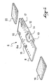
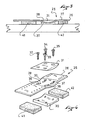
- FIGS. 5 and 6 relate to another alternative embodiment.
- the plate 45 comprises a plate 46 mounted on a base 47.
- the base has in its central portion a rib 48 projecting whose upper portion 49 has a section in rounded shape of revolution about a transverse axis. This rounded shape covers an angle greater than 180 degrees.
- the plate has in its lower part a groove whose shape matches that of the rib 48 to ensure the retention of the plate 46 and allow oscillation of the plate relative to the base around the axis of revolution of the rounded shape.
- the plate is mounted on the base by the side, and it is held on the rib of the base by any suitable means, for example by washers 50 screwed into the rib.
- resiliently deformable cushions 51, 52 are interposed between the plate and the base.
- the plate 54 is formed by a plate 55 and a base 56.
- Each of these two elements is made from a profile having an inverted “U” section, with a bottom, respectively 55a, 56a, and two wings, respectively 55b, 55c, 56b, 56c.
- the tray 55 has an upper surface for receiving a retainer.
- the two profiles are embedded one inside the other, the external width of the base being equal to operating clearance close to the inside width of the tray.
- the height of the wings of the plate is greater than that of the wings of the base so that the bottom 55a of the plate is raised relative to the bottom 56a of the base.
- the wings 55v, 56b and 55c, 56c are assembled by rivets 58, 59 which are placed in orifices pierced along the same transverse axis.
- the rivets could be replaced by equivalent means, including an axc crimped at its ends, a bolt or other.
- a filter cushion 60 is interposed between the bottoms of the base and the plate. Possibly the cushion is in two parts which can be of different hardness.
- a preferred ski for this type of plate is shown in Figure 9. It has in its upper part of the lateral recesses 62, 63, 64, 65 which are provided in pairs to accommodate the wings of the front and rear plates.
- Each of the plates, in particular the plate 54 is assembled to the ski by screws which assemble the bottom of the base to the upper surface of the ski. These screws are accessible through openings 71 and 72 of the tray. Instead of being screwed, the bottom of the base could be glued or welded to the ski.
- the assembly is provided so that the plate oscillates relative to the base around the imaginary axis materialized by the alignment of the two rivets 58, 59.
- the plate 70 comprises a plate 71 and a base 72. These elements are formed from a section having a section "U”, with the wings directed upwards, unlike the case previous.
- the assembly mode of the plate 71 and the base 72 is made by means of rivets 73, 74 as in the previous case, and preferably with a filter cushion 75 between the plate and the base.
- the retainer is intended to be assembled to the tray between the wings.
- the spacing of the wings is planned accordingly.
- the retaining element has recesses in which are housed the wings.
- the plate is assembled by screwing, gluing, or welding the base on the ski which is here a standard ski.
- the plate and the base are likely to oscillate relative to each other about the fictitious axis formed by the alignment of the two rivets 73 and 74.
- the plate and the base could be for the first a U-shaped profile upside down and for the other a U-shaped profile at the place with an assembly by rivets at the wings.
- the plates 78 and 79 have generally the same mode of construction as that described in FIGS. 1 and 2, with an upper plate 80, 81, a base 82, 83 connected by a deformable zone 84, 85 .
- Each of the bases 82, 83 is housed in a recess 86, 87 of the ski of which it matches the shape.
- the recesses 86 and 87 extend transversely and they are rounded in a longitudinal direction.
- the bases are glued or welded in the recesses. Preferably, they are flush with the upper surface of the ski on each side of the recess.
- cushions of viscoelastic material are interposed between the plates and the upper surface of the bases or the ski.
- the trays or the retaining elements could be connected by a connecting bar.
- the invention is not limited to the field of skiing, it could find other applications in the field of gliding boards.
Landscapes
- Footwear And Its Accessory, Manufacturing Method And Apparatuses (AREA)
- Golf Clubs (AREA)
- Non-Reversible Transmitting Devices (AREA)
- Devices For Checking Fares Or Tickets At Control Points (AREA)
- Fittings On The Vehicle Exterior For Carrying Loads, And Devices For Holding Or Mounting Articles (AREA)
Claims (9)
- Zwischenvorrichtung zwischen einem Gleitbrett und Elementen zum Halten eines Schuhs auf dem Brett, aufweisend mindestens eine Platte (6, 7), welche eine obere Plattform (8, 80, 81) mit einer Montagezone an ihrer oberen Oberfläche aufweist, welche für ein Element zum Halten des Schuhs vorgesehen ist, und an ihrem unteren Teil eine Basis (10, 82, 83), welche vorgesehen ist, um an dem Ski montiert zu werden, dadurch gekennzeichnet, dass die Plattform (8, 80, 81) mit der Basis (10, 82, 83) eine einstückige Gesamtheit bildet und dass sie mit ihrer Basis (10) über eine elastisch verformbare Zone (12, 84, 85) von reduziertem Querschnitt verbunden ist, welche es der Plattform ermöglicht, sich relativ zu der Basis hin- und herzubewegen.
- Vorrichtung nach Anspruch 1, dadurch gekennzeichnet, dass sich die elastisch verformbare Zone (12, 84, 85) transversal über die gesamte Breite der Platte erstreckt.
- Zwischenvorrichtung zwischen einem Gleitbrett und Elementen zum Halten eines Schuhs auf dem Brett, aufweisend mindestens eine Platte (25), welche eine obere Plattform (26) mit einer Montagezone an ihrer oberen Oberfläche aufweist, welche für ein Element zum Halten des Schuhs vorgesehen ist, und an ihrem unteren Teil eine Basis (30, 31), welche vorgesehen ist, um an dem Ski montiert zu werden, dadurch gekennzeichnet, dass die Plattform (26) in ihrem mittleren Teil eine erweiterte Mulde (28) von einer um eine Achse rotationszylindrischen Form aufweist, welche quer ausgerichtet ist, und dass die Plattform auf der Mulde über einem Träger (30) ruht, der zur Basis gehört und dessen Kontaktoberfläche sich der zylindrischen Form der Plattform anschmiegt, wobei der Plattform eine Oszillationsbewegung um die fiktive Drehachse der Mulde ermöglicht wird.
- Vorrichtung nach Anspruch 3, dadurch gekennzeichnet, dass die Plattform auf Höhe ihrer Mulde (28) sandwichförmig zwischen dem Träger (30) und einem Gegenträger (31) umgriffen ist.
- Zwischenvorrichtung zwischen einem Gleitbrett und Elementen zum Halten eines Schuhs auf dem Brett, aufweisend mindestens eine Platte (45), welche eine obere Plattform (46) mit einer Montagezone an ihrer oberen Oberfläche aufweist, welche für ein Element zum Halten des Schuhs vorgesehen ist, und an ihrem unteren Teil eine Basis (47), welche vorgesehen ist, um an dem Ski montiert zu werden, dadurch gekennzeichnet, dass die Plattform mit der Basis verbunden ist, weil die Basis (47) eine Rippe (48) aufweist, deren oberer Teil eine abgerundete Form aufweist, welche einen größeren Winkel als 180 Grad abdeckt, und dass die Plattform eine Nut (49) aufweist, welche sich der abgerundeten Form der Rippe anschmiegt.
- Zwischenvorrichtung zwischen einem Gleitbrett und Elementen zum Halten eines Schuhs auf dem Brett, aufweisend mindestens eine Platte (54, 70), welche eine obere Plattform (55, 71) mit einer Montagezone an ihrer oberen Oberfläche aufweist, welche für ein Element zum Halten des Schuhs vorgesehen ist, und an ihrem unteren Teil eine Basis (56, 72), welche vorgesehen ist, um an dem Ski montiert zu werden, dadurch gekennzeichnet, dass die Plattform (55, 71) und die Basis (56, 72) "U"-förmige Profile sind, welche ineinander eingesetzt sind, mit einem Boden und Flügeln, wobei die Plattform (55, 71) und die Basis (56, 72) über Nieten (58, 59, 73, 74) montiert sind, welche die Flügel durchqueren.
- Vorrichtung nach den Ansprüchen 1, 3, 5 und 6, dadurch gekennzeichnet, dass elastisch verformbare Polster (19, 20, 41, 42, 51, 52, 60, 75) zwischen die Plattform und die Basis auf jeder Seite der Verbindung gesetzt sind.
- Vorrichtung nach Anspruch 7, dadurch gekennzeichnet, dass das Polster, welches in Richtung zur Mitte (20, 42, 52) hin angeordnet ist, härter ist als das Polster (19,41,51), welches auf der äußeren Seite angeordnet ist.
- Gesamtheit zum Halten eines Schuhs auf einem Gleitbrett, dadurch gekennzeichnet, dass sie eine Zwischenvorrichtung nach irgendeinem der vorangegangenen Ansprüche aufweist.
Applications Claiming Priority (3)
| Application Number | Priority Date | Filing Date | Title |
|---|---|---|---|
| FR0013961A FR2815547B1 (fr) | 2000-10-24 | 2000-10-24 | Dispositif interface entre un ski et des elements de retenue d'une chaussure sur un ski |
| FR0013961 | 2000-10-24 | ||
| PCT/FR2001/003184 WO2002034342A1 (fr) | 2000-10-24 | 2001-10-15 | Dispositif interface entre un ski et des elements de retenue d"une chaussure sur un ski |
Publications (2)
| Publication Number | Publication Date |
|---|---|
| EP1328323A1 EP1328323A1 (de) | 2003-07-23 |
| EP1328323B1 true EP1328323B1 (de) | 2007-03-21 |
Family
ID=8855923
Family Applications (1)
| Application Number | Title | Priority Date | Filing Date |
|---|---|---|---|
| EP01976435A Expired - Lifetime EP1328323B1 (de) | 2000-10-24 | 2001-10-15 | Trägerplatte zwischen ski und bindung |
Country Status (5)
| Country | Link |
|---|---|
| EP (1) | EP1328323B1 (de) |
| AT (1) | ATE357281T1 (de) |
| DE (1) | DE60127432T2 (de) |
| FR (1) | FR2815547B1 (de) |
| WO (1) | WO2002034342A1 (de) |
Families Citing this family (1)
| Publication number | Priority date | Publication date | Assignee | Title |
|---|---|---|---|---|
| AT515397B1 (de) * | 2014-02-13 | 2015-11-15 | Tyrolia Technology Gmbh | Vorderbacken einer Sicherheitsskibindung |
Family Cites Families (4)
| Publication number | Priority date | Publication date | Assignee | Title |
|---|---|---|---|---|
| WO1995007737A1 (en) * | 1993-09-13 | 1995-03-23 | Marco Maggiolo | Device for improving the efficiency and controllability of skis |
| AT405140B (de) * | 1996-10-09 | 1999-05-25 | Schi Lenz Gesmbh | Plattenförmiger bindungsträger |
| FR2777472B1 (fr) | 1998-04-17 | 2000-07-13 | Salomon Sa | Dispositif interface entre un ski et des elements de retenue d'une chaussure sur le ski |
| EP0985433A1 (de) * | 1998-09-14 | 2000-03-15 | Hans-Peter Bigler | Skibindungsträger |
-
2000
- 2000-10-24 FR FR0013961A patent/FR2815547B1/fr not_active Expired - Fee Related
-
2001
- 2001-10-15 EP EP01976435A patent/EP1328323B1/de not_active Expired - Lifetime
- 2001-10-15 WO PCT/FR2001/003184 patent/WO2002034342A1/fr not_active Ceased
- 2001-10-15 AT AT01976435T patent/ATE357281T1/de not_active IP Right Cessation
- 2001-10-15 DE DE60127432T patent/DE60127432T2/de not_active Expired - Fee Related
Also Published As
| Publication number | Publication date |
|---|---|
| ATE357281T1 (de) | 2007-04-15 |
| FR2815547A1 (fr) | 2002-04-26 |
| EP1328323A1 (de) | 2003-07-23 |
| DE60127432T2 (de) | 2007-11-29 |
| FR2815547B1 (fr) | 2003-02-07 |
| WO2002034342A1 (fr) | 2002-05-02 |
| DE60127432D1 (de) | 2007-05-03 |
Similar Documents
| Publication | Publication Date | Title |
|---|---|---|
| EP1844673B1 (de) | Dämpfungssystem für einen Schuh | |
| EP0543743B1 (de) | Ski mit nicht rechteckigem Schnitt | |
| EP1166668A2 (de) | Sportschuh mit einer an einer flexiblen Fersenkappe befestigten steifen Fersenkappe | |
| EP0938917A1 (de) | Vorrichtung zwischen einem Ski und einen Bindung | |
| EP0465794A1 (de) | Ski mit gerippter Oberfläche | |
| FR2673880A1 (fr) | Guide-chaine en trois parties pour scies a moteur a chaine. | |
| EP1125604B1 (de) | Snowboardbindung | |
| FR2834906A1 (fr) | Perfectionnement pour planche de glisse sur neige | |
| EP1108452B1 (de) | Verbindungselement zum Kuppeln eines Stiefels mit einem Snowboard | |
| EP0950427A1 (de) | Trägerplatte zwischen Ski und Bindung | |
| EP1523375B1 (de) | In-line rollschuh rahmen | |
| WO1991009654A1 (fr) | Dispositif d'appui, sur un ski, de la partie anterieure de la semelle d'une chaussure | |
| WO2002034342A1 (fr) | Dispositif interface entre un ski et des elements de retenue d"une chaussure sur un ski | |
| EP1424108B1 (de) | Schneegleitbrett mit seitliche Abstützungplatte | |
| EP1621237B1 (de) | Vorrichtung zum binden eines Schuhs auf einem Gleitbrett | |
| FR2774001A1 (fr) | Dispositif interface entre un ski et les elements de retenue d'une chaussure | |
| EP1106217A1 (de) | Trägerplatte für ein Snowboard | |
| FR2655867A1 (fr) | Fixation de securite de ski alpin. | |
| FR2800623A1 (fr) | Dispositif interface entre un ski et des elements de retenue d'une chaussure sur le ski et ski ainsi equipe | |
| FR2796852A1 (fr) | Dispositif interface entre une chaussure et un ski | |
| FR2810893A1 (fr) | Dispositif interface entre un ski alpin et des elements de retenue de la chaussure sur le ski | |
| FR2774000A1 (fr) | Dispositif interface entre un ski et les elements de retenue d'une chaussure | |
| FR2810891A1 (fr) | Dispositif interface entre un ski et des elements de retenue d'une chaussure sur le ski | |
| FR2883485A1 (fr) | Chassis pour patin | |
| FR2815546A1 (fr) | Dispositif interface entre un ski et des elements de retenue d'une chaussure sur le ski |
Legal Events
| Date | Code | Title | Description |
|---|---|---|---|
| PUAI | Public reference made under article 153(3) epc to a published international application that has entered the european phase |
Free format text: ORIGINAL CODE: 0009012 |
|
| 17P | Request for examination filed |
Effective date: 20030422 |
|
| AK | Designated contracting states |
Designated state(s): AT BE CH CY DE DK ES FI FR GB GR IE IT LI LU MC NL PT SE TR |
|
| RBV | Designated contracting states (corrected) |
Designated state(s): AT CH DE IT LI |
|
| GRAP | Despatch of communication of intention to grant a patent |
Free format text: ORIGINAL CODE: EPIDOSNIGR1 |
|
| GRAS | Grant fee paid |
Free format text: ORIGINAL CODE: EPIDOSNIGR3 |
|
| GRAA | (expected) grant |
Free format text: ORIGINAL CODE: 0009210 |
|
| AK | Designated contracting states |
Kind code of ref document: B1 Designated state(s): AT CH DE IT LI |
|
| REG | Reference to a national code |
Ref country code: CH Ref legal event code: EP |
|
| REF | Corresponds to: |
Ref document number: 60127432 Country of ref document: DE Date of ref document: 20070503 Kind code of ref document: P |
|
| PLBE | No opposition filed within time limit |
Free format text: ORIGINAL CODE: 0009261 |
|
| STAA | Information on the status of an ep patent application or granted ep patent |
Free format text: STATUS: NO OPPOSITION FILED WITHIN TIME LIMIT |
|
| PGFP | Annual fee paid to national office [announced via postgrant information from national office to epo] |
Ref country code: DE Payment date: 20071011 Year of fee payment: 7 |
|
| 26N | No opposition filed |
Effective date: 20071227 |
|
| PGFP | Annual fee paid to national office [announced via postgrant information from national office to epo] |
Ref country code: AT Payment date: 20071011 Year of fee payment: 7 Ref country code: CH Payment date: 20071015 Year of fee payment: 7 Ref country code: IT Payment date: 20071026 Year of fee payment: 7 |
|
| REG | Reference to a national code |
Ref country code: CH Ref legal event code: PL |
|
| PG25 | Lapsed in a contracting state [announced via postgrant information from national office to epo] |
Ref country code: IT Free format text: LAPSE BECAUSE OF NON-PAYMENT OF DUE FEES Effective date: 20081015 Ref country code: DE Free format text: LAPSE BECAUSE OF NON-PAYMENT OF DUE FEES Effective date: 20090501 Ref country code: AT Free format text: LAPSE BECAUSE OF NON-PAYMENT OF DUE FEES Effective date: 20081015 |
|
| PG25 | Lapsed in a contracting state [announced via postgrant information from national office to epo] |
Ref country code: LI Free format text: LAPSE BECAUSE OF NON-PAYMENT OF DUE FEES Effective date: 20081031 Ref country code: CH Free format text: LAPSE BECAUSE OF NON-PAYMENT OF DUE FEES Effective date: 20081031 |