EP1328695B1 - Dispositif pour l'initialisation d'un processus d'ouverture et de verrouillage d'un vehicule automobile - Google Patents
Dispositif pour l'initialisation d'un processus d'ouverture et de verrouillage d'un vehicule automobile Download PDFInfo
- Publication number
- EP1328695B1 EP1328695B1 EP01987836A EP01987836A EP1328695B1 EP 1328695 B1 EP1328695 B1 EP 1328695B1 EP 01987836 A EP01987836 A EP 01987836A EP 01987836 A EP01987836 A EP 01987836A EP 1328695 B1 EP1328695 B1 EP 1328695B1
- Authority
- EP
- European Patent Office
- Prior art keywords
- electrode
- proximity sensor
- motor vehicle
- electrodes
- signal
- Prior art date
- Legal status (The legal status is an assumption and is not a legal conclusion. Google has not performed a legal analysis and makes no representation as to the accuracy of the status listed.)
- Expired - Lifetime
Links
- 230000000977 initiatory effect Effects 0.000 title claims abstract description 9
- 238000000034 method Methods 0.000 title claims abstract description 9
- 230000008569 process Effects 0.000 title claims abstract description 8
- 238000013459 approach Methods 0.000 claims abstract description 16
- 238000011156 evaluation Methods 0.000 claims description 33
- 238000013475 authorization Methods 0.000 claims description 6
- 230000001960 triggered effect Effects 0.000 claims description 3
- 238000012216 screening Methods 0.000 claims 1
- 230000008859 change Effects 0.000 description 10
- 230000004044 response Effects 0.000 description 7
- 238000013461 design Methods 0.000 description 5
- 230000004913 activation Effects 0.000 description 3
- 238000000576 coating method Methods 0.000 description 3
- 238000001514 detection method Methods 0.000 description 3
- 238000011161 development Methods 0.000 description 3
- 230000018109 developmental process Effects 0.000 description 3
- 238000000926 separation method Methods 0.000 description 3
- VYZAMTAEIAYCRO-UHFFFAOYSA-N Chromium Chemical compound [Cr] VYZAMTAEIAYCRO-UHFFFAOYSA-N 0.000 description 2
- 230000009471 action Effects 0.000 description 2
- 239000011248 coating agent Substances 0.000 description 2
- 230000003213 activating effect Effects 0.000 description 1
- 230000003750 conditioning effect Effects 0.000 description 1
- 239000004020 conductor Substances 0.000 description 1
- 230000009849 deactivation Effects 0.000 description 1
- 230000001419 dependent effect Effects 0.000 description 1
- 238000010586 diagram Methods 0.000 description 1
- 230000005684 electric field Effects 0.000 description 1
- 230000008030 elimination Effects 0.000 description 1
- 238000003379 elimination reaction Methods 0.000 description 1
- 210000003811 finger Anatomy 0.000 description 1
- 239000012528 membrane Substances 0.000 description 1
- 238000012545 processing Methods 0.000 description 1
- 230000035945 sensitivity Effects 0.000 description 1
- 238000007493 shaping process Methods 0.000 description 1
- 210000003813 thumb Anatomy 0.000 description 1
Images



Classifications
-
- E—FIXED CONSTRUCTIONS
- E05—LOCKS; KEYS; WINDOW OR DOOR FITTINGS; SAFES
- E05B—LOCKS; ACCESSORIES THEREFOR; HANDCUFFS
- E05B81/00—Power-actuated vehicle locks
- E05B81/54—Electrical circuits
- E05B81/64—Monitoring or sensing, e.g. by using switches or sensors
- E05B81/76—Detection of handle operation; Detection of a user approaching a handle; Electrical switching actions performed by door handles
-
- E—FIXED CONSTRUCTIONS
- E05—LOCKS; KEYS; WINDOW OR DOOR FITTINGS; SAFES
- E05B—LOCKS; ACCESSORIES THEREFOR; HANDCUFFS
- E05B81/00—Power-actuated vehicle locks
- E05B81/54—Electrical circuits
- E05B81/64—Monitoring or sensing, e.g. by using switches or sensors
- E05B81/76—Detection of handle operation; Detection of a user approaching a handle; Electrical switching actions performed by door handles
- E05B81/78—Detection of handle operation; Detection of a user approaching a handle; Electrical switching actions performed by door handles as part of a hands-free locking or unlocking operation
-
- B—PERFORMING OPERATIONS; TRANSPORTING
- B60—VEHICLES IN GENERAL
- B60R—VEHICLES, VEHICLE FITTINGS, OR VEHICLE PARTS, NOT OTHERWISE PROVIDED FOR
- B60R25/00—Fittings or systems for preventing or indicating unauthorised use or theft of vehicles
- B60R25/20—Means to switch the anti-theft system on or off
- B60R25/24—Means to switch the anti-theft system on or off using electronic identifiers containing a code not memorised by the user
- B60R25/246—Means to switch the anti-theft system on or off using electronic identifiers containing a code not memorised by the user characterised by the challenge triggering
-
- H—ELECTRICITY
- H03—ELECTRONIC CIRCUITRY
- H03K—PULSE TECHNIQUE
- H03K17/00—Electronic switching or gating, i.e. not by contact-making and –breaking
- H03K17/94—Electronic switching or gating, i.e. not by contact-making and –breaking characterised by the way in which the control signals are generated
- H03K17/96—Touch switches
- H03K17/962—Capacitive touch switches
-
- E—FIXED CONSTRUCTIONS
- E05—LOCKS; KEYS; WINDOW OR DOOR FITTINGS; SAFES
- E05B—LOCKS; ACCESSORIES THEREFOR; HANDCUFFS
- E05B81/00—Power-actuated vehicle locks
- E05B81/54—Electrical circuits
- E05B81/64—Monitoring or sensing, e.g. by using switches or sensors
- E05B81/76—Detection of handle operation; Detection of a user approaching a handle; Electrical switching actions performed by door handles
- E05B81/77—Detection of handle operation; Detection of a user approaching a handle; Electrical switching actions performed by door handles comprising sensors detecting the presence of the hand of a user
-
- H—ELECTRICITY
- H03—ELECTRONIC CIRCUITRY
- H03K—PULSE TECHNIQUE
- H03K2217/00—Indexing scheme related to electronic switching or gating, i.e. not by contact-making or -breaking covered by H03K17/00
- H03K2217/94—Indexing scheme related to electronic switching or gating, i.e. not by contact-making or -breaking covered by H03K17/00 characterised by the way in which the control signal is generated
- H03K2217/96—Touch switches
- H03K2217/9607—Capacitive touch switches
- H03K2217/960755—Constructional details of capacitive touch and proximity switches
- H03K2217/960765—Details of shielding arrangements
Definitions
- the invention relates to a device for initiating an opening and locking operation of a motor vehicle according to the preamble of the independent claim.
- a detection system is already known which detects the proximity of a person in response to a capacitance change of a unit located in the door handle.
- a switch is provided, which the user can operate in the event of an unregistered capacity change in order to initiate a query operation with an authorization means for obtaining the access authorization.
- the invention has for its object to provide a structurally simplified arrangement, with both a lock as well as a release of the motor vehicle can be achieved and a clear assignment of the desired Activation action ensured. This object is solved by the features of the independent claim.
- the inventive device for initiating an opening and locking operation of a motor vehicle umumtudet a first proximity sensor that generates a release request signal to initiate an opening operation of a locking system of a motor vehicle when a user approaches the first proximity sensor, and a second proximity sensor that generates a lock request signal to initiate a locking operation of the locking system as a user approaches the second proximity sensor
- the first and the second proximity sensors comprise at least one first and one second electrode for detecting an approach via a capacity evaluation.
- a reference potential electrode connected to a reference potential is provided, which is arranged between the first and second electrodes.
- the use of two proximity sensors also makes it possible to make a precise distinction as to whether the user wishes to initiate an opening or locking operation of the motor vehicle.
- a movable membrane such as a button to initiate an opening or locking operation is no longer required.
- the elimination of user-operable switching means reduces a potential target for vandalism. In a non-mechanically actuated part increases because of wear-free contacts the life of the overall arrangement.
- the proximity sensor can be completely integrated into the door handle, so that is no longer the mechanical operability of the arrangement in the foreground.
- the two proximity sensors are integrated in the door outer handle, it can be very easily manufactured. Also, the problem of tolerance, as occurs when installing a closing button in the outer door handle, is eliminated. The absence of user-actuated button also allows the complete overpainting of the Out door handle, increasing the degrees of freedom of the design.
- the first proximity sensor is arranged on the side facing the motor vehicle door handle side. If the user wishes to unlock the motor vehicle, he grips the door handle side facing the motor vehicle in order to open the motor vehicle door. As a result, the approaching operation of the user is reliably detected to trigger the opening operation of the locking system.
- the second approach sensor on the side facing away from the motor vehicle door handle side.
- the outside door handle touches the user usually with the closing of the vehicle door.
- the second proximity sensor thus recognizes an approach in accordance with the operation in a reliable manner to initiate a locking operation.
- the electrode of the first proximity sensor, the electrode of the second proximity sensor, the evaluation unit of the first and / or the second proximity sensor and at least one power supply of at least one evaluation unit are combined in a housing to form a structural unit.
- This assembly can be easily arranged in the door handle.
- the battery voltage conditioning voltage supply could be arranged in the vehicle interior.
- FIG. 1 shows a block diagram of an electronic module
- FIG. 2 shows the electronic components arranged in a door outer handle
- FIG. 3 shows the individual components of the electronic module facing the door handle side facing away from the motor vehicle
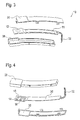
- FIG. 4 shows the components of the electronic module in the direction of viewing from the side of
- FIG. 5 shows a schematic illustration of the overall arrangement of the locking system
- FIG. 6 shows a further possible electrode arrangement
- FIG. 7 shows an alternative exemplary embodiment
- FIG. 8 shows a further possible arrangement of the electrodes in the door handle
- FIGS. 9 and 10 show two embodiments with an intervening 11 shows a flowchart of the electrode arranged on the two electrodes
- An electronic module 10 comprises at least one first electrode 11, whose output signal is fed to a first evaluation unit 14.
- the first evaluation unit 14 generates an unlocking request signal 20.
- a second evaluation unit 16 detects the output signal of the second electrode 12 and converts it into a closing request signal 22.
- the electronic module 10 is a supply voltage 24 and a reference potential 26 is supplied.
- a voltage regulator 18 converts the supply voltage 24 into an internal supply voltage for the first evaluation unit 14 and for the second evaluation unit 16.
- FIG. 2 shows a door outer handle 34 in which the electronic module 10 is integrated.
- the electronic assembly 10 consists of the second electrode 12, which has a circular shape, and a rectangularly shaped first electrode 11.
- the first electrode 11 and the second electrode 12 are arranged at a different height level relative to one another, so that the first electrode 11 in the Near the door handle inside, the second electrode 12, however, is arranged in the vicinity of the door handle outer side in the mounted state.
- a connecting cable 32 is provided for forwarding the Entriegelungs coordinator signal 20 and the Schellerdomainsignals 22 and for supplying the supply voltage 24 as well as the reference potential 26, a connecting cable 32 is provided.
- the two electrodes 11, 12 are enclosed by a housing which is formed from an upper housing part 30 and a lower housing part 28.
- first evaluation unit 14, the second evaluation unit 16 and the voltage regulator 18 are arranged on an opposite side to the second electrode 12.
- the upper housing part 30 as well as the lower housing part 28 can be seen from a perspective opposite to Figure 3 perspective.
- FIG. 5 shows the schematic representation of an overall arrangement.
- the electronics assembly 10 is integrated with the exterior door handle 34.
- the electronic module 10 is connected to a control unit 46 in connection.
- a transmitter / receiver 44 is arranged, which exchanges authorization data with a transponder 42 that can be carried by a user.
- the control unit 46 controls a closing device 48 of the motor vehicle 40 and optionally contains corresponding Feedback signals on the state of the locking device 48th
- a ground electrode 50 which is connected to ground 52 as a reference potential, is arranged between the first and second electrodes 11, 12.
- the ground electrode 50 shields the field of the first electrode 11 represented by the field lines 54 from the second electrode 12.
- the output signals of the first and second electrodes 11, 12 are supplied to a switching means 56, which only forwards one of the two to an evaluation unit 58.
- the evaluation unit 58 controls the switching means 56 in response to an input signal 60.
- the evaluation unit 58 generates an unlocking request signal 20 or a closing request signal 22.
- a ground electrode 50 is arranged between both electrodes 11, 12 for clear separation and mutual shielding of the sensor signals of first and second electrodes 11, 12.
- the cross section of the ground electrode 50 is T-shaped in such a manner that the transverse part of the ground electrode 50 is between a metallic ornamental cap 62 or decorative coating of the door handle 34 and the two electrodes 11, 12 and serves the shield. Crosstalk between the two sensors 11, 12 is thereby prevented.
- FIG. 9 the upper arrangement of FIG. 8 is now modified such that the ornamental cap 62 or the metallic decorative coating is in the same way as the ground electrode 50 electrically contacted with the mass 52. This measure improves the separation of the detection regions of the two electrodes 11, 12.
- the structure selected in FIG. 10 essentially corresponds to that of FIG. 8. Again, the T-shaped ground electrode 52 is also used to shield the two electrodes 11, 12 from each other and from the ornamental cap 62.
- the two electrodes 11, 12 are each parts of an arrangement whose capacitance changes significantly when a user approaches. If the capacity change exceeds a certain limit value, it is concluded that a user is present.
- the respective evaluation units 14, 16 are provided.
- the first electrode 11 is preferably arranged in the side of the exterior door handle 34 facing the motor vehicle 40.
- the approaching hand of the user causes a capacitance change of the first electrode 11 comprehensive arrangement. If the capacitance change exceeds a certain limit value, the first evaluation unit 14 generates an unlocking request signal 20, which is forwarded via the connection cable 32 to the control unit 46.
- the controller 46 then initiates an authorization request.
- a user must prove himself authorized by means of a transponder 42. In this case, the transmitter 44 sends a question signal to the transponder 42, which calculates a response signal therefrom and sends it back to the receiver 44. If the response signal returned by the transponder 42 coincides with a response signal calculated by the control unit 46, an authorized user is concluded.
- the control unit 46 generates an opening command for the locking device 48.
- the motor vehicle 40 is unlocked. If, however, the expected response signal does not match the received response signal, the user is not granted access to the motor vehicle 40.
- the locking device 48 remains in the locked state.
- the second evaluation unit 16 recognizes, based on the change in capacitance, a user located in the vicinity of the second electrode 12. Then a closing request signal 22 is generated and forwarded via the connecting cable 32 to the control unit 46. Either the control unit 46 repeats the authorization procedure, as it was escaped when unlocking the motor vehicle 40, or a closing command is immediately forwarded to the locking device 48.
- the control unit 46 evaluates only the signal which would lead to a change in the closing state of the closing device 48.
- the state of the locking device 48 is known to the control unit 46 via the corresponding feedback signals of the locking device 48.
- a voltage regulator 18 which generates from the battery voltage, that is to say the supply voltage 24, an internal voltage of, for example, 5 V supplying the two evaluation units 14, 16. It could also be provided for each of the evaluation units 14, 16 separate voltage regulator 18, which are each independently activatable. A control signal activating or deactivating the voltage regulator 18 could be coded via an additional cable or on an existing cable, such as the supply voltage 24, are transmitted.
- the two evaluation units 14, 16 can differ in terms of their quiescent power requirement, with respect to their sensitivity or the Anschgeschwindikeit so as to adapt to the particular situation (opening, closing) to achieve. In particular, it may be provided to activate or deactivate the respective evaluation unit 14, 16 or to put it into a standby mode as a function of the state of the closing device 48. If the motor vehicle 40 is locked, for example, then only a release request can be expected, which can only be triggered via the first electrode 11. Thus, the second evaluation unit, which could only lead to the generation of a closing request signal 22 for locking the motor vehicle 40, be deactivated. The second evaluation unit 16 could, for example, only be activated if, after deactivation of the motor vehicle 40, an opening and closing of the driver's door were preceded. As a result, the quiescent power consumption of the overall arrangement can be reduced.
- the first electrode 11 is preferably rectangular in shape to substantially coincide with the expected gripping area of the user's hand.
- the second electrode 12 for detecting a closing desire is circular or elliptical in shape, and in particular dimensioned so that it reliably detects the approach of a finger, for example the thumb.
- different electrode shapes take account of the different operating processes.
- electrodes 11, 12, for example, printed conductors of the electronic assembly 10 are used.
- the printed circuit board 36, on which the electrodes 11, 12 and the two evaluation units 14, 16 and the voltage regulator 18th are arranged, is enclosed by a housing which consists of upper housing part 30 and lower housing part 28. About a recess, the connecting cable 32 is guided to the vehicle interior.
- the two electrodes 11, 12 are functionally separated by a ground electrode 50 introduced between the two electrodes 11, 12.
- the field associated with the first electrode 11, illustrated by means of the field lines 54 does not pass further than the ground electrode 50, so that the second electrode 12 does not detect a field which was influenced by the approach of a user to the first electrode 11.
- the separation of the two electrodes 11, 12 from each other could be realized for example by a so-called multi-layer printed circuit board 36.
- only one evaluation unit 58 is provided for the two electrodes 11, 12.
- the switching means 56 ensures that either the output signal of the first electrode 11 or the output signal of the second electrode 12 of the evaluation unit 58 is provided.
- the switching means 56 is controlled so that always the output signal of those electrode 11, 12 is evaluated, the proximity detection would lead to a change in the state of the locking system 48.
- the switching means 56 forwards the output signal of the first electrode 11, in the unlocked state that of the second electrode 12 on.
- the corresponding information of the locking state of the locking system 48 passes via the input signal 60 to the evaluation unit 58, which converts it into the corresponding control of the switching means 56.
- Switching means 56 and evaluation unit 58 could be combined to form a structural unit.
- the control of the switching means 56 could also directly through the input signal 60 are effected. Thanks to the described arrangement, the component cost can be further reduced.
- FIGS. 8 to 10 ensure improved decoupling of the first and second electrodes 11, 12 even in the case of a spatially close structure of the sensor electrodes 11, 12.
- disturbing influences of design elements on the door handle 34 such as, for example, electrically conductive chrome panels, chrome covers or decorative coatings, are also reduced.
- a crosstalk between the two electrodes 11, 12 can be prevented by the two electrodes 11, 12 are polled coordinated.
- This is inventively achieved in that between the first and second electrode 11, 12 connected to ground 52 as a possible reference potential ground electrode 50 is arranged.
- the ground electrode 50 is also arranged between these design elements 62 and the two electrodes 11, 12.
- the design elements 62 themselves may be electrically connected to ground 52.
- a change to the idle state 101 takes place only when the sensors 11, 12 deliver no opening signal and no closing signal.
- the state 103 is only reached from the idle state 101 when a closing signal is detected.
- the closing request signal 22 is output.
- the change to the idle state 101 takes place only when no closing signal and no opening signal are detected. This processing could also be carried out in the vehicle-mounted control unit.
- the electrodes 11, 12 may be part of a multilayer board, which also contains, for example, the evaluation units 14, 16.
Landscapes
- Engineering & Computer Science (AREA)
- Mechanical Engineering (AREA)
- Lock And Its Accessories (AREA)
Abstract
Claims (15)
- Dispositif d'initialisation d'un processus d'ouverture et de verrouillage d'un véhicule automobile, comprenant un premier capteur d'approche (11, 14) qui génère un signal de demande de déverrouillage (20) pour initialiser un processus d'ouverture d'un système de fermeture (46, 48) d'un véhicule automobile (40) lorsqu'un utilisateur s'approche du premier capteur d'approche (11, 14), et un deuxième capteur d'approche (12, 16) qui génère un signal de demande de fermeture (22) pour initialiser un processus de verrouillage du système de fermeture (46, 48) du véhicule automobile (40) lorsqu'un utilisateur s'approche du deuxième capteur d'approche (12, 16), les premier et deuxième capteurs d'approche (11, 14, 12, 16) comprenant au moins une première ou une deuxième électrode (11, 12) pour reconnaître une approche par une exploitation capacitive,
caractérisé en ce que
pour le blindage, une électrode de potentiel de référence (50) reliée à un potentiel de référence (52) est disposée entre les première et deuxième électrodes (11, 12). - Dispositif selon la revendication 1,
caractérisé en ce que
le premier et/ou le deuxième capteur d'approche (11, 14, 12, 16) est (sont) dans une poignée de portière extérieure (34). - Dispositif selon l'une quelconque des revendications précédentes,
caractérisé en ce que
le premier capteur d'approche (11, 14) est sur la face de la poignée de portière extérieure (34) tournée vers le véhicule automobile (40). - Dispositif selon l'une quelconque des revendications précédentes,
caractérisé en ce que
le deuxième capteur d'approche (12, 16) est sur la face de la poignée de portière extérieure opposée au véhicule automobile (40). - Dispositif selon l'une quelconque des revendications précédentes,
caractérisé en ce que
les premier et deuxième capteurs d'approche (11, 14, 12, 16) sont sur une carte de circuits imprimés commune. - Dispositif selon l'une quelconque des revendications précédentes,
caractérisé en ce qu'
une alimentation en tension (18) est prévue pour alimenter la première et/ou la deuxième unité d'exploitation (14, 16). - Dispositif selon l'une quelconque des revendications précédentes,
caractérisé en ce que
les première et deuxième électrodes (11, 12), la première et/ou la deuxième unité d'exploitation (14, 16) et l'alimentation en tension (18) sont dans un boîtier (28, 30). - Dispositif selon l'une quelconque des revendications précédentes,
caractérisé en ce que
l'apparition du signal de demande de déverrouillage (20) et/ ou du signal de demande de fermeture (22) déclenche une interrogation d'autorisation avec un transpondeur (42) porté par l'utilisateur. - Dispositif selon l'une quelconque des revendications précédentes,
caractérisé en ce que
l'exploitation du signal de la première électrode (11) et/ou la génération d'un signal de demande de déverrouillage (22) ne s'effectue que si le système de fermeture (48) est verrouillé. - Dispositif selon l'une quelconque des revendications précédentes,
caractérisé en ce qu'
au moins un moyen de commutation (56) transmet soit le signal de sortie de la première électrode (11) soit le signal de sortie de la deuxième électrode (12) à une unité d'exploitation (58). - Dispositif selon l'une quelconque des revendications précédentes,
caractérisé en ce que
le moyen de commutation (56) est commandé en fonction de l'état du système de fermeture (48). - Dispositif selon l'une quelconque des revendications précédentes,
caractérisé en ce que
l'électrode de potentiel de référence (50) est disposée entre la première et/ou la deuxième électrode (11, 12) et une couche (62) électriquement conductrice de la poignée de portière extérieure (34). - Dispositif selon l'une quelconque des revendications précédentes,
caractérisé en ce que
les première et deuxième électrodes (11, 12) sont commandées de façon décalée dans le temps. - Dispositif selon l'une quelconque des revendications précédentes,
caractérisé en ce que
lors du déclenchement des première et deuxième électrodes (11, 12), seul le signal de l'électrode (11, 12) qui a été déclenché le premier est transmis. - Dispositif selon l'une quelconque des revendications précédentes,
caractérisé en ce qu'
un nouveau signal de l'électrode (11, 12) n'est transmis que si aucune approche n'a été reconnue au préalable par les deux électrodes (11, 12).
Applications Claiming Priority (3)
| Application Number | Priority Date | Filing Date | Title |
|---|---|---|---|
| DE10051055 | 2000-10-14 | ||
| DE10051055A DE10051055A1 (de) | 2000-10-14 | 2000-10-14 | Vorrichtung zum Einleiten eines Öffnungs- und Verriegelungsvorgangs eines Kraftfahrzeugs |
| PCT/DE2001/003907 WO2002033203A1 (fr) | 2000-10-14 | 2001-10-11 | Dispositif pour l'initialisation d'un processus d'ouverture et de verrouillage d'un vehicule automobile |
Publications (2)
| Publication Number | Publication Date |
|---|---|
| EP1328695A1 EP1328695A1 (fr) | 2003-07-23 |
| EP1328695B1 true EP1328695B1 (fr) | 2006-10-11 |
Family
ID=7659847
Family Applications (1)
| Application Number | Title | Priority Date | Filing Date |
|---|---|---|---|
| EP01987836A Expired - Lifetime EP1328695B1 (fr) | 2000-10-14 | 2001-10-11 | Dispositif pour l'initialisation d'un processus d'ouverture et de verrouillage d'un vehicule automobile |
Country Status (6)
| Country | Link |
|---|---|
| US (1) | US6847289B2 (fr) |
| EP (1) | EP1328695B1 (fr) |
| KR (1) | KR100817426B1 (fr) |
| AU (1) | AU2002218132A1 (fr) |
| DE (3) | DE10051055A1 (fr) |
| WO (1) | WO2002033203A1 (fr) |
Families Citing this family (130)
| Publication number | Priority date | Publication date | Assignee | Title |
|---|---|---|---|---|
| FR2817581B1 (fr) † | 2000-12-01 | 2006-08-25 | Valeo Electronique | Poignee d'ouvrant de vehicule comprenant un capteur d'approche et un capteur tactile cooperant avec un systeme d'acces mains libres |
| JP3614789B2 (ja) | 2001-03-28 | 2005-01-26 | 株式会社ホンダロック | 車両のアウトハンドル装置 |
| DE10132925A1 (de) * | 2001-06-12 | 2003-01-02 | Bosch Gmbh Robert | Türaussengriffanordnung |
| FR2828225B1 (fr) * | 2001-08-01 | 2003-10-31 | Valeo Electronique | Poignee d'ouvrant pour vehicule automobile |
| FR2830110B1 (fr) * | 2001-09-27 | 2004-10-08 | Valeo Electronique | Capteur de presence destine a etre integre dans une poignee d'un ouvrant de vehicule automobile |
| DE10204025B4 (de) * | 2002-01-31 | 2017-10-05 | Huf Hülsbeck & Fürst Gmbh & Co. Kg | Kombinierte Sicherheits-/Betätigungseinrichtung |
| DE10221511B4 (de) * | 2002-05-14 | 2013-09-05 | Huf Hülsbeck & Fürst Gmbh & Co. Kg | Schlüssellose Sicherheits-/Betätigungseinrichtung für Kraftfahrzeuge |
| DE10262353B4 (de) * | 2002-05-14 | 2015-02-26 | Huf Electronics Gmbh | Schlüssellose Sicherheits-/Betätigungseinrichtung für Kraftfahrzeuge |
| WO2004007879A1 (fr) * | 2002-06-20 | 2004-01-22 | Schaffner Emv Ag | Circuit de commande electronique comprenant un emetteur pour systeme de fermeture de portiere de vehicule |
| DE10232244B4 (de) * | 2002-07-17 | 2005-03-10 | Huf Huelsbeck & Fuerst Gmbh | Schließsystem für eine Tür, Klappe o. dgl., insbesondere bei Fahrzeugen |
| FR2842853B1 (fr) * | 2002-07-23 | 2005-02-04 | Valeo Electronique | Capteur de presence pour poignee d'ouvrant, notamment pour vehicule automobile |
| JP3770218B2 (ja) | 2002-08-29 | 2006-04-26 | アイシン精機株式会社 | 車両用ドア開扉用人体検出装置及びその使用方法 |
| DE10240850A1 (de) * | 2002-09-04 | 2004-03-18 | Delphi Technologies, Inc., Troy | Schließsystem |
| DE10253503B4 (de) * | 2002-11-16 | 2012-12-06 | Robert Bosch Gmbh | Kapazitiver Sensor und Türgriffeinheit |
| DE10255439B4 (de) * | 2002-11-28 | 2008-07-17 | Daimler Ag | Griffanordnung für eine Fahrzeugtür |
| DE10258392A1 (de) * | 2002-12-12 | 2004-06-24 | Kiekert Ag | Türgriffanordnung für eine Kraftfahrzeugtür |
| DE10259124A1 (de) * | 2002-12-18 | 2004-07-01 | Nexans | Anordnung zur Signalübertragung zwischen einem Sender und einer Steuereinheit |
| DE10300573A1 (de) * | 2003-01-10 | 2004-07-22 | Daimlerchrysler Ag | Vorrichtung zum Ver-und Entriegeln einer Fahrzeugtür |
| JP2004219311A (ja) * | 2003-01-16 | 2004-08-05 | Omron Corp | 静電容量センサ及び開閉体挟み込み検知装置 |
| JP2004232300A (ja) * | 2003-01-29 | 2004-08-19 | Aisin Seiki Co Ltd | アウトサイドハンドル装置 |
| FR2853346B1 (fr) * | 2003-04-01 | 2005-06-24 | Peugeot Citroen Automobiles Sa | Procede de limitation d'un effet de rebond d'un dispositif de verrouillage et de deverrouillage d'une serrure d'une porte d'un vehicule automobile |
| US7026861B2 (en) * | 2003-04-22 | 2006-04-11 | Touchsensor Technologies Llc | Electronic door latch system with water rejection filtering |
| GB2421799B (en) * | 2003-06-20 | 2006-11-15 | Honda Lock Kk | Vehicle door outer handle system |
| DE10336335B4 (de) * | 2003-08-08 | 2015-03-12 | Huf Hülsbeck & Fürst Gmbh & Co. Kg | Schließvorrichtung für Fahrzeuge |
| DE10340601A1 (de) | 2003-09-01 | 2005-04-07 | Kiekert Ag | Betätigungseinrichtung für ein Kraftfahrzeug-Schließsystem und Verfahren zur Anzeige eines Betriebszustands |
| DE10341402A1 (de) * | 2003-09-05 | 2005-04-07 | Brose Schließsysteme GmbH & Co.KG | Kraftfahrzeug-Türschließsystem und Türinnengriff |
| JP4098215B2 (ja) * | 2003-10-29 | 2008-06-11 | アイシン精機株式会社 | 車両用人体検出装置 |
| EP1582670B1 (fr) * | 2004-03-30 | 2010-06-16 | Kabushiki Kaisha Honda Lock | Dispositif de poignée pour porte de véhicule |
| JP4041090B2 (ja) * | 2004-04-06 | 2008-01-30 | 本田技研工業株式会社 | 車両用遠隔施錠解錠制御装置 |
| FR2873473B1 (fr) * | 2004-07-23 | 2006-09-08 | Siemens Vdo Automotive Sas | Procede et dispositif de gestion de la consommation d'energie d'un capteur de proximite d'un dispositif de controle d'acces a un habitacle de vehicule automobile |
| DE102004038569B3 (de) * | 2004-08-06 | 2005-10-20 | Huf Huelsbeck & Fuerst Gmbh | Kraftfahrzeugtürgriff |
| DE102004054985A1 (de) * | 2004-11-13 | 2006-06-01 | Hella Kgaa Hueck & Co. | Anordnung aus einem elektronischen Bauelement und einem flexiblen Schaltungsträger |
| DE112005003178T5 (de) | 2004-12-17 | 2008-02-14 | Stoneridge Control Devices, Inc., Canton | Berührungssensorvorrichtung und Verfahren |
| DE102005017451A1 (de) | 2005-04-15 | 2006-10-19 | Hella Kgaa Hueck & Co. | Türgriff für Kraftfahrzeuge mit einem kapazitiven Näherungssensor |
| DE102005031441A1 (de) * | 2005-07-04 | 2007-01-11 | Huf Hülsbeck & Fürst Gmbh & Co. Kg | Griffvorrichtung |
| DE602007000993D1 (de) * | 2006-03-16 | 2009-06-10 | Aisin Seiki | Türgriffvorrichtung für Fahrzeuge |
| DE102006013027B4 (de) * | 2006-03-20 | 2008-03-20 | SCHÜCO International KG | Griffelement |
| DE102006025075A1 (de) * | 2006-05-30 | 2007-12-06 | Hella Kgaa Hueck & Co. | Kapazitive Sensoreinrichtung |
| DE102006035223A1 (de) * | 2006-07-26 | 2008-02-07 | Huf Hülsbeck & Fürst Gmbh & Co. Kg | Schließsystem für Fahrzeuge |
| JP4947348B2 (ja) * | 2006-09-13 | 2012-06-06 | アイシン精機株式会社 | 車両用ドアハンドル装置 |
| WO2008137634A1 (fr) | 2007-05-03 | 2008-11-13 | Donnelly Corporation | Module d'éclairage pour un véhicule |
| JP4751860B2 (ja) * | 2007-07-27 | 2011-08-17 | アイシン精機株式会社 | ドアハンドル装置 |
| US8022808B2 (en) * | 2007-10-01 | 2011-09-20 | Denso International America, Inc. | Vehicle power door control with passive entry |
| FR2927108B1 (fr) * | 2008-02-06 | 2013-03-08 | Continental Automotive France | Dispositif de detection de toucher d'une poignee de porte de vehicule automobile |
| EP2252753B1 (fr) * | 2008-03-13 | 2012-07-25 | Huf Hülsbeck & Fürst GmbH & Co. KG | Poignée extérieure de portière de véhicule équipée d un module de détection |
| DE102008016284A1 (de) * | 2008-03-28 | 2009-10-08 | Lic Langmatz Gmbh | Vorrichtung zum Auslösen eines Schaltvorgangs insbesondere Anforderungsgerät für eine Verkehrsampel |
| US8098130B2 (en) * | 2008-06-11 | 2012-01-17 | Flextronics Automotive Inc. | System and method for activating electromechanical systems using flexible intelligent radio frequency modules |
| US20100007463A1 (en) * | 2008-07-09 | 2010-01-14 | Magna Mirrors Of America, Inc. | Vehicle handle with control circuitry |
| KR100974550B1 (ko) * | 2008-07-15 | 2010-08-11 | 현대자동차주식회사 | 차량의 도어 잠금장치 제어 시스템 |
| US20100088855A1 (en) * | 2008-10-14 | 2010-04-15 | Magna Mirrors Of America, Inc. | Vehicle door handle assembly |
| US9260882B2 (en) | 2009-03-12 | 2016-02-16 | Ford Global Technologies, Llc | Universal global latch system |
| DE102009002566A1 (de) * | 2009-04-22 | 2010-10-28 | Huf Hülsbeck & Fürst Gmbh & Co. Kg | Sensorelektronik in einem Kraftfahrzeugtürgriff |
| DE102009037497B4 (de) | 2009-08-13 | 2012-04-12 | Predrag Stevanovic | Diagnosevorrichtung für schlüsselloses Zugangssystem |
| DE202009017298U1 (de) * | 2009-12-18 | 2011-04-28 | BROSE SCHLIEßSYSTEME GMBH & CO. KG | Kraftfahrzeugschlossanordnung |
| US9080355B2 (en) * | 2009-12-18 | 2015-07-14 | Brose Schliesssysteme Gmbh & Co. Kg | Circuit and method for preventing inadvertent opening of a vehicle door |
| US8786401B2 (en) | 2009-12-23 | 2014-07-22 | Magna Mirrors Of America, Inc. | Extendable flush door handle for vehicle |
| DE102010002282A1 (de) * | 2010-02-24 | 2011-08-25 | Lisa Dräxlmaier GmbH, 84137 | Innenausstattungsteil sowie Außenverkleidungsteil eines Fahrezeugs mit einem Ultraschallsensor |
| DE102010019362A1 (de) * | 2010-05-05 | 2011-11-10 | Volkswagen Ag | Bedienverfahren und Bedienvorrichtung für ein Fahrzeug |
| US10576896B2 (en) | 2010-10-01 | 2020-03-03 | Magna Mirrors Of America, Inc. | Vehicle exterior mirror system with light module |
| US8764256B2 (en) | 2010-10-01 | 2014-07-01 | Magna Mirrors Of America, Inc. | Vehicle exterior mirror system with light module |
| DE102010060364A1 (de) | 2010-11-04 | 2012-05-10 | Huf Hülsbeck & Fürst Gmbh & Co. Kg | Verfahren für ein Kraftfahrzeug |
| DE102011012688A1 (de) * | 2011-03-01 | 2012-09-06 | Brose Fahrzeugteile Gmbh & Co. Kommanditgesellschaft, Hallstadt | Türgriffeinheit für ein Fahrzeug |
| DE102011103406B4 (de) * | 2011-06-06 | 2015-03-26 | Brose Fahrzeugteile Gmbh & Co. Kommanditgesellschaft, Hallstadt | Stellvorrichtung für ein Fahrzeug |
| FR2978836B1 (fr) * | 2011-08-03 | 2013-09-06 | Continental Automotive France | Dispositif de detection d'approche et/ou de contact, procede et poignee de portiere de vehicule associes |
| US9143126B2 (en) | 2011-09-22 | 2015-09-22 | Ford Global Technologies, Llc | Proximity switch having lockout control for controlling movable panel |
| US9551166B2 (en) | 2011-11-02 | 2017-01-24 | Ford Global Technologies, Llc | Electronic interior door release system |
| US10112556B2 (en) | 2011-11-03 | 2018-10-30 | Ford Global Technologies, Llc | Proximity switch having wrong touch adaptive learning and method |
| US8994228B2 (en) | 2011-11-03 | 2015-03-31 | Ford Global Technologies, Llc | Proximity switch having wrong touch feedback |
| US9065447B2 (en) | 2012-04-11 | 2015-06-23 | Ford Global Technologies, Llc | Proximity switch assembly and method having adaptive time delay |
| US9520875B2 (en) | 2012-04-11 | 2016-12-13 | Ford Global Technologies, Llc | Pliable proximity switch assembly and activation method |
| US9531379B2 (en) | 2012-04-11 | 2016-12-27 | Ford Global Technologies, Llc | Proximity switch assembly having groove between adjacent proximity sensors |
| US9944237B2 (en) | 2012-04-11 | 2018-04-17 | Ford Global Technologies, Llc | Proximity switch assembly with signal drift rejection and method |
| US9184745B2 (en) | 2012-04-11 | 2015-11-10 | Ford Global Technologies, Llc | Proximity switch assembly and method of sensing user input based on signal rate of change |
| US9559688B2 (en) | 2012-04-11 | 2017-01-31 | Ford Global Technologies, Llc | Proximity switch assembly having pliable surface and depression |
| US9219472B2 (en) | 2012-04-11 | 2015-12-22 | Ford Global Technologies, Llc | Proximity switch assembly and activation method using rate monitoring |
| US9287864B2 (en) | 2012-04-11 | 2016-03-15 | Ford Global Technologies, Llc | Proximity switch assembly and calibration method therefor |
| US8933708B2 (en) | 2012-04-11 | 2015-01-13 | Ford Global Technologies, Llc | Proximity switch assembly and activation method with exploration mode |
| US9831870B2 (en) | 2012-04-11 | 2017-11-28 | Ford Global Technologies, Llc | Proximity switch assembly and method of tuning same |
| US9568527B2 (en) | 2012-04-11 | 2017-02-14 | Ford Global Technologies, Llc | Proximity switch assembly and activation method having virtual button mode |
| US9197206B2 (en) | 2012-04-11 | 2015-11-24 | Ford Global Technologies, Llc | Proximity switch having differential contact surface |
| US9660644B2 (en) | 2012-04-11 | 2017-05-23 | Ford Global Technologies, Llc | Proximity switch assembly and activation method |
| US9136840B2 (en) | 2012-05-17 | 2015-09-15 | Ford Global Technologies, Llc | Proximity switch assembly having dynamic tuned threshold |
| US8981602B2 (en) | 2012-05-29 | 2015-03-17 | Ford Global Technologies, Llc | Proximity switch assembly having non-switch contact and method |
| US9337832B2 (en) | 2012-06-06 | 2016-05-10 | Ford Global Technologies, Llc | Proximity switch and method of adjusting sensitivity therefor |
| US9641172B2 (en) | 2012-06-27 | 2017-05-02 | Ford Global Technologies, Llc | Proximity switch assembly having varying size electrode fingers |
| FR2993384B1 (fr) * | 2012-07-13 | 2016-11-25 | Continental Automotive France | Dispositif de detection de la presence d'un utilisateur, poignee de portiere comprenant ledit dispositif et procede de configuration de la poignee associee |
| US8872447B2 (en) * | 2012-08-08 | 2014-10-28 | Honda Motor Co., Ltd. | Dual function power door |
| US8922340B2 (en) * | 2012-09-11 | 2014-12-30 | Ford Global Technologies, Llc | Proximity switch based door latch release |
| DE102012109034A1 (de) * | 2012-09-25 | 2014-03-27 | Huf Hülsbeck & Fürst Gmbh & Co. Kg | Kraftfahrzeugtürgriff mit Sensorelektronik |
| DE102013002750A1 (de) * | 2013-02-19 | 2014-08-21 | Huf Hülsbeck & Fürst Gmbh & Co. Kg | Türgriff für ein Kraftfahrzeug |
| US9311204B2 (en) | 2013-03-13 | 2016-04-12 | Ford Global Technologies, Llc | Proximity interface development system having replicator and method |
| US20140292004A1 (en) * | 2013-04-01 | 2014-10-02 | Magna Mirrors Of America, Inc. | Vehicle door handle system |
| DE102013103316A1 (de) * | 2013-04-03 | 2014-10-09 | Dorma Gmbh + Co. Kg | System zur Verriegelung und Entriegelung einer Schiebetür |
| JP5932708B2 (ja) * | 2013-04-22 | 2016-06-08 | 株式会社ホンダロック | 車両用ドアのアウトハンドル装置 |
| US9353557B2 (en) * | 2013-06-12 | 2016-05-31 | Huf North America Automotive Parts Manufacturing Corp. | Door handle arrangement for vehicles |
| DE102013010993A1 (de) * | 2013-07-02 | 2015-01-08 | Brose Fahrzeugteile Gmbh & Co. Kommanditgesellschaft, Hallstadt | Objekterfassungsvorrichtung für ein Fahrzeug |
| US9416565B2 (en) | 2013-11-21 | 2016-08-16 | Ford Global Technologies, Llc | Piezo based energy harvesting for e-latch systems |
| FR3015690B1 (fr) * | 2013-12-19 | 2016-01-29 | Valeo Securite Habitacle | Capteur de presence pour ouvrant de vehicule automobile |
| US9903142B2 (en) | 2014-05-13 | 2018-02-27 | Ford Global Technologies, Llc | Vehicle door handle and powered latch system |
| US10323442B2 (en) | 2014-05-13 | 2019-06-18 | Ford Global Technologies, Llc | Electronic safe door unlatching operations |
| US10119308B2 (en) | 2014-05-13 | 2018-11-06 | Ford Global Technologies, Llc | Powered latch system for vehicle doors and control system therefor |
| US9834964B2 (en) * | 2014-05-13 | 2017-12-05 | Ford Global Technologies, Llc | Powered vehicle door latch and exterior handle with sensor |
| US10273725B2 (en) | 2014-05-13 | 2019-04-30 | Ford Global Technologies, Llc | Customer coaching method for location of E-latch backup handles |
| DE102014107559A1 (de) * | 2014-05-28 | 2015-12-03 | Huf Hülsbeck & Fürst Gmbh & Co. Kg | Sensoreinrichtung für ein Kraftfahrzeug |
| US10047548B2 (en) * | 2014-06-17 | 2018-08-14 | Magna Closures Inc. | Latch assembly for latch operation of closure panels for vehicles |
| US9909344B2 (en) | 2014-08-26 | 2018-03-06 | Ford Global Technologies, Llc | Keyless vehicle door latch system with powered backup unlock feature |
| DE102014113832A1 (de) * | 2014-09-24 | 2016-03-24 | Huf Hülsbeck & Fürst Gmbh & Co. Kg | Daten- und Messerfassungsvorrichtung für einen Türgriff sowie Verfahren dazu |
| US10038443B2 (en) | 2014-10-20 | 2018-07-31 | Ford Global Technologies, Llc | Directional proximity switch assembly |
| US9654103B2 (en) | 2015-03-18 | 2017-05-16 | Ford Global Technologies, Llc | Proximity switch assembly having haptic feedback and method |
| WO2016174753A1 (fr) * | 2015-04-28 | 2016-11-03 | 三井金属アクト株式会社 | Dispositif de verrouillage de porte d'automobile |
| US9548733B2 (en) | 2015-05-20 | 2017-01-17 | Ford Global Technologies, Llc | Proximity sensor assembly having interleaved electrode configuration |
| US10118594B2 (en) | 2015-08-21 | 2018-11-06 | Honda Motor Co., Ltd. | System and method for reducing power consumption for a smart entry door handle in a vehicle |
| US9725069B2 (en) | 2015-10-12 | 2017-08-08 | Ford Global Technologies, Llc | Keyless vehicle systems |
| DE102016110345A1 (de) * | 2016-06-03 | 2017-12-07 | Huf Hülsbeck & Fürst Gmbh & Co. Kg | Zusätzliches Türgriffmodul für eine Türgriffeinheit |
| US10550610B2 (en) | 2016-06-22 | 2020-02-04 | Ford Global Technologies, Llc | Inside override emergency handle for door release |
| DE102016212527B4 (de) | 2016-07-08 | 2019-08-08 | Magna Mirrors Holding Gmbh | Blinkeinheit für einen Außenspiegel |
| US10227810B2 (en) | 2016-08-03 | 2019-03-12 | Ford Global Technologies, Llc | Priority driven power side door open/close operations |
| US10087671B2 (en) | 2016-08-04 | 2018-10-02 | Ford Global Technologies, Llc | Powered driven door presenter for vehicle doors |
| US10329823B2 (en) | 2016-08-24 | 2019-06-25 | Ford Global Technologies, Llc | Anti-pinch control system for powered vehicle doors |
| US10458171B2 (en) | 2016-09-19 | 2019-10-29 | Ford Global Technologies, Llc | Anti-pinch logic for door opening actuator |
| DE102016219748A1 (de) * | 2016-10-11 | 2018-04-12 | Zf Friedrichshafen Ag | Sensorvorrichtung für einen Türgriff für ein Fahrzeug, Türgriff und Verfahren zum Herstellen einer Sensorvorrichtung |
| US10045184B2 (en) | 2016-11-11 | 2018-08-07 | Carnival Corporation | Wireless guest engagement system |
| US10499228B2 (en) | 2016-11-11 | 2019-12-03 | Carnival Corporation | Wireless guest engagement system |
| US11671807B2 (en) * | 2016-11-11 | 2023-06-06 | Carnival Corporation | Wireless device and methods for making and using the same |
| US10604970B2 (en) | 2017-05-04 | 2020-03-31 | Ford Global Technologies, Llc | Method to detect end-of-life in latches |
| US10907386B2 (en) | 2018-06-07 | 2021-02-02 | Ford Global Technologies, Llc | Side door pushbutton releases |
| CN113700399B (zh) | 2018-12-19 | 2023-05-09 | 麦格纳覆盖件有限公司 | 致动器和用于车辆的门的车门致动系统 |
| DE102019132134A1 (de) * | 2019-11-27 | 2021-05-27 | Huf Hülsbeck & Fürst Gmbh & Co. Kg | Vorrichtung für ein Fahrzeug zur Detektion einer Aktivierungshandlung in einem Detektionsbereich |
| DE102019132136A1 (de) | 2019-11-27 | 2021-05-27 | Huf Hülsbeck & Fürst Gmbh & Co. Kg | Vorrichtung für ein Fahrzeug zur Detektion einer Aktivierungshandlung in mindestens zwei unterschiedlichen Detektionsbereichen |
| DE102020131516B4 (de) | 2020-11-27 | 2025-09-18 | Emz-Hanauer Gmbh & Co. Kgaa | Elektrisches Haushaltsgerät mit Näherungs-Bedienelement mit überlappenden Sensorelektroden |
Family Cites Families (17)
| Publication number | Priority date | Publication date | Assignee | Title |
|---|---|---|---|---|
| JPS6237479A (ja) * | 1985-08-12 | 1987-02-18 | 日産自動車株式会社 | 無線式施解錠制御装置 |
| DE3536377A1 (de) * | 1985-10-11 | 1987-04-16 | Bayerische Motoren Werke Ag | Sicherheitseinrichtung fuer kraftfahrzeuge |
| US4942393A (en) * | 1988-05-27 | 1990-07-17 | Lectron Products, Inc. | Passive keyless entry system |
| DE9012968U1 (de) * | 1990-09-11 | 1990-11-15 | Siemens AG, 8000 München | Verriegelungsanlage für eine Tür an einem Kraftfahrzeug |
| DE4212291C2 (de) * | 1992-04-11 | 1994-08-04 | Daimler Benz Ag | Anordnung eines berührungslos beeinflußbaren Schaltelements |
| DE9415257U1 (de) * | 1994-09-20 | 1994-11-17 | Siemens AG, 80333 München | Näherungsschalter mit drei Schaltpositionen |
| US5973611A (en) | 1995-03-27 | 1999-10-26 | Ut Automotive Dearborn, Inc. | Hands-free remote entry system |
| DE19744152A1 (de) * | 1997-10-07 | 1999-04-29 | Ifm Electronic Gmbh | Schaltungsanordnung zur Erfassung der Kapazität bzw. einer Kapazitätsänderung eines kapazitiven Schaltungs- oder Bauelementes |
| DE19617038C2 (de) * | 1996-04-27 | 2000-11-30 | Huf Huelsbeck & Fuerst Gmbh | Schließsystem, insbesondere für Kraftfahrzeuge |
| DE19620059B4 (de) * | 1996-05-20 | 2004-12-23 | Ifm Electronic Gmbh | Schaltungsanordnung zum Entriegeln mindestens eines Türschlosses eines Kraftfahrzeugs |
| DE19805659C1 (de) * | 1998-02-12 | 1999-03-18 | Bosch Gmbh Robert | Vorrichtung zum Auslösen einer Berechtigungsabfrage für ein Fahrzeug |
| AUPP277798A0 (en) * | 1998-04-03 | 1998-04-30 | Robert Bosch Gmbh | Detection system |
| US6034617A (en) * | 1998-12-04 | 2000-03-07 | Eaton Corporation | Operator intent based passive keyless vehicle control system |
| EP1238177B2 (fr) * | 1999-11-29 | 2009-03-25 | Brose Schliesssysteme GmbH & Co. KG | Dispositif de poignee exterieure de porte |
| US6583715B1 (en) * | 2000-02-28 | 2003-06-24 | Lear Corporation | Method and system for unlocking and/or opening at least one openable member of a motor vehicle |
| US6825752B2 (en) * | 2000-06-13 | 2004-11-30 | Siemens Vdo Automotive Corporation | Effortless entry system and method |
| US20010054952A1 (en) * | 2000-06-21 | 2001-12-27 | Desai Tejas B. | Automatic port operation |
-
2000
- 2000-10-14 DE DE10051055A patent/DE10051055A1/de not_active Withdrawn
-
2001
- 2001-10-11 WO PCT/DE2001/003907 patent/WO2002033203A1/fr not_active Ceased
- 2001-10-11 EP EP01987836A patent/EP1328695B1/fr not_active Expired - Lifetime
- 2001-10-11 KR KR1020027007478A patent/KR100817426B1/ko not_active Expired - Lifetime
- 2001-10-11 US US10/149,833 patent/US6847289B2/en not_active Expired - Lifetime
- 2001-10-11 AU AU2002218132A patent/AU2002218132A1/en not_active Abandoned
- 2001-10-11 DE DE50111223T patent/DE50111223D1/de not_active Expired - Lifetime
- 2001-10-11 DE DE10194444T patent/DE10194444D2/de not_active Expired - Lifetime
Also Published As
| Publication number | Publication date |
|---|---|
| WO2002033203A1 (fr) | 2002-04-25 |
| DE10194444D2 (de) | 2003-09-11 |
| US20030107473A1 (en) | 2003-06-12 |
| DE50111223D1 (de) | 2006-11-23 |
| US6847289B2 (en) | 2005-01-25 |
| EP1328695A1 (fr) | 2003-07-23 |
| AU2002218132A1 (en) | 2002-04-29 |
| KR20020063589A (ko) | 2002-08-03 |
| DE10051055A1 (de) | 2002-05-02 |
| KR100817426B1 (ko) | 2008-03-27 |
Similar Documents
| Publication | Publication Date | Title |
|---|---|---|
| EP1328695B1 (fr) | Dispositif pour l'initialisation d'un processus d'ouverture et de verrouillage d'un vehicule automobile | |
| EP1507943B1 (fr) | Dispositif de securite et d'actionnement sans cle pour des vehicules automobiles | |
| EP1902189B1 (fr) | Systeme de poignee | |
| EP2728093B1 (fr) | Système de sécurité doté d'un capteur de détection d'accident | |
| EP1808344A1 (fr) | Dispositif destiné à la commande d'un verrouillage de porte de véhicule | |
| WO2014146949A1 (fr) | Dispositif de poignée de porte pour véhicule avec capteur de proximité capacitif et unité d'émission/réception nfc | |
| EP1103675A2 (fr) | Système de verrouillage pour porte de véhicule | |
| DE10131896B4 (de) | Kraftfahrzeug-Türschließsystem | |
| DE102019132136A1 (de) | Vorrichtung für ein Fahrzeug zur Detektion einer Aktivierungshandlung in mindestens zwei unterschiedlichen Detektionsbereichen | |
| DE102009005617B4 (de) | Türverriegelungs-Steuerungsvorrichtung | |
| DE10300573A1 (de) | Vorrichtung zum Ver-und Entriegeln einer Fahrzeugtür | |
| EP2007610B1 (fr) | Verrouillage électrique de direction, en particulier pour un vehicule automobile | |
| WO2007003476A1 (fr) | Dispositif de commande intelligent | |
| EP1476623B1 (fr) | Circuit de commande electronique dote d'un capteur de contact destine a un systeme de fermeture d'une portiere de vehicule | |
| EP1584777B1 (fr) | Système de fermeture pour un véhicule et son procédé de fonctionnement | |
| EP2098672A1 (fr) | Véhicule automobile doté d'une pièce de véhicule réglable automatiquement en position ouverte ou fermée | |
| EP0929727B1 (fr) | Dispositif de fermeture | |
| DE10047656A1 (de) | Neuer Schalter für Fernbedienungsanwendungen | |
| DE10004616A1 (de) | Schaltungsanordnung für eine Sende- und/oder Empfangseinrichtung | |
| DE102008062627A1 (de) | System und Verfahren für die entfernte Aktivierung unter Verwendung einer Sender-Schalteranordnung | |
| EP2581277B1 (fr) | Dispositif pour un système de sécurité d'un véhicule automobile avec un système électronique conçu de manière autonome et indépendante par rapport au véhicule | |
| DE10309600A1 (de) | Sicherungssystem | |
| DE102004046903A1 (de) | Vorrichtung zur Auslösung eines Abfragesignals | |
| DE10262353B4 (de) | Schlüssellose Sicherheits-/Betätigungseinrichtung für Kraftfahrzeuge | |
| EP1989084B1 (fr) | Commande |
Legal Events
| Date | Code | Title | Description |
|---|---|---|---|
| PUAI | Public reference made under article 153(3) epc to a published international application that has entered the european phase |
Free format text: ORIGINAL CODE: 0009012 |
|
| 17P | Request for examination filed |
Effective date: 20030514 |
|
| AK | Designated contracting states |
Designated state(s): AT BE CH CY DE DK ES FI FR GB GR IE IT LI LU MC NL PT SE TR |
|
| RBV | Designated contracting states (corrected) |
Designated state(s): DE FR GB IT |
|
| 17Q | First examination report despatched |
Effective date: 20041028 |
|
| GRAP | Despatch of communication of intention to grant a patent |
Free format text: ORIGINAL CODE: EPIDOSNIGR1 |
|
| GRAS | Grant fee paid |
Free format text: ORIGINAL CODE: EPIDOSNIGR3 |
|
| GRAA | (expected) grant |
Free format text: ORIGINAL CODE: 0009210 |
|
| AK | Designated contracting states |
Kind code of ref document: B1 Designated state(s): DE FR GB IT |
|
| REG | Reference to a national code |
Ref country code: GB Ref legal event code: FG4D Free format text: NOT ENGLISH |
|
| REF | Corresponds to: |
Ref document number: 50111223 Country of ref document: DE Date of ref document: 20061123 Kind code of ref document: P |
|
| GBT | Gb: translation of ep patent filed (gb section 77(6)(a)/1977) |
Effective date: 20070116 |
|
| ET | Fr: translation filed | ||
| PLBE | No opposition filed within time limit |
Free format text: ORIGINAL CODE: 0009261 |
|
| STAA | Information on the status of an ep patent application or granted ep patent |
Free format text: STATUS: NO OPPOSITION FILED WITHIN TIME LIMIT |
|
| 26N | No opposition filed |
Effective date: 20070712 |
|
| PGFP | Annual fee paid to national office [announced via postgrant information from national office to epo] |
Ref country code: GB Payment date: 20071022 Year of fee payment: 7 |
|
| GBPC | Gb: european patent ceased through non-payment of renewal fee |
Effective date: 20081011 |
|
| PG25 | Lapsed in a contracting state [announced via postgrant information from national office to epo] |
Ref country code: GB Free format text: LAPSE BECAUSE OF NON-PAYMENT OF DUE FEES Effective date: 20081011 |
|
| REG | Reference to a national code |
Ref country code: FR Ref legal event code: PLFP Year of fee payment: 15 |
|
| REG | Reference to a national code |
Ref country code: FR Ref legal event code: PLFP Year of fee payment: 16 |
|
| REG | Reference to a national code |
Ref country code: FR Ref legal event code: PLFP Year of fee payment: 17 |
|
| REG | Reference to a national code |
Ref country code: FR Ref legal event code: PLFP Year of fee payment: 18 |
|
| PGFP | Annual fee paid to national office [announced via postgrant information from national office to epo] |
Ref country code: IT Payment date: 20201030 Year of fee payment: 20 Ref country code: FR Payment date: 20201020 Year of fee payment: 20 |
|
| PGFP | Annual fee paid to national office [announced via postgrant information from national office to epo] |
Ref country code: DE Payment date: 20201214 Year of fee payment: 20 |
|
| REG | Reference to a national code |
Ref country code: DE Ref legal event code: R071 Ref document number: 50111223 Country of ref document: DE |