EP1329263A1 - Rotor mit Behälteraufnahmen für zu zentrifugierende Produkte und entsprechende Zentrifuge - Google Patents
Rotor mit Behälteraufnahmen für zu zentrifugierende Produkte und entsprechende Zentrifuge Download PDFInfo
- Publication number
- EP1329263A1 EP1329263A1 EP03290034A EP03290034A EP1329263A1 EP 1329263 A1 EP1329263 A1 EP 1329263A1 EP 03290034 A EP03290034 A EP 03290034A EP 03290034 A EP03290034 A EP 03290034A EP 1329263 A1 EP1329263 A1 EP 1329263A1
- Authority
- EP
- European Patent Office
- Prior art keywords
- rotation
- axis
- geometric
- rotor
- housing
- Prior art date
- Legal status (The legal status is an assumption and is not a legal conclusion. Google has not performed a legal analysis and makes no representation as to the accuracy of the status listed.)
- Granted
Links
- 238000013519 translation Methods 0.000 claims abstract description 24
- 230000009466 transformation Effects 0.000 claims abstract description 21
- 230000014616 translation Effects 0.000 description 19
- 238000005119 centrifugation Methods 0.000 description 9
- 239000000047 product Substances 0.000 description 9
- 239000006227 byproduct Substances 0.000 description 3
- 230000000694 effects Effects 0.000 description 1
- 230000008030 elimination Effects 0.000 description 1
- 238000003379 elimination reaction Methods 0.000 description 1
- 230000001788 irregular Effects 0.000 description 1
- 239000002184 metal Substances 0.000 description 1
- 238000005057 refrigeration Methods 0.000 description 1
Images


Classifications
-
- B—PERFORMING OPERATIONS; TRANSPORTING
- B04—CENTRIFUGAL APPARATUS OR MACHINES FOR CARRYING-OUT PHYSICAL OR CHEMICAL PROCESSES
- B04B—CENTRIFUGES
- B04B5/00—Other centrifuges
- B04B5/04—Radial chamber apparatus for separating predominantly liquid mixtures, e.g. butyrometers
- B04B5/0407—Radial chamber apparatus for separating predominantly liquid mixtures, e.g. butyrometers for liquids contained in receptacles
- B04B5/0414—Radial chamber apparatus for separating predominantly liquid mixtures, e.g. butyrometers for liquids contained in receptacles comprising test tubes
Definitions
- the present invention relates to a rotor of the type intended to be driven in rotation about a central axis of rotation and in which a number n of housings for receiving a product to be centrifuged are provided, the housings being eccentric relative to the rotation axis.
- the invention applies, for example, to the centrifugation of products organic.
- housings For centrifugation of such products, generally used tapered rotors in which the housings have been formed in the form of recesses. These housings have elongated shapes and are, for each rotor, regularly distributed around its axis of rotation. These housings are intended to receive, for example, tubes containing the products to be centrifuged and closed with caps.
- a centrifuge using such a rotor generally comprises a tank, provided with refrigeration means and in which the rotor is mounted on a rotating drive head.
- An object of the invention is to solve this problem by limiting the noise pollution caused by rotating rotors of the type supra.
- the subject of the invention is a rotor of the aforementioned type, characterized in that the geometric image of at least one first housing, by a geometric rotation around the axis of rotation in a first direction of rotation and angle 360 ° / n , is distinct from a second housing which directly follows the first housing in the first direction of rotation.
- the invention further relates to a centrifuge comprising a tank, a rotor intended to be placed in the tank, and means rotor rotation drive, characterized in that the rotor is a rotor as defined above.
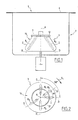
- FIGS 1 and 2 schematically illustrate a centrifuge 1 which comprises a tank 2, a rotor 3 disposed in the tank 2, and means 4 for rotating the rotor 3 around an axis of rotation A substantially vertical.
- the tank 2 comprises a movable access door 6 and means for refrigerating its interior atmosphere, which means are not shown in the figures.
- the rotor 3 is a generally frustoconical rotor with a central axis A. It is equipped with a removable closure cover 7. Cover 7 has not been shown in figure 2.
- the rotor 3 is for example made of metal and four housings offset from the axis A are formed there, namely a first pair of housings 8 1 and 8 2 and a second pair of housings 10 1 and 10 2 . It will be noted that the housings 10 1 and 10 2 are not shown in FIG. 1.
- the housings 8 1 and 8 2 of the first pair are symmetrical to each other with respect to the axis A.
- the housings 10 1 and 10 2 of the second pair are symmetrical to each other with respect to to axis A.
- the housings 8 1 , 8 2 , 10 1 and 10 2 have a similar shape elongated along a respective longitudinal direction D.
- each direction D is inclined relative to the axis of rotation A and cuts it at a geometric point located above the rotor 3 and its cover 7 .
- the housings 8 1 , 8 2 , 10 1 and 10 2 open into the upper surface 12 of the rotor to allow, when the cover 7 is removed, to introduce into the housings containers containing the product or products to be centrifuged, for example tubes closed by caps.
- the distribution of the housings 8 1 , 8 2 , 10 1 and 10 2 around the axis of rotation A is irregular.
- the rotor 3 would be invariant by a geometric rotation of axis A and angle equal to 90 ° ( ⁇ / 2 rad).
- the geometric image I (in double-dashed dashed line) of the housing 8 1 by such a rotation in a first direction S 1 would be confused with the housing 10 1 , housing which directly follows the housing 8 1 in this direction S 1 .
- the housing 10 1 is not confused with this image I but is, in top view, angularly offset from this image I by a non-zero angle ⁇ centered on the axis A and negative with respect to the direction S 1 .
- the housing 10 1 is the image, by a geometric rotation of axis A and of angle ⁇ , of the image I.
- the longitudinal directions D of the housings 10 1 and of the image I form a top view of an angle ⁇ centered on the axis A and negative when considering the direction S 1 .
- the angle ⁇ is for example 4 ° and can be understood more generally between 2 ° and 10 °.
- the housing 10 2 is angularly offset, in plan view, from the image not shown of the housing 8 2 by the aforementioned rotation.
- the housings 8 1 , 8 2 , 10 1 and 102 are invariant by a geometric rotation of axis A and of angle equal to 180 ° ( ⁇ rad) but not by a rotation of axis A and of angle equal to 90 ° ( ⁇ / 2 rad) as in the state of the art.
- the reason for this reduction or elimination of noise pollution may be as follows.
- the zones Z ( Figure 1) of the outer lateral surface 14 of the rotor 3 located radially opposite the housings 8 1 , 8 2 , 10 1 and 10 2 deform, under the effect of the centrifugal force, radially outward more strongly than the areas of the outer lateral surface 14 located between the housings.
- the reliefs thus created on the surface 14 are, like the housings 8 1 , 8 2 , 10 1 and 10 2 , invariant by a geometric rotation of axis A and of angle equal to 180 ° ( ⁇ rad), and not by a geometric rotation of axis A and angle equal to 90 ° as in the state of the art.
- the frequencies and intensities of the acoustic waves created during the rotational drive of the rotor are modified and the noise pollution reduced, or even eliminated.
- the angle ⁇ can be positive with respect to the direction S 1 .
- the housing 10 1 is viewed from above laterally translated, with respect to the image I of the housing 8 1 , opposite the direction S 1 of a distance d not nothing.
- the longitudinal directions D of the housing 10 1 and of the image I of the housing 8 1 are substantially parallel and spaced laterally from one another.
- the distance d is for example 2mm and can more generally be between 1 and 5mm.
- the housing 10 1 can be, in top view, offset laterally from the image I of the housing 8 1 in the direction S 1 .
- the housing 10 1 can be, in top view, resulting from a geometric translation of the image I, the direction of this translation not necessarily being orthogonal to the direction D of the image I.
- the housing 10 1 can be deduced from the image I of the housing 8 1 by a geometric transformation in a radial plane containing the axis of rotation A and the longitudinal direction D of the image I.
- FIGS. 4 and 5 illustrate a third embodiment in which the longitudinal direction D of the housing 10 1 is angularly offset by a non-zero angle ⁇ relative to the longitudinal direction D of the image I in the above-mentioned plane P ( figure 4).
- This plane P also contains the direction D of the housing 10 1 and corresponds to the right half-plane of FIG. 5.
- the housing 10 1 is the image, by a geometric rotation of angle ⁇ in the plane P, of the image I.
- angle ⁇ can be positive or negative.
- This angle ⁇ a by example a value of 4 ° and can be more generally between 2 ° and 10 °.
- FIG. 6 illustrates another embodiment in which the housing 10 1 is obtained from image I by geometric translation of a substantially constant distance ⁇ not zero in the radial plane P.
- the directions D of the housing 10 1 and of image I are substantially parallel and spaced from each other.
- the aforementioned translation can be such that the housing 10 1 is closer or more distant from the outer lateral surface 14 than the image I.
- the angle ⁇ or the distance ⁇ are sufficiently small so that on the one hand the homogeneity of the centrifugation treatment undergone by products received in the housings 8 1 , 8 2 , 10 1 and 10 2 is satisfactory and on the other hand the unbalances are reduced.
- FIG. 7 illustrates yet another embodiment where the housing 10 1 is the image by a geometric transformation of the image I, this geometric transformation comprising a geometric rotation and a geometric translation in the plane of FIG. 7 which is orthogonal to the axis of rotation A.
- the rotation is a rotation of axis A and of angle ⁇ .
- the translation is a translation in the plane of Figure 7 of a non-zero distance d in a direction which is not orthogonal to the direction D of image I.
- the combination of rotation and translation within the geometric transformation allows the housing 10 1 to remain sufficiently close to image I to limit the differences between the centrifugation force undergone by a product contained in the housing 10 1 and the centrifugation force of a product received in the housing 8 1 .
- FIG. 8 illustrates another embodiment in which the housing 10 1 is obtained from image I by a geometric transformation comprising a geometric rotation and a geometric translation in the radial plane P which comprises the axis of rotation A and the longitudinal direction D of image I.
- the rotation is a non-zero angle ⁇ rotation and the translation a translation of a non-zero distance ⁇ in one direction orthogonal to axis A.
- the combination of a translation and a rotation makes it possible to increase the homogeneity of the centrifugation treatment undergone by products received in the housings 8 1 , 8 2 , 10 1 and 10 2 , to limit unbalances and to reduce aesthetic inconvenience.
- the geometric transformation between the image I and the housing 10 1 may comprise a translation and / or a rotation in a plane orthogonal to the axis of rotation A, and a translation and / or a rotation in a radial plane containing axis A.
- translations and rotations described previously can be applied, for example separately each to a respective pair of dwellings when the number of dwellings is even and strictly greater than 4.
- the housings are symmetrical in pairs with respect to the axis A.
- the rotor 3 when the rotor 3 is provided with an even number n of housings, the rotor 3 will be invariant by a geometric rotation of axis A and of 180 ° angle which limits imbalances. More generally, an invariance by a geometric rotation of axis A and an angle strictly greater than 360 ° / n will make it possible to limit the imbalances.
Landscapes
- Centrifugal Separators (AREA)
Priority Applications (1)
| Application Number | Priority Date | Filing Date | Title |
|---|---|---|---|
| DE60301735.5T DE60301735T3 (de) | 2002-01-09 | 2003-01-07 | Rotor mit Behälteraufnahmen für zu zentrifugierende Produkte und entsprechende Zentrifuge |
Applications Claiming Priority (2)
| Application Number | Priority Date | Filing Date | Title |
|---|---|---|---|
| FR0200219A FR2834479B1 (fr) | 2002-01-09 | 2002-01-09 | Rotor a disposition amelioree de logements de reception de produits a centrifuger et centrifugeuse correspondante |
| FR0200219 | 2002-01-09 |
Publications (3)
| Publication Number | Publication Date |
|---|---|
| EP1329263A1 true EP1329263A1 (de) | 2003-07-23 |
| EP1329263B1 EP1329263B1 (de) | 2005-10-05 |
| EP1329263B2 EP1329263B2 (de) | 2014-07-30 |
Family
ID=8871212
Family Applications (1)
| Application Number | Title | Priority Date | Filing Date |
|---|---|---|---|
| EP03290034.2A Expired - Lifetime EP1329263B2 (de) | 2002-01-09 | 2003-01-07 | Rotor mit Behälteraufnahmen für zu zentrifugierende Produkte und entsprechende Zentrifuge |
Country Status (4)
| Country | Link |
|---|---|
| US (1) | US6986731B2 (de) |
| EP (1) | EP1329263B2 (de) |
| DE (1) | DE60301735T3 (de) |
| FR (1) | FR2834479B1 (de) |
Families Citing this family (2)
| Publication number | Priority date | Publication date | Assignee | Title |
|---|---|---|---|---|
| DE102008032073B4 (de) * | 2008-07-08 | 2015-02-05 | Thermo Electron Led Gmbh | Ausschwingeinheit für eine Zentrifuge |
| CN104056731B (zh) * | 2014-06-10 | 2017-03-29 | 苏州培英实验设备有限公司 | 离心振荡混匀一体机 |
Citations (3)
| Publication number | Priority date | Publication date | Assignee | Title |
|---|---|---|---|---|
| US4553955A (en) * | 1984-06-01 | 1985-11-19 | Beckman Instruments, Inc. | Multi-angle adapter for fixed angle centrifuge rotor |
| US5605529A (en) * | 1996-01-17 | 1997-02-25 | Norfolk Scientific, Inc. | High efficiency centrifuge rotor |
| JPH09262503A (ja) * | 1996-03-29 | 1997-10-07 | Hitachi Koki Co Ltd | 遠心分離機用ロータ |
Family Cites Families (9)
| Publication number | Priority date | Publication date | Assignee | Title |
|---|---|---|---|---|
| US3339836A (en) * | 1965-02-02 | 1967-09-05 | Internat Equipment Company | Centrifuges |
| DE3341323C2 (de) * | 1983-11-15 | 1987-02-19 | Heraeus Separationstechnik GmbH, 3360 Osterode | Laboratoriumszentrifuge |
| US4820257A (en) * | 1988-05-10 | 1989-04-11 | Beckman Instruments, Inc. | Rotor noise suppression |
| JPH05138072A (ja) * | 1991-11-25 | 1993-06-01 | Hitachi Koki Co Ltd | 遠心分離機用ロータ |
| JP3456552B2 (ja) * | 1994-10-05 | 2003-10-14 | 株式会社久保田製作所 | 遠心分離機のアングルロータ |
| JPH1015436A (ja) * | 1996-07-09 | 1998-01-20 | Tomy Seiko:Kk | 遠心分離方法および遠心分離機 |
| JPH10328582A (ja) * | 1997-05-29 | 1998-12-15 | Tomy Seiko:Kk | 遠心分離機のロータ |
| JP4061672B2 (ja) † | 1997-07-23 | 2008-03-19 | 日立工機株式会社 | 遠心分離機用アングルロータ |
| JP3967849B2 (ja) * | 1998-07-01 | 2007-08-29 | 株式会社トミー精工 | 遠心分離機 |
-
2002
- 2002-01-09 FR FR0200219A patent/FR2834479B1/fr not_active Expired - Fee Related
-
2003
- 2003-01-07 EP EP03290034.2A patent/EP1329263B2/de not_active Expired - Lifetime
- 2003-01-07 DE DE60301735.5T patent/DE60301735T3/de not_active Expired - Lifetime
- 2003-01-09 US US10/338,710 patent/US6986731B2/en not_active Expired - Lifetime
Patent Citations (3)
| Publication number | Priority date | Publication date | Assignee | Title |
|---|---|---|---|---|
| US4553955A (en) * | 1984-06-01 | 1985-11-19 | Beckman Instruments, Inc. | Multi-angle adapter for fixed angle centrifuge rotor |
| US5605529A (en) * | 1996-01-17 | 1997-02-25 | Norfolk Scientific, Inc. | High efficiency centrifuge rotor |
| JPH09262503A (ja) * | 1996-03-29 | 1997-10-07 | Hitachi Koki Co Ltd | 遠心分離機用ロータ |
Non-Patent Citations (1)
| Title |
|---|
| PATENT ABSTRACTS OF JAPAN vol. 1998, no. 02 30 January 1998 (1998-01-30) * |
Also Published As
| Publication number | Publication date |
|---|---|
| US6986731B2 (en) | 2006-01-17 |
| FR2834479B1 (fr) | 2004-11-19 |
| EP1329263B2 (de) | 2014-07-30 |
| FR2834479A1 (fr) | 2003-07-11 |
| DE60301735T3 (de) | 2015-02-19 |
| DE60301735D1 (de) | 2005-11-10 |
| US20030158026A1 (en) | 2003-08-21 |
| EP1329263B1 (de) | 2005-10-05 |
| DE60301735T2 (de) | 2006-03-16 |
Similar Documents
| Publication | Publication Date | Title |
|---|---|---|
| EP0911080B1 (de) | Zentrifuge mit abnehmbarem Rotor und einer Einrichtung zur axialen Verriegelung des Rotors auf der Antriebswelle, sowie Rotor für eine solche Zentrifuge | |
| US10682616B2 (en) | Centrifuge with exchangeable rotors | |
| EP2815140B1 (de) | Wälzlagervorrichtung und entsprechende rotierende maschine | |
| JP6406033B2 (ja) | 遠心機及び遠心機用スイングロータ | |
| FR2526105A1 (fr) | Embrayage, notamment pour vehicule automobile, avec un assemblage ameliore du couvercle sur le plateau de reaction | |
| EP2313958B1 (de) | Interner rotor für eine elektrische drehmaschine mit t-förmigen magnetischen keilen | |
| EP2316156A2 (de) | Interner rotor mit einer mit rillen versehenen welle, der für eine elektrische drehmaschine bestimmt ist | |
| EP1329263B1 (de) | Rotor mit Behälteraufnahmen für zu zentrifugierende Produkte und entsprechende Zentrifuge | |
| FR2844877A1 (fr) | Procede pour l'equilibrage rotatif d'un rotor de turbocompresseur avec machine electrique rotative | |
| CN108116157A (zh) | 具有可移除轮辋凸缘的飞行器轮 | |
| FR2558527A1 (fr) | Systeme de decompression automatique pour le demarrage d'un moteur | |
| EP0014138B1 (de) | Vorrichtung zum Fixieren der Fahrzeugräder auf einer Auswuchtmaschine | |
| EP0685045A1 (de) | Torsionsdämfper, insbesondere für kraftfahrzeuge mit ringförmigem abgedichtetem gehäuse | |
| FR2783726A1 (fr) | Mecanisme de montage et de demontage destine a un rotor de centrifugeuse | |
| FR3087481A1 (fr) | Ensemble d’equilibrage modulaire pour turbomachine | |
| EP1201957B1 (de) | Radbaugruppe mit einer Scheibenbremse für Fahrzeuge | |
| JP2567557Y2 (ja) | 遠心分離機用試料容器の保護カバー | |
| EP1564435A1 (de) | Axiallager für ein Schwungrad | |
| CA3259731A1 (en) | Rotor de machine electrique tournante et ensemble ralentisseur electromagnetique et generatrice | |
| FR3064903B1 (fr) | Outil de travail rotatif pour le broyage d'aliments, et accessoire de preparation culinaire comportant un tel outil de travail rotatif | |
| JP3677840B2 (ja) | 遠心分離機用ロータ | |
| WO2009004129A2 (fr) | Outillage de fixation d'un arbre de transmission et banc d'équilibrage comportant un tel outillage | |
| EP3329138A1 (de) | Faltenbalg für antriebsgelenk und zugehörige getriebeanordnung | |
| FR3145878A1 (fr) | Moyens de maintien d’un bol de centrifugation pour centrifugeuse | |
| FR3067393B1 (fr) | Piece tournante ayant une interface de liaison mecanique munie d’un moyen de positionnement axial |
Legal Events
| Date | Code | Title | Description |
|---|---|---|---|
| PUAI | Public reference made under article 153(3) epc to a published international application that has entered the european phase |
Free format text: ORIGINAL CODE: 0009012 |
|
| 17P | Request for examination filed |
Effective date: 20030524 |
|
| AK | Designated contracting states |
Designated state(s): DE ES FR GB IT TR |
|
| AX | Request for extension of the european patent |
Extension state: AL LT LV MK RO |
|
| AKX | Designation fees paid |
Designated state(s): DE ES FR GB IT TR |
|
| GRAP | Despatch of communication of intention to grant a patent |
Free format text: ORIGINAL CODE: EPIDOSNIGR1 |
|
| GRAS | Grant fee paid |
Free format text: ORIGINAL CODE: EPIDOSNIGR3 |
|
| GRAA | (expected) grant |
Free format text: ORIGINAL CODE: 0009210 |
|
| AK | Designated contracting states |
Kind code of ref document: B1 Designated state(s): DE ES FR GB IT TR |
|
| PG25 | Lapsed in a contracting state [announced via postgrant information from national office to epo] |
Ref country code: IT Free format text: LAPSE BECAUSE OF FAILURE TO SUBMIT A TRANSLATION OF THE DESCRIPTION OR TO PAY THE FEE WITHIN THE PRESCRIBED TIME-LIMIT;WARNING: LAPSES OF ITALIAN PATENTS WITH EFFECTIVE DATE BEFORE 2007 MAY HAVE OCCURRED AT ANY TIME BEFORE 2007. THE CORRECT EFFECTIVE DATE MAY BE DIFFERENT FROM THE ONE RECORDED. Effective date: 20051005 |
|
| REG | Reference to a national code |
Ref country code: GB Ref legal event code: FG4D Free format text: NOT ENGLISH |
|
| REF | Corresponds to: |
Ref document number: 60301735 Country of ref document: DE Date of ref document: 20051110 Kind code of ref document: P |
|
| PG25 | Lapsed in a contracting state [announced via postgrant information from national office to epo] |
Ref country code: ES Free format text: LAPSE BECAUSE OF FAILURE TO SUBMIT A TRANSLATION OF THE DESCRIPTION OR TO PAY THE FEE WITHIN THE PRESCRIBED TIME-LIMIT Effective date: 20060116 |
|
| GBT | Gb: translation of ep patent filed (gb section 77(6)(a)/1977) |
Effective date: 20060116 |
|
| PLBI | Opposition filed |
Free format text: ORIGINAL CODE: 0009260 |
|
| 26 | Opposition filed |
Opponent name: SIGMA LABORZENTRIFUGEN GMBH Effective date: 20060201 |
|
| PLAX | Notice of opposition and request to file observation + time limit sent |
Free format text: ORIGINAL CODE: EPIDOSNOBS2 |
|
| PLBB | Reply of patent proprietor to notice(s) of opposition received |
Free format text: ORIGINAL CODE: EPIDOSNOBS3 |
|
| APBP | Date of receipt of notice of appeal recorded |
Free format text: ORIGINAL CODE: EPIDOSNNOA2O |
|
| APAH | Appeal reference modified |
Free format text: ORIGINAL CODE: EPIDOSCREFNO |
|
| APBQ | Date of receipt of statement of grounds of appeal recorded |
Free format text: ORIGINAL CODE: EPIDOSNNOA3O |
|
| PG25 | Lapsed in a contracting state [announced via postgrant information from national office to epo] |
Ref country code: TR Free format text: LAPSE BECAUSE OF FAILURE TO SUBMIT A TRANSLATION OF THE DESCRIPTION OR TO PAY THE FEE WITHIN THE PRESCRIBED TIME-LIMIT Effective date: 20051005 |
|
| PGFP | Annual fee paid to national office [announced via postgrant information from national office to epo] |
Ref country code: FR Payment date: 20100208 Year of fee payment: 8 |
|
| APBU | Appeal procedure closed |
Free format text: ORIGINAL CODE: EPIDOSNNOA9O |
|
| PGFP | Annual fee paid to national office [announced via postgrant information from national office to epo] |
Ref country code: GB Payment date: 20110105 Year of fee payment: 9 |
|
| REG | Reference to a national code |
Ref country code: FR Ref legal event code: ST Effective date: 20110930 |
|
| PG25 | Lapsed in a contracting state [announced via postgrant information from national office to epo] |
Ref country code: FR Free format text: LAPSE BECAUSE OF NON-PAYMENT OF DUE FEES Effective date: 20110131 |
|
| GBPC | Gb: european patent ceased through non-payment of renewal fee |
Effective date: 20120107 |
|
| PG25 | Lapsed in a contracting state [announced via postgrant information from national office to epo] |
Ref country code: GB Free format text: LAPSE BECAUSE OF NON-PAYMENT OF DUE FEES Effective date: 20120107 |
|
| PLAB | Opposition data, opponent's data or that of the opponent's representative modified |
Free format text: ORIGINAL CODE: 0009299OPPO |
|
| R26 | Opposition filed (corrected) |
Opponent name: SIGMA LABORZENTRIFUGEN GMBH Effective date: 20060201 |
|
| PUAH | Patent maintained in amended form |
Free format text: ORIGINAL CODE: 0009272 |
|
| STAA | Information on the status of an ep patent application or granted ep patent |
Free format text: STATUS: PATENT MAINTAINED AS AMENDED |
|
| 27A | Patent maintained in amended form |
Effective date: 20140730 |
|
| AK | Designated contracting states |
Kind code of ref document: B2 Designated state(s): DE ES FR GB IT TR |
|
| REG | Reference to a national code |
Ref country code: DE Ref legal event code: R102 Ref document number: 60301735 Country of ref document: DE |
|
| REG | Reference to a national code |
Ref country code: DE Ref legal event code: R102 Ref document number: 60301735 Country of ref document: DE Effective date: 20140730 |
|
| REG | Reference to a national code |
Ref country code: DE Ref legal event code: R135 Ref document number: 60301735 Country of ref document: DE |
|
| REG | Reference to a national code |
Ref country code: DE Ref legal event code: R073 Ref document number: 60301735 Country of ref document: DE |
|
| REG | Reference to a national code |
Ref country code: DE Ref legal event code: R074 Ref document number: 60301735 Country of ref document: DE |
|
| REG | Reference to a national code |
Ref country code: DE Ref legal event code: R135 Ref document number: 60301735 Country of ref document: DE Effective date: 20141031 |
|
| REG | Reference to a national code |
Ref country code: DE Ref legal event code: R074 Ref document number: 60301735 Country of ref document: DE Effective date: 20141218 |
|
| PGFP | Annual fee paid to national office [announced via postgrant information from national office to epo] |
Ref country code: DE Payment date: 20181228 Year of fee payment: 17 |
|
| REG | Reference to a national code |
Ref country code: DE Ref legal event code: R119 Ref document number: 60301735 Country of ref document: DE |
|
| PG25 | Lapsed in a contracting state [announced via postgrant information from national office to epo] |
Ref country code: DE Free format text: LAPSE BECAUSE OF NON-PAYMENT OF DUE FEES Effective date: 20200801 |