EP1329708A2 - Spectrophotometre - Google Patents
Spectrophotometre Download PDFInfo
- Publication number
- EP1329708A2 EP1329708A2 EP03250187A EP03250187A EP1329708A2 EP 1329708 A2 EP1329708 A2 EP 1329708A2 EP 03250187 A EP03250187 A EP 03250187A EP 03250187 A EP03250187 A EP 03250187A EP 1329708 A2 EP1329708 A2 EP 1329708A2
- Authority
- EP
- European Patent Office
- Prior art keywords
- sample
- color measurement
- port
- measurement instrument
- camera
- Prior art date
- Legal status (The legal status is an assumption and is not a legal conclusion. Google has not performed a legal analysis and makes no representation as to the accuracy of the status listed.)
- Withdrawn
Links
Images


Classifications
-
- G—PHYSICS
- G01—MEASURING; TESTING
- G01J—MEASUREMENT OF INTENSITY, VELOCITY, SPECTRAL CONTENT, POLARISATION, PHASE OR PULSE CHARACTERISTICS OF INFRARED, VISIBLE OR ULTRAVIOLET LIGHT; COLORIMETRY; RADIATION PYROMETRY
- G01J3/00—Spectrometry; Spectrophotometry; Monochromators; Measuring colours
- G01J3/46—Measurement of colour; Colour measuring devices, e.g. colorimeters
- G01J3/50—Measurement of colour; Colour measuring devices, e.g. colorimeters using electric radiation detectors
-
- G—PHYSICS
- G01—MEASURING; TESTING
- G01J—MEASUREMENT OF INTENSITY, VELOCITY, SPECTRAL CONTENT, POLARISATION, PHASE OR PULSE CHARACTERISTICS OF INFRARED, VISIBLE OR ULTRAVIOLET LIGHT; COLORIMETRY; RADIATION PYROMETRY
- G01J3/00—Spectrometry; Spectrophotometry; Monochromators; Measuring colours
- G01J3/02—Details
-
- G—PHYSICS
- G01—MEASURING; TESTING
- G01J—MEASUREMENT OF INTENSITY, VELOCITY, SPECTRAL CONTENT, POLARISATION, PHASE OR PULSE CHARACTERISTICS OF INFRARED, VISIBLE OR ULTRAVIOLET LIGHT; COLORIMETRY; RADIATION PYROMETRY
- G01J3/00—Spectrometry; Spectrophotometry; Monochromators; Measuring colours
- G01J3/02—Details
- G01J3/0205—Optical elements not provided otherwise, e.g. optical manifolds, diffusers, windows
- G01J3/0229—Optical elements not provided otherwise, e.g. optical manifolds, diffusers, windows using masks, aperture plates, spatial light modulators or spatial filters, e.g. reflective filters
-
- G—PHYSICS
- G01—MEASURING; TESTING
- G01J—MEASUREMENT OF INTENSITY, VELOCITY, SPECTRAL CONTENT, POLARISATION, PHASE OR PULSE CHARACTERISTICS OF INFRARED, VISIBLE OR ULTRAVIOLET LIGHT; COLORIMETRY; RADIATION PYROMETRY
- G01J3/00—Spectrometry; Spectrophotometry; Monochromators; Measuring colours
- G01J3/02—Details
- G01J3/0205—Optical elements not provided otherwise, e.g. optical manifolds, diffusers, windows
- G01J3/0251—Colorimeters making use of an integrating sphere
-
- G—PHYSICS
- G01—MEASURING; TESTING
- G01J—MEASUREMENT OF INTENSITY, VELOCITY, SPECTRAL CONTENT, POLARISATION, PHASE OR PULSE CHARACTERISTICS OF INFRARED, VISIBLE OR ULTRAVIOLET LIGHT; COLORIMETRY; RADIATION PYROMETRY
- G01J3/00—Spectrometry; Spectrophotometry; Monochromators; Measuring colours
- G01J3/02—Details
- G01J3/0267—Sample holders for colorimetry
-
- G—PHYSICS
- G01—MEASURING; TESTING
- G01J—MEASUREMENT OF INTENSITY, VELOCITY, SPECTRAL CONTENT, POLARISATION, PHASE OR PULSE CHARACTERISTICS OF INFRARED, VISIBLE OR ULTRAVIOLET LIGHT; COLORIMETRY; RADIATION PYROMETRY
- G01J3/00—Spectrometry; Spectrophotometry; Monochromators; Measuring colours
- G01J3/02—Details
- G01J3/0278—Control or determination of height or angle information for sensors or receivers
-
- G—PHYSICS
- G01—MEASURING; TESTING
- G01J—MEASUREMENT OF INTENSITY, VELOCITY, SPECTRAL CONTENT, POLARISATION, PHASE OR PULSE CHARACTERISTICS OF INFRARED, VISIBLE OR ULTRAVIOLET LIGHT; COLORIMETRY; RADIATION PYROMETRY
- G01J3/00—Spectrometry; Spectrophotometry; Monochromators; Measuring colours
- G01J3/02—Details
- G01J3/0289—Field-of-view determination; Aiming or pointing of a spectrometer; Adjusting alignment; Encoding angular position; Size of measurement area; Position tracking
-
- G—PHYSICS
- G01—MEASURING; TESTING
- G01J—MEASUREMENT OF INTENSITY, VELOCITY, SPECTRAL CONTENT, POLARISATION, PHASE OR PULSE CHARACTERISTICS OF INFRARED, VISIBLE OR ULTRAVIOLET LIGHT; COLORIMETRY; RADIATION PYROMETRY
- G01J3/00—Spectrometry; Spectrophotometry; Monochromators; Measuring colours
- G01J3/02—Details
- G01J3/0291—Housings; Spectrometer accessories; Spatial arrangement of elements, e.g. folded path arrangements
-
- G—PHYSICS
- G01—MEASURING; TESTING
- G01J—MEASUREMENT OF INTENSITY, VELOCITY, SPECTRAL CONTENT, POLARISATION, PHASE OR PULSE CHARACTERISTICS OF INFRARED, VISIBLE OR ULTRAVIOLET LIGHT; COLORIMETRY; RADIATION PYROMETRY
- G01J3/00—Spectrometry; Spectrophotometry; Monochromators; Measuring colours
- G01J3/02—Details
- G01J3/04—Slit arrangements slit adjustment
-
- G—PHYSICS
- G01—MEASURING; TESTING
- G01J—MEASUREMENT OF INTENSITY, VELOCITY, SPECTRAL CONTENT, POLARISATION, PHASE OR PULSE CHARACTERISTICS OF INFRARED, VISIBLE OR ULTRAVIOLET LIGHT; COLORIMETRY; RADIATION PYROMETRY
- G01J3/00—Spectrometry; Spectrophotometry; Monochromators; Measuring colours
- G01J3/46—Measurement of colour; Colour measuring devices, e.g. colorimeters
- G01J3/50—Measurement of colour; Colour measuring devices, e.g. colorimeters using electric radiation detectors
- G01J3/502—Measurement of colour; Colour measuring devices, e.g. colorimeters using electric radiation detectors using a dispersive element, e.g. grating, prism
-
- G—PHYSICS
- G01—MEASURING; TESTING
- G01N—INVESTIGATING OR ANALYSING MATERIALS BY DETERMINING THEIR CHEMICAL OR PHYSICAL PROPERTIES
- G01N21/00—Investigating or analysing materials by the use of optical means, i.e. using sub-millimetre waves, infrared, visible or ultraviolet light
- G01N21/17—Systems in which incident light is modified in accordance with the properties of the material investigated
- G01N21/25—Colour; Spectral properties, i.e. comparison of effect of material on the light at two or more different wavelengths or wavelength bands
- G01N21/251—Colorimeters; Construction thereof
-
- G—PHYSICS
- G01—MEASURING; TESTING
- G01J—MEASUREMENT OF INTENSITY, VELOCITY, SPECTRAL CONTENT, POLARISATION, PHASE OR PULSE CHARACTERISTICS OF INFRARED, VISIBLE OR ULTRAVIOLET LIGHT; COLORIMETRY; RADIATION PYROMETRY
- G01J3/00—Spectrometry; Spectrophotometry; Monochromators; Measuring colours
- G01J3/46—Measurement of colour; Colour measuring devices, e.g. colorimeters
- G01J3/50—Measurement of colour; Colour measuring devices, e.g. colorimeters using electric radiation detectors
- G01J3/501—Colorimeters using spectrally-selective light sources, e.g. LEDs
-
- G—PHYSICS
- G01—MEASURING; TESTING
- G01N—INVESTIGATING OR ANALYSING MATERIALS BY DETERMINING THEIR CHEMICAL OR PHYSICAL PROPERTIES
- G01N2201/00—Features of devices classified in G01N21/00
- G01N2201/06—Illumination; Optics
- G01N2201/065—Integrating spheres
Definitions
- the present invention relates to spectrophotometers, and more particularly to benchtop spectrophotometers and/or those with improved targeting.
- Spectrophotometers are instruments used to determine the color of a sample.
- a spectrophotometer typically includes a source of illumination to illuminate the sample, a color measurement engine for detecting light reflected from the sample, and signal processing circuitry connected to the light measurement engine to compute curves or numerical values indicative of the color of the sample.
- the general principles of construction and use of spectrophotometers are well known to those skilled in the color measurement art.
- spectrophotometer uses an integrating sphere in which the light illuminating the sample is integrated to provide diffuse, uniform illumination over an exposed measurement area of the sample. Examples of such spectrophotometers are illustrated in U.S. Patent 6,061,140 issued May 9, 2000, entitled “Spectrophotometer With Selectable Measurement Area”; and U.S. Patent 5,369,481, issued November 29, 1994, entitled “Portable Spectrophotometer.” Both disclosed spectrophotometers are “portable” or “hand-held” units, in which the instrument is placed against the sample.
- benchtop units provide ultra-high levels of precision in determining color.
- benchtop units are stationary, and the samples to be measured are placed in or on the units for analysis.
- a significant challenge with benchtop units is the accurate positioning of the sample within the sample port, so that the desired area of the sample is measured. Accurate positioning of the sample is critical to accurate measurement.
- Prior artisans have taken two approaches in providing visual evaluation of the position of a sample within the sample port of a spectrophotometer.
- One instrument includes an optical port aligned with the sample port. A user may look through the port to visually observe the position of the sample within the sample port. However, use of the optical port can be physically awkward as the operator positions her eye and head to look into the sphere interior.
- Another instrument includes a split integrating sphere that can be opened to permit direct observation of the sample within the sample port. This procedure is awkward and exposes the sphere interior to possible dirt, smudges, and physical damage.
- a video camera preferably is used to monitor the position of the sample within the sample port prior to color measurement.
- the system preferably includes an integrating sphere, a beam splitter, a video camera, and a color measurement system.
- the beam splitter preferably is aligned with the viewing port of the sphere so that light reflected from the sample is directed both to the video camera and to the color measurement system.
- the image acquired by the video camera can preferably be observed to evaluate position of the sample within the sample port. If the position is not as desired, the sample is manually repositioned and rechecked until it is as desired. After the sample position is confirmed as accurate, the color measurement is preferably taken.
- the present invention in preferred arrangements permits the visual, real-time confirmation of proper sample position with respect to a color measurement before the color measurement is taken.
- a benchtop spectrophotometer constructed in accordance with a preferred embodiment of the invention is illustrated in the drawings and generally designated 10.
- the major components of the spectrophotometer are schematically illustrated in Fig. 3 and include an integrating sphere 12, a reticule/aperture wheel 14, a beam splitter 16, a video camera 18, a sample spectrograph 20, and a reference spectrograph 21.
- the sphere includes a sample port 30 and a viewing port 32.
- the reticule/aperture wheel 14 and the beam splitter 16 are optically aligned with both the viewing port 32 and the sample port 30 so that light reflected from the sample passes through the beam splitter.
- the video camera 18 and the sample spectrograph 20 are optically aligned -- physically in the case of the camera and by way of the fiber optic cable 33 in the case of the sample spectrograph -- so that both the camera and the sample spectrograph receives the identical information.
- a sample S is placed adjacent the sample port 30; and the light reflected from the sample passes through the viewing port 32, the wheel 14, and the beam splitter 16 to be directed to both the camera 18 and the sample spectrograph 20.
- the image produced by the video camera 18 can be viewed to determine whether the sample S is properly positioned within the sample port 30.
- a reticule (to be described) on the wheel 14 assists in that determination. If the sample is not properly positioned, the sample is repositioned and reevaluated for proper position as many times as is necessary. When the sample is properly positioned, the color is determined using the sample spectrograph 20.
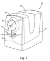
- the overall physical construction of the benchtop unit is illustrated in Figs. 1 and 2.
- the unit includes a chassis 40 which in turn includes a center casting 42, side castings 44 and 46, a support rib 48, and other components generally known to those skilled in the art.
- the individual components of the chassis 40 are interconnected to provide a rigid structural framework in which the remaining components are mounted in conventional fashion.
- the spectrophotometer (Figs. 1 and 2) further includes an enclosure base 50, a front casting 52, and an enclosure 54 to protectively enclose the unit 10 in an aesthetically pleasing fashion.
- the chassis and the enclosure pieces are intersecured in conventional fashion.
- the front casting 52 defines a plate receiver 60, and the sample port 30 is centered in the plate receiver.
- a finger access 76 facilitates removal of the sample aperture plates 64 from the plate receiver 60.
- any one of a plurality of plates 64 may be mounted in the plate receiver 60.
- Each plate defines a sample aperture 65 (see Fig. 3) of a unique size.
- three plates are provided and have sample aperture diameters of 5.5 mm, 11 mm, and 25 mm, respectively.
- the aperture 65 in each plate is concentric with, and therefore aligned with, the sample port 30.
- Each plate has the same outer diameter, so that each plate friction fits within the receiver 60.
- the sample holder 70 (Fig. 1) includes a spring-loaded, damped arm 72 and a support 74.
- the arm 72 biases the support into engagement with the plate 64.
- the support 74 may be pulled away from the plate 64 either to load a sample or to change the plate 64, for example, to one having a different diameter aperture.
- a transmissive sample area 80 permits a transmissive sample (e.g. a fluid) to be positioned between the sphere 12 and the optics 120 for measurement.
- a transmissive sample e.g. a fluid
- a cover also is included to cover the entire transmissive sample opening 80 during use to prevent ambient light from entering the unit during measurement of either a transmissive sample in the area 80 or a reflective sample in the sample holder 70.
- the integrating sphere 12 (Fig. 3) is generally known to those skilled in the art and most preferably is a six-inch Spectralon integrating sphere manufactured by Labsphere Inc. of North Sutton, New Hampshire.
- the sphere includes a sample port 30 and a viewing port 32.
- the sphere further includes an SCI/SCE port 80, a first illuminator 82, and a second illuminator assembly 84. Both of the ports 32 and 80 are oriented 8 degrees from normal to the sample aperture as is customary in d/8 spectrophotometers.
- the port 80 includes a removable reflective plug 86 operated by the stepper motor 88 as is conventional in the art.
- a specular included (SPIN) reading can be taken at port 32 when the plug 86 is in the port 80; and a specular excluded (SPEX) reading can be taken when the plug 86 is withdrawn from the port 80 creating a light trap.
- SPIN specular included
- SPEX specular excluded
- the first illuminator 82 provides illumination for the camera 18 during sample targeting.
- the illuminator may be a tungsten bulb, a light-emitting diode (LED), or virtually any other illuminator.
- the first illuminator 82 is actuated only during targeting as will be described.
- Baffle 112 is included within the sphere 12 to prevent the light from illuminator 82 from shining directly onto the viewing port 32.
- the second illuminator assembly 84 is generally well known to those skilled in the art and is operated only during a measurement.
- the assembly includes a pulse xenon lamp 100, a filter wheel 102, a UV filter wheel 104, and a diffuser 106.
- the filter wheel includes color balancing and ultraviolet (UV) filters.
- a stepper motor 108 operates the filter wheel 102. Accordingly, and under computer control, the filtering of the pulse xenon lamp can be controlled by operation of the stepper motor 108.
- Baffle 112 prevents the xenon light source from shining directly onto the sample port 30. And the baffle 90 prevents light from the illuminator assembly 84 from shining directly onto the viewing port 32.
- the construction and placement of the baffles 90 and 112 are known to those skilled in the art.
- the sample S can be mounted in alignment with the viewing port 30.
- the sample is mounted against the plate 64 (Figs. 1 and 3) and over the sample aperture 65.
- the beam splitter 16 is Product Number 03BSC 005 from Melles Griot.
- the camera is Product Number AS-02150-000 from Labsphere, Inc. with additional components (e.g. the OVT 511 CMOS camera chip) from OmniVision Technologies, Inc.
- the spectrographs are Product Number CP20 from Jobin Yvon Horiba. The arrangement, interrelationship, and use of these components is novel in the present invention.
- the light L reflected from the sample S and passing through the viewing port 32 also passes through the lens assembly 120 and the reticule/aperture wheel 14 before passing into the beam splitter 16.
- the beam splitter splits the sample light so that identical light information is directed to both the camera 18 and the sample spectrograph 20.
- the camera 18 is optically aligned with the viewing port 32 and the sample port 30 by way of a straight path, the beam splitter, and another straight path.
- the sample spectrograph 20 is optically aligned with the viewing port 32 and the sample port 30 by way of a straight path, the beam splitter, another straight path, and the fiber optic cable 33.
- the camera 18 could have a straight-line optical alignment with the ports, while the sample spectrograph is aligned with the 90 degree path of the beam splitter 16. Further alternatively, the camera and the sample spectrograph could have separate and independent optical alignments with the ports.
- the reference spectrograph 21 is optically connected to a reference port 35 in the sphere by way of the fiber optic cable 37 in conventional fashion for the acquisition of reference information indicative of the output of the illuminator assembly 84 during a color measurement.
- the optics module 130 is visible in Fig. 2 and is illustrated in detail in Figs. 4 and 5.
- the optics module includes the lens 120, wheel 14, beam splitter 16, and camera 18 schematically illustrated in Fig. 3. More specifically, the optics module includes a front housing 132, a rear housing 134, the beam splitter 16, a camera assembly 138 (comprising the camera 18), a wheel assembly 140 (including the wheel 14), and a fiber coupling 142.
- the front and rear housings 132 and 134 are configured to support the remaining components.
- the two housings are intersecured using shoulder screws 135.
- the transfer optics assembly 120 includes a pair of achromatic lenses 146 and 148 and a spacer 150.
- the transfer optics assembly 120 is supported by the front housing 132.
- the camera assembly includes a camera card 150 and a camera 18.
- the card 150 includes a USB connection 152 for plug-and-play connectability with standard operating systems such as Windows.
- the camera assembly 138 is mounted on the rear housing 134 using spacers 153 and screws 155.
- the reticule/aperture wheel assembly 160 (Figs. 4 and 5) includes the wheel 14, a motor adjust plate 162, and a stepper motor 164.
- a hub 166, an O-ring 168 and a sleeve 170 are used in mounting the wheel 14 on the stepper motor 164.
- the stepper motor is in turn mounted to the plate 162 using screws (not shown).
- the plate 162 is adjustably mounted in the recess 171 on the front housing 132 using the shoulder screws 172. Accordingly, the position of the filter wheel 14 with respect to the optical center of the transfer optics 120 can be precisely optically aligned with the other elements during assembly of the unit.
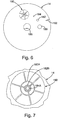
- the wheel 14 is illustrated in Fig. 6.
- the wheel defines three sample area apertures 180, 182 and 184 of varying diameters.
- the diameter of aperture 180 is 0.254 inch; the diameter of aperture 182 is 0.109 inch; and the diameter of aperture 184 is 0.056 inch.
- the wheel aperture sizes are selected in view of the sizes of the sample apertures 65 in the plates 64 so that each of the wheel apertures serves as a field stop for one of the sample apertures. Accordingly, the wheel apertures restrict the target sample area visible to both the camera 18 and the sample spectrograph 20.
- the disk aperture is sized so that the camera and spectrograph see a sample area slightly smaller than the sample aperture 65 so that the plate 64 is not inadvertently included in the image or in the color measurement.
- the wheel 14 also defines a central mounting aperture 186, which receives the hub 166 (see Figs. 4 and 5).
- the wheel 14 defines a reticule 190 illustrated in greater detail in Fig. 7.
- the reticule includes three rings 180a, 182a, and 184a having generally the same diameters as the wheel apertures 180, 182, and 184, respectively.
- the reticule 190 provides a targeting system for use (a) in aligning the sample within the sample aperture and (b) in evaluating whether the desired portion of the sample is within the selected sample target area.
- each of the apertures 180, 182, and 184 and the reticule 190 are on an imaginary circle concentric with the mounting aperture 186 of the wheel 14. Accordingly, any one of the apertures or reticule can be moved into alignment with the optical path by rotating the wheel 14 about its center.
- the stepper motor 164 (Figs. 4 and 5) provides this rotational movement under computer control.
- the slot 192 in the edge of the wheel 14 provides a mechanism for physically determining the position of the wheel 14 using the optical switch 196 (shown in Fig. 4).
- the reticule could be digitally or otherwise non-physically inserted into the video image.
- the fiber optic coupling 142 (Figs. 4 and 5) includes a focusing lens 200 and a cut-off filter 202. All of these elements are generally well-known to those skilled in the art.
- the present color measurement instrument enables the operator to confirm proper alignment of the sample S with respect to the sample aperture 30.
- GUI graphic user interface
- the GUI is in the controlling software in a computer (not shown) separate from the spectrophotometer 10.
- the computer and spectrophotometer interface with one another in any manner known to those skilled in the art.
- the operator also selects an appropriate plate 64 having the desired aperture; and the operator mounts the plate 64 in the plate receiver 60.
- the plate 64 friction-fits within the plate receiver. If a transmissive sample is to be measured, the operator mounts the plate having the largest aperture in the plate receiver; and the operator places the white calibration standard at the sample port.
- the sample is either a reflective sample (shown as S) or a transmissive sample (now shown).
- the sample is a reflective sample
- the sample is transmissive, the operator places the sample into the sample receiving area 80 and more specifically in a conventional sample holding mechanism (not shown). The remainder of this description assumes that a reflective sample is to be measured.
- the first illuminator 82 is powered continually except when measurements are taken to provide a light within the sphere 12.
- the light from the illuminator is diffused or integrated within the sphere.
- a portion of the light reflects off the sample S through the sample port 30 and the viewing port 32.
- the reflected light continues through the transfer optics 120 and the reticule wheel 14 to the beam splitter 16. From there, a portion of the light is directed to the camera 18.
- the default position of the wheel 14 aligns the reticule with the optical path. Consequently, both the sample S and the reticule 190 are imaged together by the video camera 18.
- the video image may be displayed on a monitor (not shown) to the operator. In the disclosed embodiment, the image is displayed on the same monitor on which the GUI is displayed.
- the operator evaluates the position of the sample with respect to the reticule and determines whether the area of interest is properly within the reticule ring 180a, 182a, or 184a corresponding to the selected sample area size. The operator decides whether repositioning the sample is necessary or desirable. The sample is repositioned as necessary or desired until the sample is properly aligned with respect to the reticule 190.
- the operator After the sample is properly positioned, the operator indicates through the GUI that a the sample is ready for a color measurement. That indication initiates several steps under computer control.
- the illuminator 82 is extinguished, and a settling period is initiated during which all light within the sphere is allowed to exit the sphere.
- the wheel 14 is rotated to align the desired aperture 180, 182, or 184 between the viewing port 32 and the beam splitter 16; and a settling period is initiated during which the wheel settles.
- the two settling periods may be the same period.
- the second illuminator 100 is actuated and readings are taken by both the sample spectrograph 20 and the reference spectrograph 21.
- the computer control also operates the plug 86 so that SPIN and/or SPEX readings are taken as selected by the operator using the GUI.
- the unit calculates color information of the sample in accordance with well known techniques.
- the color information is then displayed to the operator on the GUI and/or is stored in memory, again in accordance with techniques well-known to those skilled in the art.
- the present invention provides a system and method for enabling the accurate alignment of the sample for color measurement.
- the real-time visual confirmation of the sample's location eliminates the guesswork of sample positioning and ensures that the desired portion of the sample is appropriately read.
- the color measurement instrument of the present invention has been disclosed in conjunction with an integrating sphere and spectrographs, the invention is applicable to virtually any color measurement instrument using any color measurement technology. Further, while the invention has been described in conjunction with a benchtop instrument, the invention is applicable to portable instruments -- and indeed any color measurement instrument.
Landscapes
- Physics & Mathematics (AREA)
- Spectroscopy & Molecular Physics (AREA)
- General Physics & Mathematics (AREA)
- Health & Medical Sciences (AREA)
- Life Sciences & Earth Sciences (AREA)
- Chemical & Material Sciences (AREA)
- Analytical Chemistry (AREA)
- Biochemistry (AREA)
- General Health & Medical Sciences (AREA)
- Immunology (AREA)
- Pathology (AREA)
- Spectrometry And Color Measurement (AREA)
- Investigating Or Analysing Materials By Optical Means (AREA)
Applications Claiming Priority (2)
| Application Number | Priority Date | Filing Date | Title |
|---|---|---|---|
| US44529 | 1993-04-08 | ||
| US10/044,529 US6583879B1 (en) | 2002-01-11 | 2002-01-11 | Benchtop spectrophotometer with improved targeting |
Publications (2)
| Publication Number | Publication Date |
|---|---|
| EP1329708A2 true EP1329708A2 (fr) | 2003-07-23 |
| EP1329708A3 EP1329708A3 (fr) | 2003-07-30 |
Family
ID=21932894
Family Applications (1)
| Application Number | Title | Priority Date | Filing Date |
|---|---|---|---|
| EP03250187A Withdrawn EP1329708A3 (fr) | 2002-01-11 | 2003-01-13 | Spectrophotometre |
Country Status (3)
| Country | Link |
|---|---|
| US (1) | US6583879B1 (fr) |
| EP (1) | EP1329708A3 (fr) |
| JP (1) | JP2003232683A (fr) |
Cited By (2)
| Publication number | Priority date | Publication date | Assignee | Title |
|---|---|---|---|---|
| WO2018152360A1 (fr) | 2017-02-15 | 2018-08-23 | MarqMetrix Inc. | Dispositif de spectrométrie raman à banc de travail enfermé |
| WO2022027735A1 (fr) * | 2020-08-07 | 2022-02-10 | 深圳市华星光电半导体显示技术有限公司 | Dispositif de test et procédé de test pour la réflectivité d'un panneau à cristaux liquides |
Families Citing this family (45)
| Publication number | Priority date | Publication date | Assignee | Title |
|---|---|---|---|---|
| US6804006B2 (en) * | 2002-07-02 | 2004-10-12 | E. I. Du Pont De Nemours And Company | Color sample holder to enhance repeatability of instrumental color readings |
| US7280196B2 (en) * | 2003-02-24 | 2007-10-09 | Gretagmacbeth Llc | Spectrophotometer and subassemblies thereof |
| US8441700B2 (en) | 2003-04-25 | 2013-05-14 | Quad/Tech, Inc. | Image processing of a portion of multiple patches of a colorbar |
| US7627141B2 (en) | 2003-04-25 | 2009-12-01 | Quad/Tech, Inc. | System and method for measuring color on a printing press |
| US20040213436A1 (en) * | 2003-04-25 | 2004-10-28 | Quad/Tech, Inc. | System and method for measuring color on a printing press |
| US7248350B2 (en) * | 2004-04-27 | 2007-07-24 | E. I. Du Pont De Nemours And Company | Non-destructive method of determining the refractive index of clear coats |
| WO2005106415A1 (fr) * | 2004-04-30 | 2005-11-10 | X-Rite, Incorporated | Moteur colorimetrique a detecteurs paralleles |
| JP4506311B2 (ja) * | 2004-07-06 | 2010-07-21 | 凸版印刷株式会社 | 液体測色装置 |
| CN101076833A (zh) * | 2004-12-14 | 2007-11-21 | 阿克佐诺贝尔国际涂料股份有限公司 | 用于测量涂膜的粗糙度的方法和装置 |
| CA3138078C (fr) | 2007-10-02 | 2024-02-13 | Labrador Diagnostics Llc | Dispositifs modulaires a utiliser sur place et leurs utilisations |
| US7894064B2 (en) * | 2008-01-10 | 2011-02-22 | Hewlett-Packard Development Company, L.P. | Optical device for dispersing light |
| DE102009040642B3 (de) * | 2009-09-09 | 2011-03-10 | Von Ardenne Anlagentechnik Gmbh | Verfahren und Vorrichtung zur Messung von optischen Kenngrößen transparenter, streuender Messobjekte |
| US8854734B2 (en) * | 2009-11-12 | 2014-10-07 | Vela Technologies, Inc. | Integrating optical system and methods |
| CN101813455A (zh) * | 2010-04-13 | 2010-08-25 | 中国科学院长春光学精密机械与物理研究所 | 可调对比度目标源 |
| US8426800B2 (en) | 2010-09-09 | 2013-04-23 | Vela Technologies, Inc. | Integrating optical systems and methods |
| DE102010041749A1 (de) * | 2010-09-30 | 2012-04-05 | Carl Zeiss Microlmaging Gmbh | Messeinrichtungen und Vorrichtungen zur spektroskopischen Untersuchung von Proben |
| MX349288B (es) | 2011-01-21 | 2017-07-21 | Theranos Inc | Sistemas y metodos para maximizacion de uso de muestras. |
| EP2720015A4 (fr) | 2011-06-07 | 2015-03-18 | Prosper Creative Co Ltd | Dispositif et système de mesure, procédé d'alignement de position de mesure faisant appel à ces derniers et programme d'alignement de position de mesure |
| US9632102B2 (en) | 2011-09-25 | 2017-04-25 | Theranos, Inc. | Systems and methods for multi-purpose analysis |
| US20140170735A1 (en) | 2011-09-25 | 2014-06-19 | Elizabeth A. Holmes | Systems and methods for multi-analysis |
| US9664702B2 (en) | 2011-09-25 | 2017-05-30 | Theranos, Inc. | Fluid handling apparatus and configurations |
| US8475739B2 (en) | 2011-09-25 | 2013-07-02 | Theranos, Inc. | Systems and methods for fluid handling |
| US10012664B2 (en) | 2011-09-25 | 2018-07-03 | Theranos Ip Company, Llc | Systems and methods for fluid and component handling |
| US9810704B2 (en) | 2013-02-18 | 2017-11-07 | Theranos, Inc. | Systems and methods for multi-analysis |
| US8953160B2 (en) | 2012-05-14 | 2015-02-10 | Redox Biomedical, Inc. | Systems having a reflected light sensor and methods of use |
| EP2722664A1 (fr) * | 2012-10-19 | 2014-04-23 | Sika Technology AG | Procédé et agencement destinés à déterminer de façon quantitative des manques d'homogénéité dans une couche de fluide |
| US9076363B2 (en) * | 2013-01-07 | 2015-07-07 | Apple Inc. | Parallel sensing configuration covers spectrum and colorimetric quantities with spatial resolution |
| US20160054343A1 (en) * | 2013-02-18 | 2016-02-25 | Theranos, Inc. | Systems and methods for multi-analysis |
| JP6185864B2 (ja) * | 2013-06-07 | 2017-08-23 | 本田技研工業株式会社 | 積分球 |
| WO2015010714A1 (fr) * | 2013-07-22 | 2015-01-29 | Applied Materials, Inc. | Appareil et procédé de traitement de substrat de grande surface |
| US10422806B1 (en) | 2013-07-25 | 2019-09-24 | Theranos Ip Company, Llc | Methods for improving assays of biological samples |
| CN103557942B (zh) * | 2013-10-12 | 2014-09-17 | 杭州彩谱科技有限公司 | 双光源兼容sci/sce测试条件的测色仪及实现方法 |
| CN104749158B (zh) | 2013-12-27 | 2020-12-11 | 同方威视技术股份有限公司 | 珠宝玉石鉴定方法及装置 |
| US20150316411A1 (en) * | 2014-05-02 | 2015-11-05 | Kla-Tencor Corporation | Method and System for Intrinsic LED Heating for Measurement |
| WO2017135956A1 (fr) * | 2016-02-04 | 2017-08-10 | Datacolor Holding Ag | Procédé et appareil de mesure de couleur de couleurs non solides |
| US9784614B2 (en) * | 2015-02-09 | 2017-10-10 | Datacolor Holding Ag | Method and apparatus for color measurement of non-solid colors |
| USD796979S1 (en) * | 2015-09-02 | 2017-09-12 | Mettler-Toledo Gmbh | Spectrophotometer |
| US10408675B2 (en) | 2017-02-15 | 2019-09-10 | Marqmetrix, Inc. | Enclosed benchtop Raman spectrometry device |
| CN120668258A (zh) * | 2017-06-01 | 2025-09-19 | 柯尼卡美能达株式会社 | 分光光度计 |
| JP6656210B2 (ja) * | 2017-07-21 | 2020-03-04 | 株式会社日立ハイテクサイエンス | 分光蛍光光度計 |
| US11002676B2 (en) | 2018-04-09 | 2021-05-11 | Hunter Associates Laboratory, Inc. | UV-VIS spectroscopy instrument and methods for color appearance and difference measurement |
| DE102018120006A1 (de) * | 2018-08-16 | 2020-02-20 | Instrument Systems Optische Messtechnik Gmbh | Verfahren und Vorrichtung zur Überwachung eines Spektralradiometers |
| JP7409386B2 (ja) | 2019-09-12 | 2024-01-09 | コニカミノルタ株式会社 | 測色装置 |
| US12055641B2 (en) * | 2020-10-01 | 2024-08-06 | Woods Hole Oceanographic Institution | Methods and apparatus for direct calibration |
| JP2025112525A (ja) | 2024-01-19 | 2025-08-01 | コニカミノルタ株式会社 | 光学特性測定装置 |
Family Cites Families (24)
| Publication number | Priority date | Publication date | Assignee | Title |
|---|---|---|---|---|
| US3986778A (en) | 1975-10-01 | 1976-10-19 | International Business Machines Corporation | Spectrophotometer sample holder |
| US4101222A (en) | 1976-12-23 | 1978-07-18 | International Business Machines Corporation | Spectrophotometer sample holder with improved sample viewing apparatus |
| JPS6210668Y2 (fr) * | 1979-10-19 | 1987-03-13 | ||
| JPS56102451U (fr) * | 1980-01-09 | 1981-08-11 | ||
| JPS60244803A (ja) | 1984-05-21 | 1985-12-04 | Disco Abrasive Sys Ltd | 自動精密位置合せシステム |
| JPS6162825A (ja) * | 1984-09-05 | 1986-03-31 | Nippon Paint Co Ltd | 分光測色器による測色方法 |
| JPH0385429A (ja) * | 1989-08-30 | 1991-04-10 | Hitachi Ltd | 分光光度計 |
| US5369481A (en) | 1992-05-08 | 1994-11-29 | X-Rite, Incorporated | Portable spectrophotometer |
| JPH0650817A (ja) * | 1992-07-29 | 1994-02-25 | Minolta Camera Co Ltd | 試料の光学特性測定装置 |
| US5408294A (en) | 1993-05-28 | 1995-04-18 | Image Technology International, Inc. | 3D photographic printer with direct key-subject alignment |
| JP3346095B2 (ja) | 1995-05-17 | 2002-11-18 | ミノルタ株式会社 | 分光光度計 |
| JP3568631B2 (ja) * | 1995-05-29 | 2004-09-22 | オリンパス株式会社 | 宝石の色鑑定装置 |
| US5633676A (en) | 1995-08-22 | 1997-05-27 | E. L. Harley Inc. | Apparatus and method for mounting printing plates and proofing |
| JP3568687B2 (ja) * | 1995-12-06 | 2004-09-22 | オリンパス株式会社 | 照明装置及び色測定装置 |
| US5706083A (en) * | 1995-12-21 | 1998-01-06 | Shimadzu Corporation | Spectrophotometer and its application to a colorimeter |
| DE69631475T2 (de) | 1996-07-16 | 2005-01-13 | Perkin-Elmer Ltd., Beaconsfield | Kontrolle einer Mikroskopblende |
| JPH1098176A (ja) | 1996-09-19 | 1998-04-14 | Toshiba Corp | 固体撮像装置 |
| US6011648A (en) | 1997-05-15 | 2000-01-04 | Minolta Co., Ltd. | Optical system having an optical element made of resin |
| JPH11118603A (ja) | 1997-10-15 | 1999-04-30 | Minolta Co Ltd | 蛍光試料の分光特性測定装置及びその測定方法 |
| US6038024A (en) | 1998-01-09 | 2000-03-14 | Mht Optic Research | Method and an apparatus for determining the color stimulus specification of an object |
| US6008905A (en) | 1998-12-22 | 1999-12-28 | Deus Ex Machina Inc. | Method and apparatus for determining the appearance of an object |
| US6275295B1 (en) * | 1999-04-30 | 2001-08-14 | Midwest Research Institute | Optical system for determining physical characteristics of a solar cell |
| US6061140A (en) | 1999-05-27 | 2000-05-09 | X-Rite, Incorporated | Spectrophotometer with selectable measurement area |
| JP2002267600A (ja) * | 2001-03-12 | 2002-09-18 | Minolta Co Ltd | 反射特性測定装置 |
-
2002
- 2002-01-11 US US10/044,529 patent/US6583879B1/en not_active Expired - Lifetime
-
2003
- 2003-01-10 JP JP2003004881A patent/JP2003232683A/ja active Pending
- 2003-01-13 EP EP03250187A patent/EP1329708A3/fr not_active Withdrawn
Cited By (4)
| Publication number | Priority date | Publication date | Assignee | Title |
|---|---|---|---|---|
| WO2018152360A1 (fr) | 2017-02-15 | 2018-08-23 | MarqMetrix Inc. | Dispositif de spectrométrie raman à banc de travail enfermé |
| EP3583458A4 (fr) * | 2017-02-15 | 2021-06-23 | Marqmetrix Inc. | Dispositif de spectrométrie raman à banc de travail enfermé |
| WO2022027735A1 (fr) * | 2020-08-07 | 2022-02-10 | 深圳市华星光电半导体显示技术有限公司 | Dispositif de test et procédé de test pour la réflectivité d'un panneau à cristaux liquides |
| US11977285B2 (en) | 2020-08-07 | 2024-05-07 | Shenzhen China Star Optoelectronics Semiconductor Display Technology Co., Ltd. | Reflection rate detection device and reflection rate detection method for liquid crystal panel |
Also Published As
| Publication number | Publication date |
|---|---|
| US6583879B1 (en) | 2003-06-24 |
| EP1329708A3 (fr) | 2003-07-30 |
| JP2003232683A (ja) | 2003-08-22 |
Similar Documents
| Publication | Publication Date | Title |
|---|---|---|
| US6583879B1 (en) | Benchtop spectrophotometer with improved targeting | |
| US5754283A (en) | Color measuring device having interchangeable optical geometries | |
| US9325884B2 (en) | Cellscope apparatus and methods for imaging | |
| EP2529204B1 (fr) | Analyse de brillance de pierres précieuses | |
| RU2227287C2 (ru) | Способ и устройство для просмотра алмазов и драгоценных камней | |
| EP2062016B1 (fr) | Spectroscope à commande de la résolution spatiale | |
| US11392016B2 (en) | System and methods of fluorescence microscope calibration | |
| CN113260846B (zh) | 表面颜色和液体接触角成像 | |
| TW202426879A (zh) | 用於測定試樣的至少一個影像之成像品質的裝置和方法 | |
| GB1598659A (en) | Exposure determining devices for use in microphotography | |
| US20120268728A1 (en) | Gem positioning and analysis system | |
| EP1605292A1 (fr) | Microscope avec un dispositif pour déterminer le niveau d'éclairement | |
| EP1484600A3 (fr) | Sondes optiques et procédés d'analyse spectrale | |
| JPH08145888A (ja) | 蛍光測色装置 | |
| US7897912B2 (en) | Spectral and luminance measuring device employing array and single-channel detectors in combination | |
| EP3842772A1 (fr) | Mesure de la couleur d'un éclairage contrôlé d'une zone d'intérêt et n cibles de mesure de couleur | |
| EP0840106A2 (fr) | Spectrophotomètre pour transmission et réflexion avec des canaux de lumière à double usage | |
| US8164747B2 (en) | Apparatus, system and method for optical spectroscopic measurements | |
| CN212340438U (zh) | 一种双光路分光测色仪 | |
| KR20240156846A (ko) | 신속진단키트 리더기 | |
| JP4606814B2 (ja) | レンズメータ | |
| US9170153B2 (en) | Spectrometer for microscope illumination sources | |
| WO2023002464A1 (fr) | Procédé et appareil d'analyse de grain | |
| CN223986048U (zh) | 一种宝石鉴定仪 | |
| JP2797987B2 (ja) | 赤外顕微鏡 |
Legal Events
| Date | Code | Title | Description |
|---|---|---|---|
| PUAI | Public reference made under article 153(3) epc to a published international application that has entered the european phase |
Free format text: ORIGINAL CODE: 0009012 |
|
| PUAL | Search report despatched |
Free format text: ORIGINAL CODE: 0009013 |
|
| AK | Designated contracting states |
Designated state(s): AT BE BG CH CY CZ DE DK EE ES FI FR GB GR HU IE IT LI LU MC NL PT SE SI SK TR |
|
| AX | Request for extension of the european patent |
Extension state: AL LT LV MK RO |
|
| AK | Designated contracting states |
Designated state(s): AT BE BG CH CY CZ DE DK EE ES FI FR GB GR HU IE IT LI LU MC NL PT SE SI SK TR |
|
| AX | Request for extension of the european patent |
Extension state: AL LT LV MK RO |
|
| 17P | Request for examination filed |
Effective date: 20031015 |
|
| AKX | Designation fees paid |
Designated state(s): DE FR GB |
|
| 17Q | First examination report despatched |
Effective date: 20040527 |
|
| STAA | Information on the status of an ep patent application or granted ep patent |
Free format text: STATUS: THE APPLICATION IS DEEMED TO BE WITHDRAWN |
|
| 18D | Application deemed to be withdrawn |
Effective date: 20050719 |