EP1329782A2 - Montre munie d'un dispositif de suppression des irrégularités du mouvement des aiguilles - Google Patents
Montre munie d'un dispositif de suppression des irrégularités du mouvement des aiguilles Download PDFInfo
- Publication number
- EP1329782A2 EP1329782A2 EP03250192A EP03250192A EP1329782A2 EP 1329782 A2 EP1329782 A2 EP 1329782A2 EP 03250192 A EP03250192 A EP 03250192A EP 03250192 A EP03250192 A EP 03250192A EP 1329782 A2 EP1329782 A2 EP 1329782A2
- Authority
- EP
- European Patent Office
- Prior art keywords
- wheel
- chronograph
- hand motion
- spring
- timepiece
- Prior art date
- Legal status (The legal status is an assumption and is not a legal conclusion. Google has not performed a legal analysis and makes no representation as to the accuracy of the status listed.)
- Withdrawn
Links
Images


Classifications
-
- G—PHYSICS
- G04—HOROLOGY
- G04B—MECHANICALLY-DRIVEN CLOCKS OR WATCHES; MECHANICAL PARTS OF CLOCKS OR WATCHES IN GENERAL; TIME PIECES USING THE POSITION OF THE SUN, MOON OR STARS
- G04B35/00—Adjusting the gear train, e.g. the backlash of the arbors, depth of meshing of the gears
-
- G—PHYSICS
- G04—HOROLOGY
- G04F—TIME-INTERVAL MEASURING
- G04F7/00—Apparatus for measuring unknown time intervals by non-electric means
- G04F7/04—Apparatus for measuring unknown time intervals by non-electric means using a mechanical oscillator
- G04F7/08—Watches or clocks with stop devices, e.g. chronograph
- G04F7/0866—Special arrangements
Definitions
- the present invention relates to a hand motion irregularity suppressed timepiece having an indicating hand for showing a time or elapsed time such as a minute hand or second hand.
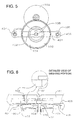
- Fig. 4 is a front view showing a conventional, hand motion irregularity suppressed timepiece, and shows an example of chronograph.
- Fig. 5 is a partial plan view of Fig. 4. Incidentally, Fig. 4 and Fig. 5 are views each showing a state after an assembly of parts such as a wheel has been completed.
- a second chronograph wheel 102 and a center wheel 104 are disposed between a train wheel bridge 101 and a bottom plate 106.
- a shaft 105 is integrally formed in the second chronograph wheel 102, the center wheel 104 is inserted through the shaft 105, and thus the second chronograph wheel 102 and the center wheel 104 are coaxially disposed.
- the second chronograph wheel 102 is meshed with a second chronograph intermediate wheel 103.
- a plate-like spring 401 for suppressing the hand motion irregularity of the second chronograph wheel 102 is disposed between the second chronograph wheel 102 and the center wheel 104.
- the spring 401 is formed in a long plate-like form, and in its center portion there is formed a through-hole 402 and in its both end portions there are formed through-holes 404, 406.
- the through-hole 402 is inserted through the shaft 105, and the through holes 404, 406 are so disposed that they are respectively fitted to convex portions 403, 405 formed in the bottom plate 106.
- the spring member 401 is constituted such that its center portion is deflected above (train wheel bridge 101 side) in Fig. 4 with respect to its both end portions and, after the assembly has been completed, functions such that the center portion of the spring 401 causes the second chronograph wheel 102 to pressure-contact with the train wheel bridge 101 as shown in Fig. 4. By this, the hand motion irregularity of the second chronograph wheel 102 is suppressed.
- Fig. 6 is a view showing an assembling process of the conventional timepiece mentioned above, and the same reference numeral is given to the same portion as Fig. 4 and Fig. 5.
- a subject of the present invention is to provide a hand motion irregularity suppressed timepiece whose assembling ability is improved.
- a hand motion irregularity suppressed timepiece characterized in that --in a timepiece adapted such that a 1st wheel and a 2nd wheel, which are coaxially disposed, and a 3rd wheel meshing with the 1st wheel are disposed between a 1st support member and a 2nd support member, and an indicating hand is rotated by rotation-driving each of the wheels-- there is provided a spring disposed between the 1st and 2nd wheels and having a flat portion and a bent portion formed in one end portion of the flat portion, and the 1st wheel is pressure-contacted with the 1st support member existing at a side opposite to the 2nd wheel by the fact that the flat portion of the spring is disposed between the 1st and 2nd wheels and the bent portion is sandwiched and supported under a pressurized state by the 1st and 2nd support members.
- the 1st wheel is pressure-contacted with the 1st support member existing at a side opposite to the 2nd wheel.
- the spring forms a gap between the 1st and 2nd wheels.
- the other end portion of the spring is provided with a through-hole through which a shaft for coaxially disposing the 1st and 2nd wheels is inserted.
- the shaft is constituted integrally with the 1st wheel, and the 2nd wheel is inserted through the shaft.
- the 1st wheel is a second chronograph wheel.
- the 2nd wheel is a number two wheel.
- the 3rd wheel is a second chronograph intermediate wheel.
- Fig. 1 is a partial front view of a hand motion irregularity suppressed timepiece according to an embodiment of the present invention, and shows an example of chronograph.
- Fig. 2 is a partial plan view of Fig. 1.
- Fig. 1 and Fig. 2 are views each showing a state after an assembly of parts such as a wheel has been completed.
- the second chronograph wheel 102 constituting a 1st wheel, the second chronograph intermediate wheel 103 constituting a 3rd wheel and the center wheel 104 constituting a 2nd wheel are disposed between the train wheel bridge 101 constituting a 1st support member and the bottom plate 106 constituting a 2nd support member.
- the shaft 105 is integrally formed in the second chronograph wheel 102.
- the center wheel 104 is inserted through the shaft 105, and thus the second chronograph wheel 102 and the center wheel 104 are coaxially disposed.
- a gear of the second chronograph wheel 102 is meshed with a pinion of the second chronograph intermediate wheel 103.
- a spring 107 for suppressing the hand motion irregularity of the second chronograph wheel 102 is disposed between the second chronograph wheel 102 and the center wheel 104.
- the spring 107 is an approximately long plate-like form as a whole and so constituted that its part is bent.
- the spring 107 has a flat portion 112 formed flatly and in a long plate-like form and a bent portion 111 provided in one end portion 110 and bent by a predetermined angle with respect to the flat portion 112 (hereafter, the spring 107 is referred to as cantilever spring).
- a through-hole 109 is provided in the other end portion 108 of the flat portion 112.
- the through-hole 109 is inserted through the shaft 105.
- the bent portion 111 is sandwiched and supported by the train wheel bridge 101 and the bottom plate 106 under a pressurized state, and the bent portion 111 is constituted so as to bias the other end portion 108 to the second chronograph wheel 102 side.
- the second chronograph wheel 102 is biased to the train wheel bridge 101 side by the spring 107 and held under a state of being pressure-contacted with the train wheel bridge 101, and a gap is formed between the second chronograph wheel 102 and the center wheel 104, so that the second chronograph wheel 102 and the center wheel 104 are held under a spaced state without contacting each other.
- the hand motion irregularity of the second chronograph wheel 102 is suppressed. Further, since the gap is formed between the second chronograph wheel 102 and the center wheel 104, it becomes possible to prevent the second chronograph wheel 102 from being rotated (so-called accompanying rotation) by a friction when the center wheel 104 is rotated.
- FIG. 3 is a view showing an assembling process of the hand motion irregularity suppressed timepiece according to the embodiment, and the same reference numeral is given to the same portion as Fig. 1 and Fig. 2.
- the second chronograph intermediate wheel 103 is mounted on the bottom plate 106, next the second chronograph wheel 102 is mounted on the spring 107, and thereafter the train wheel bridge 101 is mounted.
- the second chronograph wheel 102 is mounted on the flat portion 112 of the spring 107, it is unnecessary to push the spring 107 to the bottom plate 106 side in order to align the second chronograph wheel 102 and the second chronograph intermediate wheel 103 to thereby mesh them each other, and accordingly it becomes possible to easily align the second chronograph wheel 102 and the second chronograph intermediate wheel 103 to thereby mesh them each other.
- the bent portion 111 of the spring 107 is sandwiched and supported by the train wheel bridge 101 and the bottom plate 106 under the pressurized state, the other end portion 108 side of the spring 107 is biased to the train wheel bridge 101 side, so that the second chronograph wheel 102 is pressure-contacted with the train wheel bridge 101 by the spring 107 and thus the hand motion irregularity is suppressed.
- the second chronograph wheel 102 is pressure-contacted with the train wheel bridge 101 by the spring 107, the second chronograph wheel 102 becomes impossible to contact with the center wheel 104, so that the accompanying rotation between the second chronograph wheel 102 and the center wheel 104 is prevented.
- the hand motion irregularity suppressed timepiece is characterized in that --in a timepiece adapted such that the second chronograph wheel 102 and the center wheel 104, which are coaxially disposed, and the second chronograph intermediate wheel 103 meshing with the second chronograph wheel 102 are disposed between the train wheel bridge 101 and the bottom plate 106 and the indicating hand is rotated by rotation-driving each of the wheels 102 to 104-- there is provided the spring 107 disposed between the second chronograph wheel 102 and the center wheel 104 and having the flat portion 112 and the bent portion 111 formed in one end portion of the flat portion 112, and the second chronograph wheel 102 is pressure-contacted with the train wheel bridge 101 existing at a side opposite to the center wheel 104 by the fact that the flat portion 112 of the spring 107 is disposed between the second chronograph wheel 102 and the center wheel 104 and the bent portion 111 is sandwiched and supported under a pressurized state by the train wheel bridge 101 and the bottom plate 106
Landscapes
- Physics & Mathematics (AREA)
- General Physics & Mathematics (AREA)
- Measurement Of Unknown Time Intervals (AREA)
- Electromechanical Clocks (AREA)
- Measurement Of Distances Traversed On The Ground (AREA)
- Springs (AREA)
Applications Claiming Priority (2)
| Application Number | Priority Date | Filing Date | Title |
|---|---|---|---|
| JP2002009544A JP2003215267A (ja) | 2002-01-18 | 2002-01-18 | 運針むら抑制時計 |
| JP2002009544 | 2002-01-18 |
Publications (2)
| Publication Number | Publication Date |
|---|---|
| EP1329782A2 true EP1329782A2 (fr) | 2003-07-23 |
| EP1329782A3 EP1329782A3 (fr) | 2004-04-07 |
Family
ID=19191521
Family Applications (1)
| Application Number | Title | Priority Date | Filing Date |
|---|---|---|---|
| EP03250192A Withdrawn EP1329782A3 (fr) | 2002-01-18 | 2003-01-13 | Montre munie d'un dispositif de suppression des irrégularités du mouvement des aiguilles |
Country Status (5)
| Country | Link |
|---|---|
| US (1) | US6755567B2 (fr) |
| EP (1) | EP1329782A3 (fr) |
| JP (1) | JP2003215267A (fr) |
| CN (1) | CN1432882A (fr) |
| TW (1) | TW200302406A (fr) |
Families Citing this family (3)
| Publication number | Priority date | Publication date | Assignee | Title |
|---|---|---|---|---|
| US20050153263A1 (en) * | 2003-10-03 | 2005-07-14 | Scientific Learning Corporation | Method for developing cognitive skills in reading |
| JP6334217B2 (ja) * | 2014-03-14 | 2018-05-30 | セイコーインスツル株式会社 | 輪列機構、ムーブメント及び時計 |
| JP6583944B1 (ja) * | 2018-10-24 | 2019-10-02 | セイコーインスツル株式会社 | 時計用ムーブメントおよび時計 |
Family Cites Families (12)
| Publication number | Priority date | Publication date | Assignee | Title |
|---|---|---|---|---|
| CH218687A (de) * | 1941-06-13 | 1941-12-31 | Mido Ag | Sekundenzählvorrichtung an einer Uhr. |
| CH973868A4 (fr) * | 1968-06-28 | 1970-12-31 | ||
| DE1798352A1 (de) * | 1968-09-28 | 1971-08-12 | Kieninger & Obergfell | Wecker mit elektrischer Wecksignalgabe |
| GB1217647A (en) * | 1969-06-26 | 1970-12-31 | Eastern Time Ltd | Improvements relating to alarm clock and watches |
| US3609961A (en) * | 1970-02-16 | 1971-10-05 | Citizen Watch Co Ltd | Positioning mechanism for pressure spring means in timepieces |
| BE794271A (fr) * | 1972-01-21 | 1973-05-16 | Timex Corp | Mouvement d'horlogerie avec dispositif de reglage des aiguilles et d'arret du balancier |
| CH554016A (fr) * | 1972-03-15 | 1974-09-13 | ||
| US3864904A (en) * | 1973-05-08 | 1975-02-11 | Botho Jung | Watch with an adjustable time interval hand |
| JPS53128368A (en) * | 1977-04-15 | 1978-11-09 | Citizen Watch Co Ltd | Battery wrist watch with calendar |
| US4243329A (en) * | 1977-11-01 | 1981-01-06 | Citizen Watch Co., Ltd. | Watch movement construction |
| US5416752A (en) * | 1987-07-21 | 1995-05-16 | Seiko Epson Corporation | Timepiece |
| US5331608A (en) * | 1992-03-31 | 1994-07-19 | Citizen Watch Co., Ltd. | Electronic watch with an antenna for a receiving device |
-
2002
- 2002-01-18 JP JP2002009544A patent/JP2003215267A/ja active Pending
- 2002-12-31 TW TW091138085A patent/TW200302406A/zh unknown
-
2003
- 2003-01-09 US US10/339,071 patent/US6755567B2/en not_active Expired - Fee Related
- 2003-01-13 EP EP03250192A patent/EP1329782A3/fr not_active Withdrawn
- 2003-01-17 CN CN03100793A patent/CN1432882A/zh active Pending
Also Published As
| Publication number | Publication date |
|---|---|
| TW200302406A (en) | 2003-08-01 |
| CN1432882A (zh) | 2003-07-30 |
| US20030137902A1 (en) | 2003-07-24 |
| JP2003215267A (ja) | 2003-07-30 |
| EP1329782A3 (fr) | 2004-04-07 |
| US6755567B2 (en) | 2004-06-29 |
Similar Documents
| Publication | Publication Date | Title |
|---|---|---|
| EP1895650B1 (fr) | Actionneur piézoélectrique et dispositif électronique utilisant ledit actionneur | |
| US10078308B2 (en) | Timepiece wheel with play take-up | |
| US8641268B2 (en) | Platform escapement for a timepiece | |
| US20080008051A1 (en) | Mobile micromechanical element with shock controlled rotation | |
| JP6556914B2 (ja) | ケースミドル部とは独立なムーブメントを有するスケルトン腕時計 | |
| JP6114859B2 (ja) | 計時器又はクロノグラフ用のハート形カム | |
| US7258037B2 (en) | Gear protected against overloading | |
| EP1329782A2 (fr) | Montre munie d'un dispositif de suppression des irrégularités du mouvement des aiguilles | |
| EP3002636B1 (fr) | Roues coaxiales débrayables d'un mouvement horloger | |
| US12276942B2 (en) | Timepiece display mechanism | |
| JP4665516B2 (ja) | 遊星歯車機構およびその製造方法 | |
| US10054907B2 (en) | Timepiece movement including an analogue display | |
| JP6222725B2 (ja) | 時計用歯車、脱進機構、時計用ムーブメントおよび機械式時計 | |
| US9411311B2 (en) | Device for driving an analogue indicator, particularly a date ring | |
| JP4554970B2 (ja) | 時計ムーヴメント | |
| JP2000081114A (ja) | 歯車伝達機構 | |
| US11556092B2 (en) | Horological mobile component with element maintained by friction | |
| JP2995675B2 (ja) | アラーム付き電子時計 | |
| JP2540032Y2 (ja) | 携帯時計の受け部材固定構造 | |
| HK1057262A (en) | Timepiece with a device for suppressing hand motion irregularity | |
| JPH04102089U (ja) | 時計輪列の押エバネ構造 | |
| JP2017161305A (ja) | 機械部品、ムーブメントおよび時計 | |
| JPS6225755Y2 (fr) | ||
| HK1215077B (en) | Device for driving an analogue indicator, particularly a date ring | |
| JP2017223581A (ja) | 輪列機構、ムーブメントおよび時計 |
Legal Events
| Date | Code | Title | Description |
|---|---|---|---|
| PUAI | Public reference made under article 153(3) epc to a published international application that has entered the european phase |
Free format text: ORIGINAL CODE: 0009012 |
|
| AK | Designated contracting states |
Designated state(s): AT BE BG CH CY CZ DE DK EE ES FI FR GB GR HU IE IT LI LU MC NL PT SE SI SK TR |
|
| AX | Request for extension of the european patent |
Extension state: AL LT LV MK RO |
|
| PUAL | Search report despatched |
Free format text: ORIGINAL CODE: 0009013 |
|
| AK | Designated contracting states |
Kind code of ref document: A3 Designated state(s): AT BE BG CH CY CZ DE DK EE ES FI FR GB GR HU IE IT LI LU MC NL PT SE SI SK TR |
|
| AX | Request for extension of the european patent |
Extension state: AL LT LV MK RO |
|
| AKX | Designation fees paid | ||
| REG | Reference to a national code |
Ref country code: DE Ref legal event code: 8566 |
|
| STAA | Information on the status of an ep patent application or granted ep patent |
Free format text: STATUS: THE APPLICATION IS DEEMED TO BE WITHDRAWN |
|
| 18D | Application deemed to be withdrawn |
Effective date: 20041008 |