EP1329985A2 - Dispositif d antenne, appareil de communication et méthode de conception d' un tel dispositif d' antenne - Google Patents
Dispositif d antenne, appareil de communication et méthode de conception d' un tel dispositif d' antenne Download PDFInfo
- Publication number
- EP1329985A2 EP1329985A2 EP03000641A EP03000641A EP1329985A2 EP 1329985 A2 EP1329985 A2 EP 1329985A2 EP 03000641 A EP03000641 A EP 03000641A EP 03000641 A EP03000641 A EP 03000641A EP 1329985 A2 EP1329985 A2 EP 1329985A2
- Authority
- EP
- European Patent Office
- Prior art keywords
- antenna
- ground
- antenna apparatus
- present
- ground wire
- Prior art date
- Legal status (The legal status is an assumption and is not a legal conclusion. Google has not performed a legal analysis and makes no representation as to the accuracy of the status listed.)
- Withdrawn
Links
Images












Classifications
-
- H—ELECTRICITY
- H01—ELECTRIC ELEMENTS
- H01Q—ANTENNAS, i.e. RADIO AERIALS
- H01Q1/00—Details of, or arrangements associated with, antennas
- H01Q1/27—Adaptation for use in or on movable bodies
-
- H—ELECTRICITY
- H01—ELECTRIC ELEMENTS
- H01Q—ANTENNAS, i.e. RADIO AERIALS
- H01Q1/00—Details of, or arrangements associated with, antennas
- H01Q1/12—Supports; Mounting means
- H01Q1/22—Supports; Mounting means by structural association with other equipment or articles
- H01Q1/24—Supports; Mounting means by structural association with other equipment or articles with receiving set
- H01Q1/241—Supports; Mounting means by structural association with other equipment or articles with receiving set used in mobile communications, e.g. GSM
- H01Q1/242—Supports; Mounting means by structural association with other equipment or articles with receiving set used in mobile communications, e.g. GSM specially adapted for hand-held use
- H01Q1/243—Supports; Mounting means by structural association with other equipment or articles with receiving set used in mobile communications, e.g. GSM specially adapted for hand-held use with built-in antennas
-
- H—ELECTRICITY
- H01—ELECTRIC ELEMENTS
- H01Q—ANTENNAS, i.e. RADIO AERIALS
- H01Q1/00—Details of, or arrangements associated with, antennas
- H01Q1/08—Means for collapsing antennas or parts thereof
- H01Q1/084—Pivotable antennas
-
- H—ELECTRICITY
- H01—ELECTRIC ELEMENTS
- H01Q—ANTENNAS, i.e. RADIO AERIALS
- H01Q1/00—Details of, or arrangements associated with, antennas
- H01Q1/48—Earthing means; Earth screens; Counterpoises
-
- H—ELECTRICITY
- H01—ELECTRIC ELEMENTS
- H01Q—ANTENNAS, i.e. RADIO AERIALS
- H01Q9/00—Electrically-short antennas having dimensions not more than twice the operating wavelength and consisting of conductive active radiating elements
- H01Q9/04—Resonant antennas
- H01Q9/0407—Substantially flat resonant element parallel to ground plane, e.g. patch antenna
- H01Q9/0421—Substantially flat resonant element parallel to ground plane, e.g. patch antenna with a shorting wall or a shorting pin at one end of the element
Definitions
- the present invention relates to an antenna apparatus and a communication apparatus which are used in, for example, cellular phones as well as an antenna apparatus designing method.
- the conventional inverted F antenna comprises an antenna element 110 having a feeding plate 111 to which electricity is fed from a feeding point 112, a ground plate 120 arranged opposite the antenna element 110, and a short circuit plate 130 that electrically connects the antenna element 110 and the ground plate 120 together.
- the ground plate 120 has a generally rectangular shape in which long sides are each 165 mm in length (length), while short sides are each 44 mm in length (width) (see Figure 14).
- d 2 mm
- resonance frequency is 839 MHz and the frequency range within which VSWR ⁇ 2 is between 799 and 872 MHz and hence bandwidth is only 73 MHz.
- the specific band obtained by dividing the bandwidth by central frequency is only 8.7%.
- an object of the present invention to provide an antenna apparatus, a communication apparatus, and an antenna apparatus designing method that enable the thickness of folding cellular phones to be reduced, for example.
- the 1st aspect of the present invention is an antenna apparatus comprising:
- the 2nd aspect of the present invention is an antenna apparatus comprising:
- the 3rd aspect of the present invention is an antenna apparatus comprising:
- the 4th aspect of the present invention is the antenna apparatus according to the 1st aspect, wherein said ground wire (170) is at least partly located in a plane different from a plane in which said ground plate (120') is located.
- the 5th aspect of the present invention is the antenna apparatus according to the 4th aspect, wherein said antenna apparatus is used for cellular phone, and when said ground wire is located in a plane different from the plane in which said ground plate (120') is located, said ground wire is located further from a user's head when said user uses said cellular phone.
- the 6th aspect of the present invention is the antenna apparatus according to the 1st aspect, wherein said ground wire (140) is also used as a ground electrode.
- the 7th aspect of the present invention is the antenna apparatus according to the 6th aspect, wherein said antenna apparatus is used for a cellular phone having a camera (200) and/or a receiver, and said ground electrode is used in said camera (200) and/or said receiver.
- the 8th aspect of the present invention is the antenna apparatus according to the 1st aspect, wherein said ground wire (140) is constructed as a member different from said ground plate (120).
- the 9th aspect of the present invention is the antenna apparatus according to the 8th aspect, wherein said antenna apparatus is used in a cellular phone having an enclosure, and when said ground wire (140) is constructed as a member different from said ground plate (120), said ground wire (140) is constructed as a member stuck to an inner wall portion of said enclosure.
- the 10th aspect of the present invention is the antenna apparatus according to the 1st aspect, wherein at least part of said ground wire (140) is not opposite said antenna element (110).
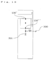
- the 11th aspect of the present invention is the antenna apparatus according to the 1st aspect, wherein said short circuit sections (130', 130") each have a plurality of short circuit pins (130', 130") corresponding to predetermined operating frequencies, respectively, and said antenna apparatus further comprises a switch circuit (300) used to carry out switching to one of said plurality of short circuit pins (130', 130") which is to be used.
- the 12th aspect of the present invention is the antenna apparatus according to the 1st aspect, wherein said antenna element (110) has a predetermined slit (S).
- the 13th aspect of the present invention is the antenna apparatus according to the 1st aspect, wherein said ground wire (140') partly has a coil (L1) and/or a capacitor (C1).
- the 14th aspect of the present invention is the antenna apparatus according to the 13th aspect, wherein said coil (L1) and/or said capacitor (C1) is used to equivalently adjust the electric length of said ground wire (140').
- the 15th aspect of the present invention is the antenna apparatus according to the 1st aspect, wherein a plurality of said ground wires (170, 180) are provided, and said ground wires (170, 180) correspond to respective predetermined operating frequencies.
- the 16th aspect of the present invention is the antenna apparatus according to the 4th aspect, wherein said ground wire (150') has a helical shape.
- the 17th aspect of the present invention is a communication apparatus comprising:
- the 18th aspect of the present invention is the communication apparatus according to the 17th aspect, wherein said antenna apparatus is used in a cellular phone, and said communication apparatus further comprises a first enclosure (2200) that houses said antenna apparatus, a second enclosure (2100) that is different from said first enclosure (2200), and a hinge section (2300) that joins said first enclosure (2200) and said second enclosure (2100) together.
- the 19th aspect of the present invention is a communication apparatus comprising:
- the 20th aspect of the present invention is the communication apparatus according to the 19th aspect, wherein said electric connection is such that one end of said hinge section (4300) is connected to a ground of said substrate (4220), with the other end open.
- the 21st aspect of the present invention is an antenna apparatus designing method for the antenna apparatus according to the 1st aspect, wherein said predetermined positions and/or said predetermined shapes are adjusted on the basis of predetermined rules.
- the 22nd aspect of the present invention is the antenna apparatus designing method according to the 21st aspect, wherein said ground wire (140') partly has a coil (L1) and/or a capacitor (C1), and said coil (L1) and/or said capacitor (C1) is used to equivalently adjust the electric length of said ground wire.
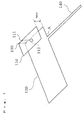
- the inverted F antenna of the present embodiment comprises an antenna element 110 having a feeding plate 111 to which electricity is fed from a feeding point 112, a ground plate 120 arranged opposite the antenna element 110, a short circuit plate 130 that electrically connects the antenna element 110 and the ground plate 120 together, and a ground wire 140 connected to the ground plate 120 at a predetermined position A and having a linear shape.
- the antenna element 110 corresponds to an antenna element of the present invention.
- the feeding plate 111 corresponds to a feeding section of the present invention.
- the ground plate 120 corresponds to a ground plate of the present invention.
- the short circuit plate 130 corresponds to a short circuit section of the present invention.
- the ground wire 140 corresponds to a ground wire of the present invention.
- the inverted F antenna of the present invention corresponds to an antenna apparatus of the present invention.
- the inverted F antenna of the present embodiment has a relatively small height (that is, the distance between the antenna element 110 and the ground plate 120) of 4 mm and can thus be incorporated adequately in a thin folding cellular phone.
- the ground plate 120 is composed of copper, conductive material, and has a generally rectangular shape in which long sides are each 165 mm in length (length), while short sides are each 44 mm in length (width). As described previously, the ground plate 120 has a length of 165 mm, a numerical value which substantially equals the overall length of a folding cellular phone as opened and which corresponds to ⁇ /2, i.e. half of a wavelength ⁇ in a 900-MHz band.
- the antenna element 110 is composed of copper, conductive material, and has a generally rectangular shape having a length of 40 mm and a width of 44 mm.
- the antenna element 110 is arranged over one of the short sides of the ground plate 120.
- the feeding plate 111 is composed of copper, conductive material, and has a planar shape having a width of 1 mm.
- the feeding plate 111 is electrically connected to the antenna element 110.
- the short circuit plate 130 is composed of copper, conductive material, and has a planar shape having a width of 3 mm.
- the short circuit plate 130 is electrically connected to the ground plate 120 and the antenna element 110.
- the distance between the feeding plate 111 and the short circuit plate 130 is 13 mm.
- the ground wire 140 is composed of copper, conductive material, and has a linear shape having a length of 90 mm and a width of 2 mm.
- the ground wire 140 is connected to the ground plate 120 at a predetermined position A, 38 mm away from that short side of the ground plate 120 which is located under the antenna element 110.
- the inverted F antenna of the present embodiment has a configuration similar to that of the previously described conventional inverted F antenna (see Figures 13 and 14) but is characterized by comprising the ground wire 140 connected to the ground plate 120 at the predetermined position A and having the linear shape.
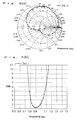
- the inverted F antenna of the present embodiment has a resonant frequency of 900 MHz and a corresponding VSWR of 1.28. Further, the frequency range within which VSWR ⁇ 2 is between 829 and 987 MHz. Consequently, the inverted F antenna of the present embodiment has a large bandwidth of 158 MHz and a specific band of 17.4%, which is double that in the prior art (as described previously, the specific band required for PDC communication is 17% or more) .
- the Smith chart for the inverted F antenna of the present embodiment contains inflection points (see Figure 3(a)). This means that there is double resonance between the antenna element 110 (see Figure 1) and the ground plate 120 (see Figure 1). That is, the ground wire 140 serves to fix the phase and amplitude of a particular portion of the ground plate 120, while changing the electric length of the ground plate 120. Accordingly, the resonant frequency of the antenna element 110 is close to the resonant frequency of the ground plate 120. This allows wide-band characteristics to be realized.
- the ground plate 120 is too large to resonate at a desired frequency. Accordingly, the ground wire 140 is used to equivalently reduce the electric length of the ground plate 120. However, the present invention is not limited to this aspect. If the ground plate is too small to resonate at a desired frequency, the ground wire 140 may be used to equivalently increase the electric length of the ground plate 120.
- the inverted F antenna of the present embodiment comprises the antenna element 110 having the feeding plate 111, the ground plate 120 arranged opposite the antenna element 110, the short circuit plate 130 that electrically connects the antenna element 110 and the ground plate 120 together, and a ground wire 150 connected to the ground plate 120 at a predetermined position B and having a generally spiral shape with a bent portion.
- the ground wire 150 corresponds to a ground wire of the present invention.
- the ground wire 150 is composed of copper, conductive material, and is connected to the ground plate 120 at a predetermined position B corresponding to a corner of the ground plate 120 located under the antenna element 110.
- the ground wire 150 has a generally spiral shape of linear width 2 mm which is as large as the width of the ground plate 120 on its short side, the generally spiral shape being formed outside that short side of the ground plate 120 which is located under the antenna element 110, so as not to lie opposite the antenna element 110.
- the inverted F antenna of the present embodiment has a configuration similar to that of the inverted F antenna of Embodiment 1, described previously (see Figures 1 and 2), but is characterized by comprising the ground wire 150 connected to the ground plate 120 at the predetermined position B and having the generally spiral shape with the bent portion.
- the ground wire 150 has a first to fifth bending points P1 to P5 each bent at a right angle. It is assumed that the bending points are sequentially numbered starting with the one closest to the tip of the ground wire 150 (accordingly, the fifth bending point P5 is close to the predetermined point B, corresponding to the root of the ground wire 150).
- the length between the tip of the ground wire 150 and the first bending point P1 is about 6 mm.
- the length between the first bending point P1 and the second bending point P2 is about 6 mm.
- the length between the second bending point P2 and the third bending point P3 is about 40 mm.
- the length between the third bending point P3 and the fourth bending point P4 is about 10 mm.
- the length between the fourth bending point P4 and the fifth bending point P5 is about 44 mm.
- the length between the fifth bending point P5 and the root of the ground wire 160 is about 20 mm.
- the portion between the tip of the ground wire 150 and the first bending point P1, the portion between the second bending point P2 and the third bending point P3, and the portion between the fourth bending point P4 and the fifth bending point P5 are substantially parallel with the short sides of the ground plate 120.
- the spacing between the portion between the tip of the ground wire 150 and the first bending point P1 and the portion between the second bending point P2 and the third bending point P3 is about 2 mm. Further, the spacing between the portion between the second bending point P2 and the third bending point P3 and the portion between the fourth bending point P4 and the fifth bending point P5 is about 2 mm.
- the portion between the first bending point P1 and the second bending point P2, the portion between the third bending point P3 and the fourth bending point P4, and the portion between the fifth bending point P5 and the root of the ground wire 160 are substantially parallel with the long sides of the ground plate 120.
- the spacing between the portion between the first bending point P1 and the second bending point P2 and the portion between the third bending point P3 and the fourth bending point P4 is about 36 mm. Further, the spacing between the portion between the third bending point P3 and the fourth bending point P4 and the portion between the fifth bending point P5 and the root of the ground wire 160 is about 40 mm.
- the frequency range within which VSWR ⁇ 2 is between 800 and 965 MHz. Consequently, the inverted F antenna of the present embodiment has a large bandwidth of 165 MHz and a specific band of 18.7%, which is larger than that in Embodiment 1, described previously.
- the shape of the ground wire 150 having the bent portion prevents the antenna from being massive and enables a small space to be effectively utilized. Furthermore, currents flow through the ground wire 150 in the opposite directions to balance a current in a distant field. Consequently, this embodiment is expected to produce an effect besides those described previously in Embodiment 1. That is, a radiation pattern is not disturbed.
- the ground plate 120 is too large to resonate at a desired frequency. Accordingly, the ground wire 150 is used to equivalently reduce the electric length of the ground plate 120.
- the present invention is not limited to this aspect. If the ground plate is too small to resonate at a desired frequency, the ground wire 150 may be used to equivalently increase the electric length of the ground plate 120.
- the inverted F antenna of the present embodiment comprises an antenna element 110' having a feeding pin 111', a ground plate 120' arranged opposite the antenna element 110', a short circuit pin 130' that electrically connects the antenna element 110' and the ground plate 120' together, and a ground wire 160 connected to the ground plate 120' at a predetermined position C and having a generally spiral shape with a bent portion.
- the antenna element 110' corresponds to an antenna element of the present invention.
- the feeding pin 111' corresponds to a feeding section of the present invention.
- the ground plate 120' corresponds to a ground plate of the present invention.
- the short circuit pin 130' corresponds to a short circuit section of the present invention.
- the ground wire 160 corresponds to a ground wire of the present invention.
- the inverted F antenna of the present embodiment thus has a configuration similar to that of the inverted F antenna of Embodiment 2, described previously (see Figures 4 and 5), but is characterized in that the ground wire 160 has a foot portion 161 extending along the long sides of the ground plate 120' and connected to the ground plate 120' at the predetermined position C, corresponding to the middle of one of the long sides of the ground plate 120', and has the generally spiral shape with the bent portion the width of which is as large as that of the ground plate 120' on its short side and which is formed outside that short sides of the ground plate 120' which is located under the antenna element 110'.
- the ground wire 160 has bending points P1 to P3 each bent at a right angle.
- a tip portion 162 corresponding to the portion between the tip of the ground wire 160 and the bending point P1 has a length D.
- the foot portion 161, i.e. the portion between the predetermined position C, corresponding to the root of the ground wire 160, and the corresponding short side of the ground plate 120' has a length L.
- the overall length of the ground wire 160 and the predetermined position C can be adjusted to make the resonant frequency of the ground plate 120' closer to that of the antenna element 110' (of course, the resonant frequency of the antenna element 110' may further be adjusted by forming a slit described later (see Figure 11)). That is, electromagnetic coupling of the ground plate 120' and the antenna element 110' is controlled to enable the parallel resonance therebetween to be generated.
- the length of the ground plate 120' is large and about ⁇ /2, i.e. half of a wavelength ⁇ in an operating frequency band (the case in which the antenna apparatus is incorporated in a folding cellular phone such as the one described above) or (2) conversely, it is small and less than ⁇ /4, then it is particularly effective to adjust the overall length of the ground wire 160 and the predetermined position C to equivalently increase or reduce the size of the ground plate 120'.
- ⁇ /2 i.e. half of a wavelength ⁇ in an operating frequency band (the case in which the antenna apparatus is incorporated in a folding cellular phone such as the one described above) or (2) conversely, it is small and less than ⁇ /4, then it is particularly effective to adjust the overall length of the ground wire 160 and the predetermined position C to equivalently increase or reduce the size of the ground plate 120'.
- this also applies to Embodiments 1 and 2, described previously.
- the inverted F antenna of the present embodiment comprises the antenna element 110' having the feeding pin 111', the ground plate 120' arranged opposite the antenna element 110', the short circuit pin 130' that electrically connects the antenna element 110' and the ground plate 120' together, and a ground wire 170 connected to the ground plate 120' at a predetermined position and having a bent shape.
- the ground wire 170 corresponds to a ground wire of the present invention.
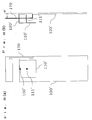
- the inverted F antenna of the present embodiment thus has a configuration similar to that of the inverted F antenna of Embodiment 3, described previously (see Figure 7), but is characterized in that the ground wire 170 is located in a plane different from the one in which the ground plate 120' is located (see Figure 8 (b)) (in Embodiments 1 to 3, described previously, the ground wire is located in the same plane in which the ground plate is located).
- a display is arranged opposite the antenna element 110' relative to the ground plate 120'.
- the location at which the display is arranged is close to a human body when the user talks over the cellular phone. Accordingly, a height H' (see Figure 8(b)) from the ground plate 120' is provided to reduce the adverse effects of the human body on the antenna element 110' (for example, the degradation of its characteristics attributed to a change in current distribution resulting from the abutment of the antenna element against the user's head or ear). This suppresses a decrease in antenna gain and an increase in SAR (Specific Absorption Rate).
- providing the height H' also reduces the adverse effects of the antenna element 110' on the human body (for example, the physiologically adverse effects of strong fields).
- the ground wire 170 is located in the plane parallel with the ground plate 120'.
- the ground wire 170 has only to be at least partly located in a plane different from the one in which the ground plate 120' is located. More specifically, the ground wire 170 may be located in a plane tilted so as not to be parallel with the ground plate 120'.
- the ground wire has only to be arranged so that an area in which electric fields from the ground wire are densely distributed (that is, an area in which the ground wire is electromagnetically coupled to the human body) lies away from the human body.
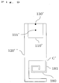
- the inverted F antenna of the present embodiment comprises the antenna element 110' having the feeding pin 111', a ground plate 120" arranged opposite the antenna element 110', the short circuit pin 130' that electrically connects the antenna element 110' and the ground plate 120" together, and a ground wire 180 connected to the ground plate 120" at a predetermined position C' and having a generally spiral shape with a bent portion.
- the ground wire 180 corresponds to a ground wire of the present invention.
- the inverted F antenna of the present embodiment thus has a configuration similar to that of the inverted F antenna of Embodiment 3, described previously (see Figure 7), but is characterized in that the ground wire 180 has a foot portion 181 extending along the long sides of the ground plate 120" and connected to the ground plate 120" at the predetermined position C', corresponding to the middle of one of the long sides of the ground plate 120", and has the generally spiral shape with the bent portion the width of which is equal to or smaller than that of the ground plate 120" on its short side and which is formed inside that short side of the ground plate 120" which is located under the antenna element 110' (in Embodiment 3, described previously, the ground wire 160 is formed outside that short side of the ground plate which is located under the antenna element 110').
- the inverted F antenna of the present embodiment is incorporated in a cellular phone, the outside of that short side of the ground plate which is located under the antenna element 110' lies close to the human body when the user talks over the cellular phone.
- the ground wire 180 is arranged inside the short side, and the length of the ground wire is adjusted (for example, in view of a change in current distribution caused by holding with the fingers) so that the peak point of a current flowing through the ground wire can be separated from the human body. This suppresses a decrease in antenna gain and an increase in SAR as in the case with Embodiment 4, described previously.
- Embodiments 1 to 5 have been described above in detail.
- the one ground wire is provided according to the present invention.
- the present invention is not limited to this aspect.
- two ground wires e.g. the ground wire 170 ( Figures 8 (a) and 8 (b)) and the ground wire 180 ( Figure 9) may be provided.
- one or more ground wires may be provided.
- the ground plate is resonated at resonant frequencies corresponding to the plurality of ground wires. Accordingly, this antenna apparatus can be implemented in a cellular phone compatible with a dual or triple band to actualize wide-band characteristics.
- the ground wire of the present invention is constructed as a member integrated with the ground plate.
- the ground wire of the present invention may be constructed as a member different from the ground plate, using a separate part.
- connectable connection terminals are provided at the predetermined position C (see Figure 7) of the ground plate 120' and the terminal position of the foot portion 161 (see Figure 7) of the ground wire 160. Then, the length of the ground wire and the position at which the ground wire is connected can be adjusted easily even if the ground plate 120' is composed of a metal chassis, an LCD holder, a substrate, or the like.
- the ground wire can be stuck to an inner wall portion of an enclosure of the cellular phone, or (2) it can be formed as a GND pattern on a flexible substrate. This increases the degree of freedom for design and reduces variations in characteristics associated with mass production.
- the ground wire of the present invention may also be used as a ground electrode (GND).
- GND ground electrode
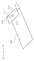
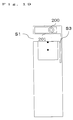
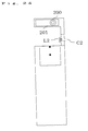
- the ground wire may also be used as a GND of a camera substrate 201 on which a camera 200 is mounted.
- the ground wire may also be used as a GND of a receiver or an audio speaker. Using the ground wire also as a ground electrode enables the number of parts required to be reduced.
- the ground wire can also be used as a ground electrode by using a structure provided with a horizontal slit S1 as shown in Figure 17, a structure provided with the horizontal slit S1 and a slit S2 formed in the ground wire as shown in Figure 18, or a structure provided with the horizontal slit S1 and a slit S3 formed in the ground plate as shown in Figure 19.
- Figure 17 is a plan view of an inverted F antenna in which the ground wire can also be used as a ground electrode by using the structure provided with the horizontal slit S1 according to the present invention.
- Figure 18 is a plan view of an inverted F antenna in which the ground wire can also be used as a ground electrode by using the structure provided with the horizontal slit S1 and the slit S2 formed in the ground wire according to the present invention.
- Figure 19 is a plan view of an inverted F antenna in which the ground wire can also be used as a ground electrode by using the structure provided with the horizontal slit S1 and the slit S3 formed in the ground plate according to the present invention.
- the ground wire of the present invention has the linear shape or the shape with the bent portion.
- the ground wire of the present invention may have a shape with one or more curves.
- Figure 20 (a) a plan view of an inverted F antenna in which a ground wire 190 according to the present invention has a shape with curves
- Figure 20(b) a plan view of an inverted F antenna in which a ground wire 190' according to the preset invention has a shape with curves
- the ground wires 190 and 190' in an antenna apparatus having a configuration similar to that of the antenna apparatus of Embodiment 1 may be curved.
- the ground wire of the present invention may have a helical or another shape which cannot be contained in any planes.
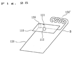
- a perspective view of an inverted F antenna in which a ground wire 150' according to the present invention has a helical shape the ground wire 150' in an antenna apparatus having a configuration similar to that of the antenna apparatus of Embodiment 2 may have a helical shape. This reduces the physical volume occupied by the ground wire to improve the degree of freedom for design.
- the ground wire of the present invention may partly have a coil and/or a capacitor.
- a plan view of an inverted F antenna in which a ground wire 140' according to the present invention partly has a coil L1 and a capacitor C1 the electric characteristics of the ground plate may be changed by partly forming the ground wire 140' as the coil L1 and the capacitor C1, the ground wire 140' being included in an antenna apparatus having a configuration similar to that of the antenna apparatus of Embodiment 1.
- the electric characteristics of the ground plate may be changed by partly forming the ground wire as the coil L2 and the capacitor C2, the ground wire being included in an antenna apparatus having a configuration similar to that of the antenna apparatus of the present embodiment (see Figure 17).
- This enables the electric length of the ground wire to be changed by changing the inductance of the coil or the capacitance of the capacitor. Consequently, these configurations improve the degree of freedom for design (Originally, the length of the groundwire is adjusted to adjust the electric length of the ground plate. However, even if the length of the ground wire deviates from its optimal dimension during mass production or for another reason, this deviation can be corrected using the coil or the capacitor) .
- ground wire of the present invention may be opposite the antenna element or may avoid being opposite the antenna element.
- at least part of the ground wire of the present invention may avoid being opposite the antenna element.
- the antenna element of the present invention may have a predetermined slit.
- a plan view of an inverted F antenna in which an antenna element according to the present invention has a predetermined slit S the slit S may be formed in the antenna element.
- the ground plate is resonated at resonant frequencies corresponding to the respective paths. This serves to actualize wide-band characteristics.
- the short circuit section of the present invention may have a plurality of short circuit pins corresponding to respective predetermined operating frequencies and a switch circuit used to carry out switching to one of the plurality of short circuit pins which is to be used.
- a short circuit pin 130" may be provided in addition to the short circuit pin 130' so as to switch the conductivity of a diode 301 in such a manner that an on-off switch circuit 300 is off while low frequency is used and is on while high frequency is used.
- this antenna apparatus can be implemented in a cellular phone compatible with a dual or triple band to actualize wide-band characteristics.
- the plurality of short circuit pins may be selected so as to ensure communication at more important frequencies.
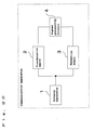
- the present invention includes a communication apparatus such as the one shown in Figure 22 showing a configuration of a communication apparatus of one embodiment of the present invention.
- This communication apparatus comprises an antenna apparatus 1 according to an embodiment of the present invention, transmission means 2 of transmitting electric wave signals using the antenna apparatus 1, a reception means 3 of receiving electric wave signals using the antenna apparatus 1, and a signal processing circuit 4 used to carry out signal processing so as to allow electric wave signals to be transmitted and received.
- the communication apparatus of this embodiment of the present invention is constructed, for example, as shown in Figure 23(a), a plan view of this communication apparatus and Figure 23(b), its side view.
- an antenna and liquid crystal module 1101 comprises a liquid crystal display 1110, a built-in antenna 1105 provided on the back surface of the liquid crystal display 1110 and utilizing the antenna apparatus of an embodiment of the present invention, a substrate 1106 provided on the bottom surface of the liquid crystal display 1110, and a driver circuit 1107 provided on the back surface of the substrate 1106.
- the liquid crystal display 1110 is composed of a display main body 1102, a metal reflecting plate 1103 provided on the back surface of an image display surface of the display main body 1102, and a frame 1104 which houses the display main body 1102 and the reflecting plate 1103 and which is composed of a U-shaped non-conductive member.
- the liquid crystal display 1110 is driven by a driver circuit 1107 to display an image on the image display surface of the display main body 1102.
- the end of an antenna element section 1105a on the rectangular plate is electrically connected to the reflecting plate 1103 via a metal connection section 1105c.
- the antenna element section 1105a is operated by electricity fed from a feeding point 1105b on the reflecting plate 1103 which is provided in a plane opposite to the display main body 1102 and the reflecting plate 1103. Inputs to and outputs from the feeding point 1105b are supplied by the transmission and reception means (not shown) on the substrate 1106.
- the antenna element section 1105a is provided directly on the back surface of the liquid crystal display 1110.
- the reflecting plate 1103 and the antenna element section 1105a are connected together via the connection section 1105c. Consequently, the reflecting plate 1103 functions as a ground plate for the antenna element section 1105a.
- a more specific example of the communication apparatus of the present invention is a folding cellular phone in which an inverted F antenna of any of the present embodiments described above is housed in an upper or lower enclosure.
- a specific example of a communication apparatus according to the present invention is a folding cellular phone such as the one shown in Figure 26, a side view of a folding cellular phone (1) as an embodiment of the communication apparatus of the present invention.
- This cellular phone comprises an upper enclosure 2100 that houses a display 2110; a lower enclosure 2200 that houses a key section 2210, a lower substrate 2220, and an inverted F antenna 2230 constructed similarly to the inverted F antenna of Embodiment 2, described above (see Figure 4), and having a ground wire 2231 (schematically illustrated); and a metal hinge section 2300 that joins the upper enclosure 2100 and the lower enclosure 2200 together.
- a communication apparatus is a folding cellular phone such as the one shown in Figure 27, a side view of a folding cellular phone (2) as an embodiment of the communication apparatus of the present invention.
- This cellular phone comprises an upper enclosure 3100 that houses a display 3110, an upper substrate 3120, and an inverted F antenna 3130 constructed similarly to the inverted F antenna of Embodiment 2, described above (see Figure 4), and having a ground wire 3131 (schematically illustrated); a lower enclosure 3200 that houses a key section 3210 and a lower substrate 3220; and a metal hinge section 3300 that joins the upper enclosure 3100 and the lower enclosure 3200 together.
- the lower enclosure 2200 corresponds to a first enclosure of the present invention.
- the upper enclosure 2100 corresponds to a second enclosure of the present invention.
- the metal hinge section 2300 corresponds to a hinge section of the present invention.
- the upper enclosure 3100 corresponds to a first enclosure of the present invention.
- the lower enclosure 3200 corresponds to a second enclosure of the present invention.
- the metal hinge section 3300 corresponds to a hinge section of the present invention.
- an inverted F antenna 4210 may be housed in a lower enclosure 4200, and an upper enclosure 4100 and the lower enclosure 4200 may be joined together via a metal hinge section 4300.
- a GND of a lower substrate 4220 housed in the lower enclosure 4200 and the metal hinge section 4300 may be electrically connected together via a connection element 4400 at at least one point (As shown in Figure 29, desirably, only one of the opposite ends of the metal hinge section 4300 is connected to the GND of the lower substrate 4220, with the other open.
- the inverted Fantenna 4210 corresponds to a predetermined antenna apparatus of the present invention.
- the lower substrate 4220 corresponds to a predetermined substrate of the present invention.
- the lower enclosure 4200 corresponds to a first enclosure of the present invention.
- the upper enclosure 4100 corresponds to a second enclosure of the present invention.
- the metal hinge section 4300 corresponds to a hinge section of the present invention. The above configuration allows the metal hinge section to function as a part of the ground wire.
- the inverted F antenna 4210 may be a conventional inverted F antenna without ground wires.
- the ground plate is to be resonated at a plurality of resonant frequencies
- the inverted F antenna of any of the present embodiments described above may be used.
- the connection element 4400 and the metal hinge section 4300 need not be directly connected together but may be connected via capacitance. In short, this connection has only to be accomplished as an electric one in a high-frequency region.
- the antenna apparatus of the present invention is the inverted F antenna.
- the antenna apparatus of the present invention may be of an unbalanced type.
- the inverted F antenna is desirably used in terms of a wider band and reduced size.
- a first aspect of the present invention provides, for example, an inverted F antenna with its thickness reduced.
- a second aspect of the present invention provides, for example, an inverted F antenna with its thickness further reduced.
- a third aspect of the present invention provides, for example, an inverted F antenna with its thickness further reduced.
- a fourth aspect of the present invention provides, for example, an inverted F antenna with a decrease in antenna gain and an increase in SAR suppressed.
- a fifth aspect of the present invention provides, for example, an inverted F antenna that serves to lower the adverse effects of a human body or the adverse effects on it when the user talks over a cellular phone, and with a decrease in antenna gain and an increase in SR suppressed.
- a sixth aspect of the present invention provides, for example, a cellular phone with the number of parts reduced.
- a seventh aspect of the present invention provides, for example, a cellular phone which allows a GND of a receiver or an audio speaker to be shared and which requires a reduced number of parts.
- An eighth aspect of the present invention provides, for example, an inverted F antenna which serves to improve the degree of freedom for design and which suppresses variations in characteristics associated with mass production.
- a ninth aspect of the present invention provides, for example, a cellular phone which serves to improve the degree of freedom for design and which suppresses variations in characteristics associated with mass production.
- a tenth aspect of the present invention provides, for example, an inverted F antenna with the degree of freedom for design improved.
- An eleventh aspect of the present invention provides, for example, a cellular phone which is compatible with a dual or triple band and which has wide-band characteristics.
- a twelfth aspect of the present invention provides, for example, an inverted F antenna with the degree of freedom for design improved.
- a thirteenth aspect of the present invention provides, for example, an inverted F antenna with the degree of freedom for design improved.
- a fourteenth aspect of the present invention provides, for example, an inverted F antenna with the degree of freedom for design further improved.
- a fifteenth aspect of the present invention provides, for example, a cellular phone which is compatible with a dual or triple band and which has wide-band characteristics.
- a sixteenth aspect of the present invention provides, for example, an inverted F antenna with a decrease in antenna gain and an increase in SAR suppressed.
- a seventeenth aspect of the present invention provides, for example, a cellular phone with its thickness reduced and having wide-band characteristics.
- An eighteenth aspect of the present invention provides, for example, a folding cellular phone with its thickness reduced and having wide-band characteristics.
- a nineteenth aspect of the present invention provides, for example, a thin folding cellular phone.
- a twentieth aspect of the present invention provides, for example, a thinner folding cellular phone.
- a twenty-first aspect of the present invention provides, for example, an inverted F antenna designing method with the degree of freedom for design improved.
- a twenty-second aspect of the present invention provides, for example, an inverted F antenna designing method with the degree of freedom for design further improved.
- the present invention has the advantage of implementing, for example, a folding cellular phone with its thickness reduced.
Landscapes
- Engineering & Computer Science (AREA)
- Computer Networks & Wireless Communication (AREA)
- Waveguide Aerials (AREA)
- Support Of Aerials (AREA)
- Details Of Aerials (AREA)
Applications Claiming Priority (2)
| Application Number | Priority Date | Filing Date | Title |
|---|---|---|---|
| JP2002010572 | 2002-01-18 | ||
| JP2002010572 | 2002-01-18 |
Publications (2)
| Publication Number | Publication Date |
|---|---|
| EP1329985A2 true EP1329985A2 (fr) | 2003-07-23 |
| EP1329985A3 EP1329985A3 (fr) | 2004-12-22 |
Family
ID=19191604
Family Applications (1)
| Application Number | Title | Priority Date | Filing Date |
|---|---|---|---|
| EP03000641A Withdrawn EP1329985A3 (fr) | 2002-01-18 | 2003-01-15 | Dispositif d antenne, appareil de communication et méthode de conception d' un tel dispositif d' antenne |
Country Status (4)
| Country | Link |
|---|---|
| US (1) | US7362271B2 (fr) |
| EP (1) | EP1329985A3 (fr) |
| KR (1) | KR20030063168A (fr) |
| CN (1) | CN1433104A (fr) |
Cited By (9)
| Publication number | Priority date | Publication date | Assignee | Title |
|---|---|---|---|---|
| EP1472758A2 (fr) * | 2002-02-06 | 2004-11-03 | Siemens Aktiengesellschaft | Appareil de radiocommunication et platine de circuits comportant au moins un element de correction conducteur |
| EP1755190A4 (fr) * | 2004-05-24 | 2008-05-14 | Matsushita Electric Industrial Co Ltd | Unité sans fil portable pliante |
| WO2009027763A1 (fr) | 2007-07-18 | 2009-03-05 | Nokia Corporation | Arrangement d'antenne |
| EP2110882A1 (fr) * | 2008-04-16 | 2009-10-21 | Apple Inc. | Antennes pour dispositifs électroniques sans fil |
| EP2040328A4 (fr) * | 2006-06-29 | 2010-04-21 | Mitsubishi Materials Corp | Dispositif d'antenne |
| US8319692B2 (en) | 2009-03-10 | 2012-11-27 | Apple Inc. | Cavity antenna for an electronic device |
| US9178268B2 (en) | 2012-07-03 | 2015-11-03 | Apple Inc. | Antennas integrated with speakers and methods for suppressing cavity modes |
| US9186828B2 (en) | 2012-06-06 | 2015-11-17 | Apple Inc. | Methods for forming elongated antennas with plastic support structures for electronic devices |
| WO2015194083A1 (fr) * | 2014-06-16 | 2015-12-23 | Sony Corporation | Dispositif antenne |
Families Citing this family (24)
| Publication number | Priority date | Publication date | Assignee | Title |
|---|---|---|---|---|
| JP2004104419A (ja) * | 2002-09-09 | 2004-04-02 | Hitachi Cable Ltd | 携帯無線機用アンテナ |
| JP4605590B2 (ja) * | 2004-11-26 | 2011-01-05 | 京セラ株式会社 | 無線端末装置 |
| US7843391B2 (en) * | 2006-09-15 | 2010-11-30 | Itron, Inc. | RF local area network antenna design |
| JP5078090B2 (ja) * | 2007-08-10 | 2012-11-21 | パナソニック株式会社 | アンテナ素子及び携帯無線機 |
| CN101779330A (zh) * | 2007-08-10 | 2010-07-14 | 松下电器产业株式会社 | 天线元件和便携式无线装置 |
| JP4655095B2 (ja) * | 2008-02-18 | 2011-03-23 | ミツミ電機株式会社 | アンテナ装置 |
| US8325955B2 (en) * | 2008-03-17 | 2012-12-04 | Auden Techno Corp. | Method for improving compatibility of hearing aid with antenna |
| US20100026580A1 (en) * | 2008-07-31 | 2010-02-04 | Auden Techno Corp. | PIFA antenna design method |
| US8656579B2 (en) * | 2008-08-29 | 2014-02-25 | Motorola Mobility Llc | Method of forming a housing with integral antenna |
| US7921553B2 (en) * | 2008-09-25 | 2011-04-12 | Motorola Mobility, Inc. | Method of making a customized wireless communication device |
| WO2010042853A1 (fr) * | 2008-10-09 | 2010-04-15 | Johnson Greg F | Système d'antenne ayant un résonateur antenne planaire en forme de f inversé compact dont une section est ouverte |
| US8421685B2 (en) * | 2009-05-07 | 2013-04-16 | Ethertronics, Inc. | Spatial filter for near field modification in a wireless communication device |
| EP2348578A1 (fr) * | 2010-01-20 | 2011-07-27 | Insight sip sas | Structure améliorée d'antenne dans un boîtier |
| US20110273338A1 (en) * | 2010-05-10 | 2011-11-10 | Pinyon Technologies, Inc. | Antenna having planar conducting elements and at least one space-saving feature |
| US8462070B2 (en) | 2010-05-10 | 2013-06-11 | Pinyon Technologies, Inc. | Antenna having planar conducting elements, one of which has a plurality of electromagnetic radiators and an open slot |
| US9886066B2 (en) * | 2010-07-02 | 2018-02-06 | BlackBerrry Limited | Mobile wireless communications device including a keyboard assembly for reducing SAR and related methods |
| US9088069B2 (en) * | 2011-09-21 | 2015-07-21 | Sony Corporation | Wireless communication apparatus |
| US9318793B2 (en) | 2012-05-02 | 2016-04-19 | Apple Inc. | Corner bracket slot antennas |
| CN104716416A (zh) * | 2013-12-13 | 2015-06-17 | 展讯通信(上海)有限公司 | 一种天线装置 |
| CN109494450B (zh) * | 2018-12-27 | 2024-04-12 | 深圳市道通智能航空技术股份有限公司 | 一种天线及无人飞行器 |
| CN109841944B (zh) * | 2019-03-26 | 2021-07-27 | 青岛海信移动通信技术股份有限公司 | 天线和终端 |
| CN115663474B (zh) * | 2022-10-31 | 2026-01-23 | 歌尔股份有限公司 | Uwb天线及电子设备 |
| KR102563934B1 (ko) * | 2023-01-26 | 2023-08-04 | 주식회사 오성전자 | Pifa 타입 안테나 |
| CN116111332A (zh) * | 2023-02-16 | 2023-05-12 | 江苏信维智能汽车互联科技有限公司 | 天线及天线制造方法 |
Family Cites Families (29)
| Publication number | Priority date | Publication date | Assignee | Title |
|---|---|---|---|---|
| JPS58104504A (ja) | 1981-12-16 | 1983-06-22 | Matsushita Electric Ind Co Ltd | 無線機用アンテナ |
| JPS62161410A (ja) | 1986-01-09 | 1987-07-17 | Ishikawajima Harima Heavy Ind Co Ltd | 圧延機 |
| JPH0213842A (ja) | 1988-07-01 | 1990-01-18 | Bridgestone Corp | 酵素電極 |
| DE69331989T2 (de) * | 1992-12-07 | 2003-01-16 | Ntt Mobile Communications Network Inc., Tokio/Tokyo | Antennenvorrichtung |
| US5517683A (en) * | 1995-01-18 | 1996-05-14 | Cycomm Corporation | Conformant compact portable cellular phone case system and connector |
| JP3293407B2 (ja) | 1995-05-31 | 2002-06-17 | 三菱電機株式会社 | 携帯無線機 |
| NZ330555A (en) * | 1996-04-16 | 2000-12-22 | Kyocera Corp | Portable radio communication device comprising a radiating element of a circularly polarized antenna |
| US6025816A (en) * | 1996-12-24 | 2000-02-15 | Ericsson Inc. | Antenna system for dual mode satellite/cellular portable phone |
| JPH10256819A (ja) | 1997-03-12 | 1998-09-25 | Toshiba Corp | 無線機及び無線システム |
| US5929813A (en) * | 1998-01-09 | 1999-07-27 | Nokia Mobile Phones Limited | Antenna for mobile communications device |
| US6429818B1 (en) * | 1998-01-16 | 2002-08-06 | Tyco Electronics Logistics Ag | Single or dual band parasitic antenna assembly |
| US5945954A (en) * | 1998-01-16 | 1999-08-31 | Rangestar International Corporation | Antenna assembly for telecommunication devices |
| GB2333902B (en) * | 1998-01-31 | 2002-10-23 | Nec Technologies | Directive antenna for mobile telephones |
| SE9801381D0 (sv) * | 1998-04-20 | 1998-04-20 | Allgon Ab | Ground extension arrangement for coupling to ground means in an antenna system, and an antenna system and a mobile radio device having such ground arrangement |
| US6411826B1 (en) * | 1998-11-17 | 2002-06-25 | Ericsson Inc. | Portable radiotelephones including patch antennas having openings therein |
| JP3708382B2 (ja) * | 1999-10-12 | 2005-10-19 | 日本碍子株式会社 | アンテナ装置 |
| FI113911B (fi) * | 1999-12-30 | 2004-06-30 | Nokia Corp | Menetelmä signaalin kytkemiseksi ja antennirakenne |
| JP2001217641A (ja) | 2000-02-04 | 2001-08-10 | Harada Ind Co Ltd | 接地型アンテナ装置 |
| US6545642B1 (en) * | 2000-02-09 | 2003-04-08 | Ericsson Inc. | Antenna/push-button assembly and portable radiotelephone including the same |
| US6452549B1 (en) * | 2000-05-02 | 2002-09-17 | Bae Systems Information And Electronic Systems Integration Inc | Stacked, multi-band look-through antenna |
| JP3640595B2 (ja) * | 2000-05-18 | 2005-04-20 | シャープ株式会社 | 積層パターンアンテナ及びそれを備えた無線通信装置 |
| DE60033140T2 (de) * | 2000-05-23 | 2007-10-31 | Telefonaktiebolaget Lm Ericsson (Publ) | Mehrfrequenzband-Antenne |
| GB0013156D0 (en) * | 2000-06-01 | 2000-07-19 | Koninkl Philips Electronics Nv | Dual band patch antenna |
| TW449945B (en) * | 2000-08-01 | 2001-08-11 | Hon Hai Prec Ind Co Ltd | Plane printed antenna |
| JP2002204118A (ja) * | 2000-10-31 | 2002-07-19 | Mitsubishi Materials Corp | アンテナ |
| US6567053B1 (en) * | 2001-02-12 | 2003-05-20 | Eli Yablonovitch | Magnetic dipole antenna structure and method |
| JP2002009520A (ja) | 2001-04-27 | 2002-01-11 | Mitsubishi Electric Corp | 携帯無線機 |
| JP3671859B2 (ja) | 2001-04-27 | 2005-07-13 | 三菱電機株式会社 | 携帯無線機 |
| US6765536B2 (en) * | 2002-05-09 | 2004-07-20 | Motorola, Inc. | Antenna with variably tuned parasitic element |
-
2003
- 2003-01-15 EP EP03000641A patent/EP1329985A3/fr not_active Withdrawn
- 2003-01-17 US US10/347,060 patent/US7362271B2/en not_active Expired - Fee Related
- 2003-01-17 KR KR10-2003-0003163A patent/KR20030063168A/ko not_active Withdrawn
- 2003-01-17 CN CN03102715A patent/CN1433104A/zh active Pending
Cited By (19)
| Publication number | Priority date | Publication date | Assignee | Title |
|---|---|---|---|---|
| EP1472758A2 (fr) * | 2002-02-06 | 2004-11-03 | Siemens Aktiengesellschaft | Appareil de radiocommunication et platine de circuits comportant au moins un element de correction conducteur |
| EP1755190A4 (fr) * | 2004-05-24 | 2008-05-14 | Matsushita Electric Industrial Co Ltd | Unité sans fil portable pliante |
| US7532168B2 (en) | 2004-05-24 | 2009-05-12 | Panasonic Corporation | Folding portable wireless unit |
| EP2040328A4 (fr) * | 2006-06-29 | 2010-04-21 | Mitsubishi Materials Corp | Dispositif d'antenne |
| CN101479879B (zh) * | 2006-06-29 | 2012-12-05 | 三菱麻铁里亚尔株式会社 | 天线装置 |
| US7982682B2 (en) | 2006-06-29 | 2011-07-19 | Mitsubishi Materials Corporation | Antenna apparatus |
| EP2168205A4 (fr) * | 2007-07-18 | 2012-06-06 | Nokia Corp | Arrangement d'antenne |
| WO2009027763A1 (fr) | 2007-07-18 | 2009-03-05 | Nokia Corporation | Arrangement d'antenne |
| US8378900B2 (en) | 2007-07-18 | 2013-02-19 | Nokia Corporation | Antenna arrangement |
| EP2110882A1 (fr) * | 2008-04-16 | 2009-10-21 | Apple Inc. | Antennes pour dispositifs électroniques sans fil |
| US8054232B2 (en) | 2008-04-16 | 2011-11-08 | Apple Inc. | Antennas for wireless electronic devices |
| EP2503636A1 (fr) * | 2008-04-16 | 2012-09-26 | Apple Inc. | Antennes pour dispositifs électroniques sans fil |
| US7804453B2 (en) | 2008-04-16 | 2010-09-28 | Apple Inc. | Antennas for wireless electronic devices |
| WO2009129021A1 (fr) * | 2008-04-16 | 2009-10-22 | Apple Inc. | Antennes pour des dispositifs électroniques sans fil |
| US8319692B2 (en) | 2009-03-10 | 2012-11-27 | Apple Inc. | Cavity antenna for an electronic device |
| US9186828B2 (en) | 2012-06-06 | 2015-11-17 | Apple Inc. | Methods for forming elongated antennas with plastic support structures for electronic devices |
| US9178268B2 (en) | 2012-07-03 | 2015-11-03 | Apple Inc. | Antennas integrated with speakers and methods for suppressing cavity modes |
| WO2015194083A1 (fr) * | 2014-06-16 | 2015-12-23 | Sony Corporation | Dispositif antenne |
| US10256533B2 (en) | 2014-06-16 | 2019-04-09 | Sony Corporation | Antenna device |
Also Published As
| Publication number | Publication date |
|---|---|
| US7362271B2 (en) | 2008-04-22 |
| KR20030063168A (ko) | 2003-07-28 |
| EP1329985A3 (fr) | 2004-12-22 |
| US20030179143A1 (en) | 2003-09-25 |
| CN1433104A (zh) | 2003-07-30 |
Similar Documents
| Publication | Publication Date | Title |
|---|---|---|
| US7362271B2 (en) | Antenna apparatus, communication apparatus, and antenna apparatus designing method | |
| US7777677B2 (en) | Antenna device and communication apparatus | |
| US6670925B2 (en) | Inverted F-type antenna apparatus and portable radio communication apparatus provided with the inverted F-type antenna apparatus | |
| JP4015024B2 (ja) | アンテナ装置 | |
| JP7028954B2 (ja) | アンテナ及び移動端末 | |
| KR100993439B1 (ko) | 안테나 장치 및 무선 통신 장치 | |
| KR100477440B1 (ko) | 안테나와 이를 이용한 무선장치 | |
| KR101143731B1 (ko) | 평면 안테나 조립체, 통신 장치 및 rf 모듈 | |
| US8502739B2 (en) | Antenna arrangement | |
| JP5131481B2 (ja) | アンテナ装置及び無線通信機 | |
| JP3987034B2 (ja) | 無線通信端末 | |
| US20040090384A1 (en) | Antenna arrangement and portable radio communication device | |
| EP2562871A1 (fr) | Appareil d'antennes de terminal mobile | |
| JPWO2008078437A1 (ja) | アンテナ構造およびそれを備えた無線通信装置 | |
| EP1154513A1 (fr) | Antenne constituee d'un terminal de communication radio | |
| KR101480555B1 (ko) | 휴대용 단말기의 안테나 장치 | |
| JP2005020266A (ja) | 多周波アンテナ装置 | |
| JP4645603B2 (ja) | アンテナ構造およびそれを備えた無線通信装置 | |
| JP6825429B2 (ja) | マルチバンドアンテナ及び無線通信装置 | |
| JP2003283238A (ja) | アンテナ装置、通信装置、およびアンテナ装置設計方法 | |
| JP4013814B2 (ja) | アンテナ構造およびそれを備えた通信機 | |
| US8743012B2 (en) | Broad-band, multi-band antenna | |
| CN117937099A (zh) | 一种电子设备 | |
| Picher et al. | Analysis of the specific absorption rate in handset antennas with slotted ground planes | |
| JPWO2002013312A1 (ja) | アンテナ装置およびそれを用いた無線通信機 |
Legal Events
| Date | Code | Title | Description |
|---|---|---|---|
| PUAI | Public reference made under article 153(3) epc to a published international application that has entered the european phase |
Free format text: ORIGINAL CODE: 0009012 |
|
| AK | Designated contracting states |
Designated state(s): AT BE BG CH CY CZ DE DK EE ES FI FR GB GR HU IE IT LI LU MC NL PT SE SI SK TR |
|
| AX | Request for extension of the european patent |
Extension state: AL LT LV MK RO |
|
| RIC1 | Information provided on ipc code assigned before grant |
Ipc: 7H 01Q 1/48 B Ipc: 7H 01Q 9/04 B Ipc: 7H 01Q 1/24 A |
|
| PUAL | Search report despatched |
Free format text: ORIGINAL CODE: 0009013 |
|
| AK | Designated contracting states |
Kind code of ref document: A3 Designated state(s): AT BE BG CH CY CZ DE DK EE ES FI FR GB GR HU IE IT LI LU MC NL PT SE SI SK TR |
|
| AX | Request for extension of the european patent |
Extension state: AL LT LV MK RO |
|
| 17P | Request for examination filed |
Effective date: 20050412 |
|
| AKX | Designation fees paid |
Designated state(s): DE FR GB |
|
| GRAP | Despatch of communication of intention to grant a patent |
Free format text: ORIGINAL CODE: EPIDOSNIGR1 |
|
| STAA | Information on the status of an ep patent application or granted ep patent |
Free format text: STATUS: THE APPLICATION HAS BEEN WITHDRAWN |
|
| 18W | Application withdrawn |
Effective date: 20080709 |