WO2015194083A1 - Dispositif antenne - Google Patents
Dispositif antenne Download PDFInfo
- Publication number
- WO2015194083A1 WO2015194083A1 PCT/JP2015/002201 JP2015002201W WO2015194083A1 WO 2015194083 A1 WO2015194083 A1 WO 2015194083A1 JP 2015002201 W JP2015002201 W JP 2015002201W WO 2015194083 A1 WO2015194083 A1 WO 2015194083A1
- Authority
- WO
- WIPO (PCT)
- Prior art keywords
- antenna
- ground plate
- antenna device
- circuit
- helix
- Prior art date
- Legal status (The legal status is an assumption and is not a legal conclusion. Google has not performed a legal analysis and makes no representation as to the accuracy of the status listed.)
- Ceased
Links
Images



Classifications
-
- H—ELECTRICITY
- H01—ELECTRIC ELEMENTS
- H01Q—ANTENNAS, i.e. RADIO AERIALS
- H01Q1/00—Details of, or arrangements associated with, antennas
- H01Q1/27—Adaptation for use in or on movable bodies
- H01Q1/273—Adaptation for carrying or wearing by persons or animals
-
- H—ELECTRICITY
- H01—ELECTRIC ELEMENTS
- H01Q—ANTENNAS, i.e. RADIO AERIALS
- H01Q1/00—Details of, or arrangements associated with, antennas
- H01Q1/36—Structural form of radiating elements, e.g. cone, spiral, umbrella; Particular materials used therewith
- H01Q1/362—Structural form of radiating elements, e.g. cone, spiral, umbrella; Particular materials used therewith for broadside radiating helical antennas
-
- H—ELECTRICITY
- H01—ELECTRIC ELEMENTS
- H01Q—ANTENNAS, i.e. RADIO AERIALS
- H01Q1/00—Details of, or arrangements associated with, antennas
- H01Q1/12—Supports; Mounting means
- H01Q1/22—Supports; Mounting means by structural association with other equipment or articles
- H01Q1/2291—Supports; Mounting means by structural association with other equipment or articles used in Bluetooth® or Wi-Fi® devices of Wireless Local Area Networks [WLAN]
-
- H—ELECTRICITY
- H01—ELECTRIC ELEMENTS
- H01Q—ANTENNAS, i.e. RADIO AERIALS
- H01Q1/00—Details of, or arrangements associated with, antennas
- H01Q1/48—Earthing means; Earth screens; Counterpoises
-
- H—ELECTRICITY
- H01—ELECTRIC ELEMENTS
- H01Q—ANTENNAS, i.e. RADIO AERIALS
- H01Q21/00—Antenna arrays or systems
- H01Q21/28—Combinations of substantially independent non-interacting antenna units or systems
-
- H—ELECTRICITY
- H01—ELECTRIC ELEMENTS
- H01Q—ANTENNAS, i.e. RADIO AERIALS
- H01Q9/00—Electrically-short antennas having dimensions not more than twice the operating wavelength and consisting of conductive active radiating elements
- H01Q9/04—Resonant antennas
- H01Q9/06—Details
- H01Q9/14—Length of element or elements adjustable
Definitions
- the present disclosure relates to an antenna device.
- the present disclosure proposes a novel and improved antenna device.
- an antenna device having characteristics corresponding to a comparatively wide band such as several hundred MHz to several GHz is provided.
- FIG. 8 is an explanatory diagram illustrating an example of a structure of an antenna device according to a sixth embodiment.
- FIG. 9 is an explanatory diagram illustrating an example of a structure of an antenna device according to a seventh embodiment.
- FIG. 10 is an explanatory diagram illustrating an example of a structure of an antenna device according to an eighth embodiment.
- FIG. 11 is an explanatory diagram illustrating an example of a structure of an antenna device according to a ninth embodiment.
- FIG. 12 is an explanatory diagram illustrating an example of a structure of an antenna device according to a tenth embodiment.
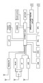
- FIG. 13 is an explanatory diagram illustrating an example of a hardware configuration of the antenna device according to the tenth embodiment.
- Antenna Device according to First Embodiment Antenna Device according to Second Embodiment 3. Antenna Device according to Third Embodiment 4. Antenna Device according to Fourth Embodiment 5. Antenna Device according to Fifth Embodiment 6. Antenna Device according to Sixth Embodiment 7. Antenna Device according to Seventh Embodiment 8. Antenna Device according to Eighth Embodiment 9. Antenna Device according to Ninth Embodiment 10. Antenna Device according to Tenth Embodiment 11. Antenna Device according to Eleventh Embodiment
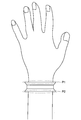
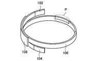
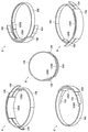
- FIG. 1 is an explanatory diagram illustrating an example of the structure of the antenna device according to the first embodiment.
- FIG. 1 A to E depict an example of the antenna device according to the first embodiment, from different angles.
- the first antenna 102 and the second antenna 104 are each configured, for example, by either one antenna element or a plurality of antenna elements, and serve to transmit and receive signals.
- the first antenna 102 and the second antenna 104 may be antennas of a same structure or antennas of different structures.
- the first antenna 102 and the second antenna 104 are, for example, an antenna for LTE and 3G, an antenna for a wireless local area network (WLAN), an antenna for communication in compliance with IEEE802.15.1 (hereinafter, sometimes referred to as "BT"), and an antenna for global positioning system (GPS). Also, the first antenna 102 and the second antenna 104 may be antennas of different communication methods, or antennas for a same communication method, for example.
- WLAN wireless local area network
- GPS global positioning system
- the first antenna 102 and the second antenna 104 may be antennas of different communication methods, or antennas for a same communication method, for example.
- the ground plate 106 is configured by one member or a plurality of members, for example.
- the ground plate 106 configured by a plurality of members is structured such that a plurality of members made of above material are joined together by a joint part 110 described later.
- the ground plate 106 is shaped in a spiral, to suppress increase of a diameter of a roll of the ground plate 106, while also elongating the length of the ground plate 106 in the longitudinal direction.
- the length of the ground plate 106 in the longitudinal direction is approximately 200 mm, which is equal to or more than 1/4 of a wavelength corresponding to 700 MHz that is the lowermost region of usable frequencies at least, and which corresponds to approximately 1/2 of the wavelength.
- the antenna device according to the first embodiment has antenna characteristics that satisfy a communication specification using a frequency from 700 MHz to 2700 MHz.
- the joint part 110 is provided at another part that is not the double winding part (P illustrated in FIG. 1 A, for example) in the ground plate 106.
- the joint part 110 is provided at the other part to make it easier for a user to adjust the length of the ground plate 106 in the longitudinal direction.
- the joint part 110 is made of material that allows a signal to be transmitted therethrough (for example, metal, etc.) for example, and has electrical conductivity.
- the ground plate 106 including the joint part 110 has electrical conductivity as a whole, to obtain antenna characteristics according to the length of the entire ground plate 106 in the longitudinal direction.
- the antenna device according to the first embodiment may be structured in such a manner that the joint part 110 does not have electrical conductivity, for example.
- the joint part 110 is made of material having low electrical conductivity or insulator as a whole or in part, for example.
- the joint part 110 limits the length in the longitudinal direction of the ground plate 106 that functions as a transmission path of a signal.
- the joint part 110 does not have electrical conductivity, so that the antenna device according to the first embodiment does not use the entire ground plate 106 for example (for example, so as to obtain antenna characteristics for communication using a comparatively high frequency).
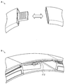
- FIG. 2 is an explanatory diagram illustrating an example of the structure of the joint part 110 according to the present embodiment.
- FIG. 2 illustrates an example of the structure of the joint part 110 having the spring terminals 112.
- FIG. 2 illustrates an example of the structure when the joint part 110 has electrical conductivity and a terminal of a USB (Universal Serial Bus) connector is utilized.
- USB Universal Serial Bus
- a dedicated terminal for contacting with the spring terminals 112 may be provided outside the USB connector, to form a transmission path of a signal between the dedicated terminal and the spring terminals 112.
- the joint part 110 according to the present embodiment includes a structure illustrated in FIG. 2, for example. Note that the structure of the joint part 110 according to the present embodiment is not limited to an example illustrated in FIG. 2, as a matter of course.
- the structure of the antenna device according to the present embodiment is not limited to the antenna device according to the above first embodiment (including the variant example. ditto in the following).
- another example of the structure of the antenna device according to the present embodiment will be described. Note that, in the following, different structure from the antenna device according to the above first embodiment will be described mainly, based on the structure of the antenna device according to the above first embodiment.
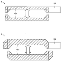
- FIG. 3 B illustrates an example of the gap between portions of the ground plate 106, which is made larger without changing the length of the ground plate 106 in the short direction at the double winding part of the ground plate 106.
- impedance rise at the double winding part of the ground plate 106 is suppressed, despite the size of the antenna device according to the second embodiment that is larger than the antenna device according to the first embodiment.
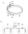
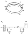
- the resonance frequency of the circuits 114 may be of one kind or a plurality of kinds.
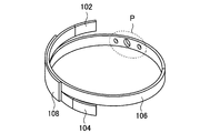
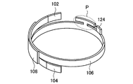
- the ground plate 106 included in the antenna device according to the seventh embodiment includes a third antenna (third antenna) formed as illustrated in P of FIG. 9.
- the third antenna according to the present embodiment is formed by transforming a part of the ground plate 106, for example.
- the antenna device includes a hardware illustrated below, for example.
- the hardware configuration of the antenna device according to the tenth embodiment is not limited to an example illustrated below, as a matter of course.
- Processors and various types of processing circuits a ROM (Read Only Memory) and a RAM (Random Access Memory), an IC having a storage medium such as a flash memory (for example, a system IC illustrated in FIG. 13)
- An operation interface that a user can operate for example, a touch sensor illustrated in FIG. 13
- a display device that displays various images on a display screen (for example, an LCD illustrated in FIG. 13)
- An input and output interface for example, USB and SDIO illustrated in FIG.
- An antenna device including: at least one antenna configured to transmit and receive communication signals; and a helix ground plate connected to the at least one antenna, wherein the helix ground plate includes an overlapping part, and has a length of at least one-quarter of a wavelength of a lowest-frequency in the communication signals.
Landscapes
- Engineering & Computer Science (AREA)
- Computer Networks & Wireless Communication (AREA)
- Support Of Aerials (AREA)
- Variable-Direction Aerials And Aerial Arrays (AREA)
Abstract
Un dispositif antenne comprend au moins une antenne qui transmet et reçoit des signaux de communication, et une plaque de mise à la terre en hélice connectée à l'au moins une antenne. La plaque de mise à la terre en hélice comprend une partie de chevauchement, et a une longueur d'au moins un quart d'une longueur d'onde de la plus basse fréquence dans les signaux de communication.
Priority Applications (3)
| Application Number | Priority Date | Filing Date | Title |
|---|---|---|---|
| EP15722361.1A EP3155487A1 (fr) | 2014-06-16 | 2015-04-22 | Dispositif antenne |
| CN201580030802.XA CN106463824B (zh) | 2014-06-16 | 2015-04-22 | 天线设备 |
| US15/308,469 US10256533B2 (en) | 2014-06-16 | 2015-04-22 | Antenna device |
Applications Claiming Priority (2)
| Application Number | Priority Date | Filing Date | Title |
|---|---|---|---|
| JP2014-123565 | 2014-06-16 | ||
| JP2014123565A JP6201906B2 (ja) | 2014-06-16 | 2014-06-16 | アンテナ装置 |
Publications (1)
| Publication Number | Publication Date |
|---|---|
| WO2015194083A1 true WO2015194083A1 (fr) | 2015-12-23 |
Family
ID=53177334
Family Applications (1)
| Application Number | Title | Priority Date | Filing Date |
|---|---|---|---|
| PCT/JP2015/002201 Ceased WO2015194083A1 (fr) | 2014-06-16 | 2015-04-22 | Dispositif antenne |
Country Status (5)
| Country | Link |
|---|---|
| US (1) | US10256533B2 (fr) |
| EP (1) | EP3155487A1 (fr) |
| JP (1) | JP6201906B2 (fr) |
| CN (1) | CN106463824B (fr) |
| WO (1) | WO2015194083A1 (fr) |
Cited By (1)
| Publication number | Priority date | Publication date | Assignee | Title |
|---|---|---|---|---|
| WO2018043921A1 (fr) * | 2016-08-29 | 2018-03-08 | Samsung Electronics Co., Ltd. | Dispositif portable comprenant une antenne multibande |
Families Citing this family (6)
| Publication number | Priority date | Publication date | Assignee | Title |
|---|---|---|---|---|
| US11050142B2 (en) | 2013-03-11 | 2021-06-29 | Suunto Oy | Coupled antenna structure |
| US11059550B2 (en) | 2013-03-11 | 2021-07-13 | Suunto Oy | Diving computer with coupled antenna and water contact assembly |
| CN107706548A (zh) * | 2017-09-27 | 2018-02-16 | 青岛海信移动通信技术股份有限公司 | 一种用于可穿戴设备的天线装置和可穿戴设备 |
| TWI790344B (zh) * | 2018-02-08 | 2023-01-21 | 芬蘭商順妥公司 | 槽孔模式天線 |
| TWI798344B (zh) | 2018-02-08 | 2023-04-11 | 芬蘭商順妥公司 | 槽孔模式天線 |
| JP6614387B1 (ja) * | 2019-05-09 | 2019-12-04 | パナソニックIpマネジメント株式会社 | マイクロストリップアンテナ及びウェアラブルセンサ端末 |
Citations (8)
| Publication number | Priority date | Publication date | Assignee | Title |
|---|---|---|---|---|
| US4754285A (en) * | 1987-05-01 | 1988-06-28 | Timex Corporation | Expansion band antenna for a wristwatch application |
| EP0279054A1 (fr) * | 1987-01-28 | 1988-08-24 | Timex Corporation | Bracelet flexible pour montre à antenne incorporée et procédé pour sa fabrication |
| US5008864A (en) * | 1990-02-15 | 1991-04-16 | Mitsubishi Denki Kabushiki Kaisha | Portable radio telephone device |
| EP1329985A2 (fr) * | 2002-01-18 | 2003-07-23 | Matsushita Electric Industrial Co., Ltd. | Dispositif d antenne, appareil de communication et méthode de conception d' un tel dispositif d' antenne |
| JP2009075138A (ja) | 2003-03-04 | 2009-04-09 | Seiko Epson Corp | 無線機能付き電子時計 |
| JP2011166820A (ja) | 2011-04-22 | 2011-08-25 | Casio Computer Co Ltd | 電子機器及び電子機器の製造方法 |
| US20120056792A1 (en) * | 2010-09-03 | 2012-03-08 | Hon Hai Precision Industry Co., Ltd. | Wearable device with antenna |
| JP2013030920A (ja) | 2011-07-27 | 2013-02-07 | Sharp Corp | 無線通信機 |
Family Cites Families (15)
| Publication number | Priority date | Publication date | Assignee | Title |
|---|---|---|---|---|
| US5134418A (en) * | 1990-06-04 | 1992-07-28 | Motorola, Inc. | Apparatus for sensing the integrity of a wristband antenna |
| EP1093098B1 (fr) * | 1999-10-11 | 2003-04-16 | Asulab S.A. | Structure formant antenne constituant par ailleurs un boítier blindé permettant notamment d'accueillir tout ou partie de l'électronique d'une unité portative de faible volume |
| US6366250B1 (en) * | 1999-12-09 | 2002-04-02 | Sirf Technology, Inc. | Wrist mounted wireless instrument and antenna apparatus |
| JP2003283238A (ja) * | 2002-01-18 | 2003-10-03 | Matsushita Electric Ind Co Ltd | アンテナ装置、通信装置、およびアンテナ装置設計方法 |
| JP2004266354A (ja) * | 2003-02-10 | 2004-09-24 | Casio Comput Co Ltd | 腕装着型通信装置 |
| JP4057494B2 (ja) * | 2003-08-29 | 2008-03-05 | 日本アンテナ株式会社 | スパイラルアンテナ |
| JP4234643B2 (ja) * | 2004-06-25 | 2009-03-04 | 株式会社日本自動車部品総合研究所 | 車載アンテナ |
| US8073548B2 (en) * | 2004-08-24 | 2011-12-06 | Sensors For Medicine And Science, Inc. | Wristband or other type of band having an adjustable antenna for use with a sensor reader |
| WO2006051113A1 (fr) * | 2004-11-12 | 2006-05-18 | Fractus, S.A. | Structure d’antenne pour un dispositif sans fil avec un plan de sol en forme de boucle |
| JP2008300897A (ja) * | 2007-05-29 | 2008-12-11 | Ngk Spark Plug Co Ltd | アンテナ装置 |
| JP4939309B2 (ja) * | 2007-06-04 | 2012-05-23 | 株式会社エヌ・ティ・ティ・ドコモ | アンテナ装置 |
| JP2011015345A (ja) * | 2009-07-06 | 2011-01-20 | Panasonic Corp | 携帯無線装置 |
| JP2013046141A (ja) * | 2011-08-23 | 2013-03-04 | Kyocera Corp | 無線通信端末 |
| US9825364B2 (en) * | 2014-06-12 | 2017-11-21 | Verily Life Sciences Llc | Adaptive antenna tuning based on measured antenna impedance |
| JP6775161B2 (ja) * | 2014-12-02 | 2020-10-28 | パナソニックIpマネジメント株式会社 | アンテナ装置 |
-
2014
- 2014-06-16 JP JP2014123565A patent/JP6201906B2/ja not_active Expired - Fee Related
-
2015
- 2015-04-22 EP EP15722361.1A patent/EP3155487A1/fr not_active Withdrawn
- 2015-04-22 WO PCT/JP2015/002201 patent/WO2015194083A1/fr not_active Ceased
- 2015-04-22 US US15/308,469 patent/US10256533B2/en not_active Expired - Fee Related
- 2015-04-22 CN CN201580030802.XA patent/CN106463824B/zh not_active Expired - Fee Related
Patent Citations (8)
| Publication number | Priority date | Publication date | Assignee | Title |
|---|---|---|---|---|
| EP0279054A1 (fr) * | 1987-01-28 | 1988-08-24 | Timex Corporation | Bracelet flexible pour montre à antenne incorporée et procédé pour sa fabrication |
| US4754285A (en) * | 1987-05-01 | 1988-06-28 | Timex Corporation | Expansion band antenna for a wristwatch application |
| US5008864A (en) * | 1990-02-15 | 1991-04-16 | Mitsubishi Denki Kabushiki Kaisha | Portable radio telephone device |
| EP1329985A2 (fr) * | 2002-01-18 | 2003-07-23 | Matsushita Electric Industrial Co., Ltd. | Dispositif d antenne, appareil de communication et méthode de conception d' un tel dispositif d' antenne |
| JP2009075138A (ja) | 2003-03-04 | 2009-04-09 | Seiko Epson Corp | 無線機能付き電子時計 |
| US20120056792A1 (en) * | 2010-09-03 | 2012-03-08 | Hon Hai Precision Industry Co., Ltd. | Wearable device with antenna |
| JP2011166820A (ja) | 2011-04-22 | 2011-08-25 | Casio Computer Co Ltd | 電子機器及び電子機器の製造方法 |
| JP2013030920A (ja) | 2011-07-27 | 2013-02-07 | Sharp Corp | 無線通信機 |
Cited By (3)
| Publication number | Priority date | Publication date | Assignee | Title |
|---|---|---|---|---|
| WO2018043921A1 (fr) * | 2016-08-29 | 2018-03-08 | Samsung Electronics Co., Ltd. | Dispositif portable comprenant une antenne multibande |
| US11095021B2 (en) | 2016-08-29 | 2021-08-17 | Samsung Electronics Co., Ltd | Wearable device including mutli-band antenna |
| US11955701B2 (en) | 2016-08-29 | 2024-04-09 | Samsung Electronics Co., Ltd | Wearable device including multi-band antenna |
Also Published As
| Publication number | Publication date |
|---|---|
| CN106463824A (zh) | 2017-02-22 |
| EP3155487A1 (fr) | 2017-04-19 |
| JP6201906B2 (ja) | 2017-09-27 |
| US20170062918A1 (en) | 2017-03-02 |
| JP2016005084A (ja) | 2016-01-12 |
| CN106463824B (zh) | 2020-05-19 |
| US10256533B2 (en) | 2019-04-09 |
Similar Documents
| Publication | Publication Date | Title |
|---|---|---|
| US10256533B2 (en) | Antenna device | |
| US11362687B2 (en) | Wireless communication device | |
| TWI661613B (zh) | 天線結構及具有該天線結構的無線通訊裝置 | |
| US9660326B2 (en) | Conductive loop antennas | |
| US10290940B2 (en) | Broadband switchable antenna | |
| WO2019090690A1 (fr) | Antenne de terminal mobile et terminal mobile | |
| TWI511380B (zh) | 通訊裝置 | |
| CN105720380B (zh) | 可调多频段天线和天线调试方法 | |
| CN105811079B (zh) | 一种天线装置及电子设备 | |
| CN107317095A (zh) | 一种天线系统及移动终端 | |
| WO2014117738A1 (fr) | Appareil d'antenne et dispositif terminal | |
| CN107394404A (zh) | 一种天线结构及移动终端 | |
| JP6775161B2 (ja) | アンテナ装置 | |
| CN105098354A (zh) | 移动终端及天线装置 | |
| CN107204509B (zh) | 电子设备及其天线结构 | |
| CN106099321A (zh) | 金属智能手表及其全频段调谐天线 | |
| US10686248B2 (en) | Wireless communication device | |
| CN204668473U (zh) | 一种多频段终端天线和电子设备 | |
| CN115528420B (zh) | 一种电子设备 | |
| EP4521635A1 (fr) | Mélangeur radiofréquence à courant de polarisation partagé | |
| JP2011193433A (ja) | 無線通信装置 | |
| WO2025064101A1 (fr) | Dispositif électronique à inducteurs tridimensionnels sur puce | |
| CN211045724U (zh) | 一种天线及移动终端 | |
| CN106785491B (zh) | 一种偶极双频天线和电子产品 | |
| TWI617082B (zh) | 無線通訊裝置 |
Legal Events
| Date | Code | Title | Description |
|---|---|---|---|
| 121 | Ep: the epo has been informed by wipo that ep was designated in this application |
Ref document number: 15722361 Country of ref document: EP Kind code of ref document: A1 |
|
| WWE | Wipo information: entry into national phase |
Ref document number: 15308469 Country of ref document: US |
|
| REEP | Request for entry into the european phase |
Ref document number: 2015722361 Country of ref document: EP |
|
| WWE | Wipo information: entry into national phase |
Ref document number: 2015722361 Country of ref document: EP |
|
| NENP | Non-entry into the national phase |
Ref country code: DE |