EP1330211B1 - Geflochtene, verzweigte, implantierbare vorrichtung und verfahren zu deren herstellung - Google Patents
Geflochtene, verzweigte, implantierbare vorrichtung und verfahren zu deren herstellung Download PDFInfo
- Publication number
- EP1330211B1 EP1330211B1 EP01975552A EP01975552A EP1330211B1 EP 1330211 B1 EP1330211 B1 EP 1330211B1 EP 01975552 A EP01975552 A EP 01975552A EP 01975552 A EP01975552 A EP 01975552A EP 1330211 B1 EP1330211 B1 EP 1330211B1
- Authority
- EP
- European Patent Office
- Prior art keywords
- stent
- graft
- braided
- leg
- braiding
- Prior art date
- Legal status (The legal status is an assumption and is not a legal conclusion. Google has not performed a legal analysis and makes no representation as to the accuracy of the status listed.)
- Expired - Lifetime
Links
Images









Classifications
-
- A—HUMAN NECESSITIES
- A61—MEDICAL OR VETERINARY SCIENCE; HYGIENE
- A61F—FILTERS IMPLANTABLE INTO BLOOD VESSELS; PROSTHESES; DEVICES PROVIDING PATENCY TO, OR PREVENTING COLLAPSING OF, TUBULAR STRUCTURES OF THE BODY, e.g. STENTS; ORTHOPAEDIC, NURSING OR CONTRACEPTIVE DEVICES; FOMENTATION; TREATMENT OR PROTECTION OF EYES OR EARS; BANDAGES, DRESSINGS OR ABSORBENT PADS; FIRST-AID KITS
- A61F2/00—Filters implantable into blood vessels; Prostheses, i.e. artificial substitutes or replacements for parts of the body; Appliances for connecting them with the body; Devices providing patency to, or preventing collapsing of, tubular structures of the body, e.g. stents
- A61F2/82—Devices providing patency to, or preventing collapsing of, tubular structures of the body, e.g. stents
- A61F2/86—Stents in a form characterised by the wire-like elements; Stents in the form characterised by a net-like or mesh-like structure
- A61F2/90—Stents in a form characterised by the wire-like elements; Stents in the form characterised by a net-like or mesh-like structure characterised by a net-like or mesh-like structure
-
- D—TEXTILES; PAPER
- D04—BRAIDING; LACE-MAKING; KNITTING; TRIMMINGS; NON-WOVEN FABRICS
- D04C—BRAIDING OR MANUFACTURE OF LACE, INCLUDING BOBBIN-NET OR CARBONISED LACE; BRAIDING MACHINES; BRAID; LACE
- D04C1/00—Braid or lace, e.g. pillow-lace; Processes for the manufacture thereof
- D04C1/06—Braid or lace serving particular purposes
-
- D—TEXTILES; PAPER
- D04—BRAIDING; LACE-MAKING; KNITTING; TRIMMINGS; NON-WOVEN FABRICS
- D04C—BRAIDING OR MANUFACTURE OF LACE, INCLUDING BOBBIN-NET OR CARBONISED LACE; BRAIDING MACHINES; BRAID; LACE
- D04C3/00—Braiding or lacing machines
- D04C3/40—Braiding or lacing machines for making tubular braids by circulating strand supplies around braiding centre at equal distances
-
- D—TEXTILES; PAPER
- D04—BRAIDING; LACE-MAKING; KNITTING; TRIMMINGS; NON-WOVEN FABRICS
- D04C—BRAIDING OR MANUFACTURE OF LACE, INCLUDING BOBBIN-NET OR CARBONISED LACE; BRAIDING MACHINES; BRAID; LACE
- D04C3/00—Braiding or lacing machines
- D04C3/48—Auxiliary devices
-
- A—HUMAN NECESSITIES
- A61—MEDICAL OR VETERINARY SCIENCE; HYGIENE
- A61F—FILTERS IMPLANTABLE INTO BLOOD VESSELS; PROSTHESES; DEVICES PROVIDING PATENCY TO, OR PREVENTING COLLAPSING OF, TUBULAR STRUCTURES OF THE BODY, e.g. STENTS; ORTHOPAEDIC, NURSING OR CONTRACEPTIVE DEVICES; FOMENTATION; TREATMENT OR PROTECTION OF EYES OR EARS; BANDAGES, DRESSINGS OR ABSORBENT PADS; FIRST-AID KITS
- A61F2/00—Filters implantable into blood vessels; Prostheses, i.e. artificial substitutes or replacements for parts of the body; Appliances for connecting them with the body; Devices providing patency to, or preventing collapsing of, tubular structures of the body, e.g. stents
- A61F2/02—Prostheses implantable into the body
- A61F2/04—Hollow or tubular parts of organs, e.g. bladders, tracheae, bronchi or bile ducts
- A61F2/06—Blood vessels
- A61F2/07—Stent-grafts
-
- A—HUMAN NECESSITIES
- A61—MEDICAL OR VETERINARY SCIENCE; HYGIENE
- A61F—FILTERS IMPLANTABLE INTO BLOOD VESSELS; PROSTHESES; DEVICES PROVIDING PATENCY TO, OR PREVENTING COLLAPSING OF, TUBULAR STRUCTURES OF THE BODY, e.g. STENTS; ORTHOPAEDIC, NURSING OR CONTRACEPTIVE DEVICES; FOMENTATION; TREATMENT OR PROTECTION OF EYES OR EARS; BANDAGES, DRESSINGS OR ABSORBENT PADS; FIRST-AID KITS
- A61F2/00—Filters implantable into blood vessels; Prostheses, i.e. artificial substitutes or replacements for parts of the body; Appliances for connecting them with the body; Devices providing patency to, or preventing collapsing of, tubular structures of the body, e.g. stents
- A61F2/02—Prostheses implantable into the body
- A61F2/04—Hollow or tubular parts of organs, e.g. bladders, tracheae, bronchi or bile ducts
- A61F2/06—Blood vessels
- A61F2002/065—Y-shaped blood vessels
-
- A—HUMAN NECESSITIES
- A61—MEDICAL OR VETERINARY SCIENCE; HYGIENE
- A61F—FILTERS IMPLANTABLE INTO BLOOD VESSELS; PROSTHESES; DEVICES PROVIDING PATENCY TO, OR PREVENTING COLLAPSING OF, TUBULAR STRUCTURES OF THE BODY, e.g. STENTS; ORTHOPAEDIC, NURSING OR CONTRACEPTIVE DEVICES; FOMENTATION; TREATMENT OR PROTECTION OF EYES OR EARS; BANDAGES, DRESSINGS OR ABSORBENT PADS; FIRST-AID KITS
- A61F2/00—Filters implantable into blood vessels; Prostheses, i.e. artificial substitutes or replacements for parts of the body; Appliances for connecting them with the body; Devices providing patency to, or preventing collapsing of, tubular structures of the body, e.g. stents
- A61F2/02—Prostheses implantable into the body
- A61F2/04—Hollow or tubular parts of organs, e.g. bladders, tracheae, bronchi or bile ducts
- A61F2/06—Blood vessels
- A61F2/07—Stent-grafts
- A61F2002/072—Encapsulated stents, e.g. wire or whole stent embedded in lining
-
- A—HUMAN NECESSITIES
- A61—MEDICAL OR VETERINARY SCIENCE; HYGIENE
- A61F—FILTERS IMPLANTABLE INTO BLOOD VESSELS; PROSTHESES; DEVICES PROVIDING PATENCY TO, OR PREVENTING COLLAPSING OF, TUBULAR STRUCTURES OF THE BODY, e.g. STENTS; ORTHOPAEDIC, NURSING OR CONTRACEPTIVE DEVICES; FOMENTATION; TREATMENT OR PROTECTION OF EYES OR EARS; BANDAGES, DRESSINGS OR ABSORBENT PADS; FIRST-AID KITS
- A61F2/00—Filters implantable into blood vessels; Prostheses, i.e. artificial substitutes or replacements for parts of the body; Appliances for connecting them with the body; Devices providing patency to, or preventing collapsing of, tubular structures of the body, e.g. stents
- A61F2/82—Devices providing patency to, or preventing collapsing of, tubular structures of the body, e.g. stents
- A61F2002/821—Ostial stents
-
- A—HUMAN NECESSITIES
- A61—MEDICAL OR VETERINARY SCIENCE; HYGIENE
- A61F—FILTERS IMPLANTABLE INTO BLOOD VESSELS; PROSTHESES; DEVICES PROVIDING PATENCY TO, OR PREVENTING COLLAPSING OF, TUBULAR STRUCTURES OF THE BODY, e.g. STENTS; ORTHOPAEDIC, NURSING OR CONTRACEPTIVE DEVICES; FOMENTATION; TREATMENT OR PROTECTION OF EYES OR EARS; BANDAGES, DRESSINGS OR ABSORBENT PADS; FIRST-AID KITS
- A61F2220/00—Fixations or connections for prostheses classified in groups A61F2/00 - A61F2/26 or A61F2/82 or A61F9/00 or A61F11/00 or subgroups thereof
- A61F2220/0008—Fixation appliances for connecting prostheses to the body
- A61F2220/0016—Fixation appliances for connecting prostheses to the body with sharp anchoring protrusions, e.g. barbs, pins, spikes
-
- A—HUMAN NECESSITIES
- A61—MEDICAL OR VETERINARY SCIENCE; HYGIENE
- A61F—FILTERS IMPLANTABLE INTO BLOOD VESSELS; PROSTHESES; DEVICES PROVIDING PATENCY TO, OR PREVENTING COLLAPSING OF, TUBULAR STRUCTURES OF THE BODY, e.g. STENTS; ORTHOPAEDIC, NURSING OR CONTRACEPTIVE DEVICES; FOMENTATION; TREATMENT OR PROTECTION OF EYES OR EARS; BANDAGES, DRESSINGS OR ABSORBENT PADS; FIRST-AID KITS
- A61F2220/00—Fixations or connections for prostheses classified in groups A61F2/00 - A61F2/26 or A61F2/82 or A61F9/00 or A61F11/00 or subgroups thereof
- A61F2220/0025—Connections or couplings between prosthetic parts, e.g. between modular parts; Connecting elements
- A61F2220/005—Connections or couplings between prosthetic parts, e.g. between modular parts; Connecting elements using adhesives
-
- A—HUMAN NECESSITIES
- A61—MEDICAL OR VETERINARY SCIENCE; HYGIENE
- A61F—FILTERS IMPLANTABLE INTO BLOOD VESSELS; PROSTHESES; DEVICES PROVIDING PATENCY TO, OR PREVENTING COLLAPSING OF, TUBULAR STRUCTURES OF THE BODY, e.g. STENTS; ORTHOPAEDIC, NURSING OR CONTRACEPTIVE DEVICES; FOMENTATION; TREATMENT OR PROTECTION OF EYES OR EARS; BANDAGES, DRESSINGS OR ABSORBENT PADS; FIRST-AID KITS
- A61F2220/00—Fixations or connections for prostheses classified in groups A61F2/00 - A61F2/26 or A61F2/82 or A61F9/00 or A61F11/00 or subgroups thereof
- A61F2220/0025—Connections or couplings between prosthetic parts, e.g. between modular parts; Connecting elements
- A61F2220/0066—Connections or couplings between prosthetic parts, e.g. between modular parts; Connecting elements stapled
-
- A—HUMAN NECESSITIES
- A61—MEDICAL OR VETERINARY SCIENCE; HYGIENE
- A61F—FILTERS IMPLANTABLE INTO BLOOD VESSELS; PROSTHESES; DEVICES PROVIDING PATENCY TO, OR PREVENTING COLLAPSING OF, TUBULAR STRUCTURES OF THE BODY, e.g. STENTS; ORTHOPAEDIC, NURSING OR CONTRACEPTIVE DEVICES; FOMENTATION; TREATMENT OR PROTECTION OF EYES OR EARS; BANDAGES, DRESSINGS OR ABSORBENT PADS; FIRST-AID KITS
- A61F2220/00—Fixations or connections for prostheses classified in groups A61F2/00 - A61F2/26 or A61F2/82 or A61F9/00 or A61F11/00 or subgroups thereof
- A61F2220/0025—Connections or couplings between prosthetic parts, e.g. between modular parts; Connecting elements
- A61F2220/0075—Connections or couplings between prosthetic parts, e.g. between modular parts; Connecting elements sutured, ligatured or stitched, retained or tied with a rope, string, thread, wire or cable
-
- A—HUMAN NECESSITIES
- A61—MEDICAL OR VETERINARY SCIENCE; HYGIENE
- A61F—FILTERS IMPLANTABLE INTO BLOOD VESSELS; PROSTHESES; DEVICES PROVIDING PATENCY TO, OR PREVENTING COLLAPSING OF, TUBULAR STRUCTURES OF THE BODY, e.g. STENTS; ORTHOPAEDIC, NURSING OR CONTRACEPTIVE DEVICES; FOMENTATION; TREATMENT OR PROTECTION OF EYES OR EARS; BANDAGES, DRESSINGS OR ABSORBENT PADS; FIRST-AID KITS
- A61F2230/00—Geometry of prostheses classified in groups A61F2/00 - A61F2/26 or A61F2/82 or A61F9/00 or A61F11/00 or subgroups thereof
- A61F2230/0002—Two-dimensional shapes, e.g. cross-sections
- A61F2230/0004—Rounded shapes, e.g. with rounded corners
- A61F2230/001—Figure-8-shaped, e.g. hourglass-shaped
-
- A—HUMAN NECESSITIES
- A61—MEDICAL OR VETERINARY SCIENCE; HYGIENE
- A61F—FILTERS IMPLANTABLE INTO BLOOD VESSELS; PROSTHESES; DEVICES PROVIDING PATENCY TO, OR PREVENTING COLLAPSING OF, TUBULAR STRUCTURES OF THE BODY, e.g. STENTS; ORTHOPAEDIC, NURSING OR CONTRACEPTIVE DEVICES; FOMENTATION; TREATMENT OR PROTECTION OF EYES OR EARS; BANDAGES, DRESSINGS OR ABSORBENT PADS; FIRST-AID KITS
- A61F2230/00—Geometry of prostheses classified in groups A61F2/00 - A61F2/26 or A61F2/82 or A61F9/00 or A61F11/00 or subgroups thereof
- A61F2230/0063—Three-dimensional shapes
- A61F2230/0067—Three-dimensional shapes conical
-
- A—HUMAN NECESSITIES
- A61—MEDICAL OR VETERINARY SCIENCE; HYGIENE
- A61F—FILTERS IMPLANTABLE INTO BLOOD VESSELS; PROSTHESES; DEVICES PROVIDING PATENCY TO, OR PREVENTING COLLAPSING OF, TUBULAR STRUCTURES OF THE BODY, e.g. STENTS; ORTHOPAEDIC, NURSING OR CONTRACEPTIVE DEVICES; FOMENTATION; TREATMENT OR PROTECTION OF EYES OR EARS; BANDAGES, DRESSINGS OR ABSORBENT PADS; FIRST-AID KITS
- A61F2250/00—Special features of prostheses classified in groups A61F2/00 - A61F2/26 or A61F2/82 or A61F9/00 or A61F11/00 or subgroups thereof
- A61F2250/0014—Special features of prostheses classified in groups A61F2/00 - A61F2/26 or A61F2/82 or A61F9/00 or A61F11/00 or subgroups thereof having different values of a given property or geometrical feature, e.g. mechanical property or material property, at different locations within the same prosthesis
- A61F2250/0036—Special features of prostheses classified in groups A61F2/00 - A61F2/26 or A61F2/82 or A61F9/00 or A61F11/00 or subgroups thereof having different values of a given property or geometrical feature, e.g. mechanical property or material property, at different locations within the same prosthesis differing in thickness
-
- A—HUMAN NECESSITIES
- A61—MEDICAL OR VETERINARY SCIENCE; HYGIENE
- A61F—FILTERS IMPLANTABLE INTO BLOOD VESSELS; PROSTHESES; DEVICES PROVIDING PATENCY TO, OR PREVENTING COLLAPSING OF, TUBULAR STRUCTURES OF THE BODY, e.g. STENTS; ORTHOPAEDIC, NURSING OR CONTRACEPTIVE DEVICES; FOMENTATION; TREATMENT OR PROTECTION OF EYES OR EARS; BANDAGES, DRESSINGS OR ABSORBENT PADS; FIRST-AID KITS
- A61F2250/00—Special features of prostheses classified in groups A61F2/00 - A61F2/26 or A61F2/82 or A61F9/00 or A61F11/00 or subgroups thereof
- A61F2250/0014—Special features of prostheses classified in groups A61F2/00 - A61F2/26 or A61F2/82 or A61F9/00 or A61F11/00 or subgroups thereof having different values of a given property or geometrical feature, e.g. mechanical property or material property, at different locations within the same prosthesis
- A61F2250/0039—Special features of prostheses classified in groups A61F2/00 - A61F2/26 or A61F2/82 or A61F9/00 or A61F11/00 or subgroups thereof having different values of a given property or geometrical feature, e.g. mechanical property or material property, at different locations within the same prosthesis differing in diameter
-
- D—TEXTILES; PAPER
- D10—INDEXING SCHEME ASSOCIATED WITH SUBLASSES OF SECTION D, RELATING TO TEXTILES
- D10B—INDEXING SCHEME ASSOCIATED WITH SUBLASSES OF SECTION D, RELATING TO TEXTILES
- D10B2509/00—Medical; Hygiene
- D10B2509/06—Vascular grafts; stents
Definitions
- This invention relates generally to endoluminal stents, grafts, and/or prostheses and, more specifically, to braided implantable devices adapted for deployment in branched lumina and processes for their manufacture.
- a stent is an elongated device used to support an intraluminal wall.
- a stent provides an unobstructed conduit for blood in the area of the stenosis.
- Such a stent may also have a prosthetic graft layer of fabric or covering lining the inside or outside thereof, such a covered stent being commonly referred to in the art as an intraluminal prosthesis, an endoluminal or endovascular graft (EVG), or a stent-graft.
- EVG endoluminal or endovascular graft
- a prosthesis may be used, for example, to treat a vascular aneurysm by removing the pressure on a weakened part of an artery so as to reduce the risk of rupture.
- a prosthesis is implanted in a blood vessel at the site of a stenosis or aneurysm endoluminally, i.e. by so-called “minimally invasive techniques” in which the prosthesis, restrained in a radially compressed configuration by a sheath or catheter, is delivered by a deployment system or "introducer" to the site where it is required.
- the introducer may enter the body through the patient's skin, or by a "cut down" technique in which the entry blood vessel is exposed by minor surgical means.
- the introducer When the introducer has been threaded into the body lumen to the prosthesis deployment location, the introducer is manipulated to cause the prosthesis to be ejected from the surrounding sheath or catheter in which it is restrained (or alternatively the surrounding sheath or catheter is retracted from the prosthesis), whereupon the prosthesis expands to a predetermined diameter at the deployment location, and the introducer is withdrawn.
- Stent expansion may be effected by spring elasticity, balloon expansion, or by the self-expansion of a thermally or stress-induced return of a memory material to a pre-conditioned expanded configuration.
- stent architectures are known in the art, including many designs comprising a filament or number of filaments, such as a wire or wires, wound or braided into a particular configuration. Included among these wire stent configurations are braided stents, such as is described in U.S. Patent No. 4,655,771 to Hans I. Wallsten, the '771 Wallsten patent being only one example of many variations of braided stents known in the art and thus not intended as a limitation of the invention described herein later. Braided stents tend to be very flexible, having the ability to be placed in tortuous anatomy and still maintain patency. The flexibility of braided stents make them particularly well-suited for treating aneurysms in the aorta, where the lumen of the vessel often becomes contorted and irregular both before and after placement of the stent.
- Braided grafts are also known in the art.
- U.S. Patents Nos. 5,718,159, 5,758,562, and 6,019,786 to Thompson and 5,957,974 to Thompson et al. (hereinafter "the Thompson patents"), describe braided graft structures, composite braided stent/graft structures having wire stent filaments interwoven with fabric graft yarns, and processes for their manufacture.
- other braiding technologies are known in the art, although not typically associated with the fabrication of implantable medical devices.
- U.S. Patent No. 4,881,444 to Konrad Krauland
- U.S. Patent No. 4,885,973 to Raymond Spain and U.S.
- Patent No. 4,621,560 to Brown et al. generally describe 3-dimensional braiding equipment and processes, also referred to as Cartesian braiding or jacquard braiding.
- Such braiding technology is typically used to make fiber-reinforced structural members, where, for example, fibrous structures are braided and then coated with a resin that hardens, providing a structure wherein the fibers provide tensile strength and the hardened resin provides compressive strength.
- stent-grafts for deployment in bifurcated lumen, such as for repair of abdominal aortic aneurysms (AAA).
- AAA abdominal aortic aneurysms
- Various stent-graft configurations are known in the art for bifurcated applications, including single-piece and modular designs, graft designs fully supported by stents, and graft designs only partially supported by stents.
- Figs. 1A and 1B there are shown the components of a modular, non-braided, bifurcated, stent 10 for use with a fully-supported graft as is fully described in U.S.
- stent 10 comprises a main body 12 which bifurcates into a first frustoconical leg transition 14 with a dependent first leg 16, and a second frustoconical leg transition 18.
- Second leg 20 is a modular component comprising a frustoconical part 22 adapted to interlock within second leg transition 18, and a depending portion 24.
- Frustoconical part 22 may have barbs 23 to help firmly connect second leg 20 to leg transition 18.
- such a bifurcated stent 10 is typically implanted within the vasculature such that the main body 12 and leg transitions 14 and 18 are positioned within the aorta main portion 26 and with the dependent first leg 16 and depending portion 24 of second leg 20 each positioned within respective iliac arteries 28 and 30.
- Modular designs are also available wherein both legs are modular components. All of the bifurcated stents described herein, regardless of underlying structure, generally resemble the configuration shown in Fig. 2 when fully implanted.
- the structure of stent 10 is a continuous wire zig-zag structure comprising a series of struts 32 joined at apices 34 and wound into hoops 36, with abutting hoops joined together in some manner, such as with sutures, at abutting apices.
- zig-zag stent architecture One potential disadvantage of zig-zag stent architecture is that the apices of the zig-zag structure can rub against the graft, causing wear in the graft.
- Modular, fully-supported, bifurcated stent-graft designs using braided architecture are also known. Such designs typically comprise a tubular stent and/or graft that is crimped or pinched together in the middle or at one end to form a septum and two smaller lumina. These two lumina can then be used as sockets for the iliac sections.
- the braided stents have the advantage of being very adaptable to tortuous anatomy as compared to other stent architectures. The formation of the crimp, however, can cause metal cold-work and embrittlement in the stent wires and can result in bulkiness in the bifurcation region, requiring a relatively larger deployment profile than other designs.
- one-piece or "unitary" stent designs may be fully supported or only partially supported, such as by having anchoring stent portions only located at the end sections adjacent each opening of the graft.
- One piece stent designs having a zig-zag stent architecture still have the same disadvantage of potential graft wear due to rubbing of the apices.
- One-piece graft designs that are only partially supported have the potential disadvantage that the differences in radial strength and flexibility between the unsupported and supported regions make the stent-grafts susceptible to kinking when navigating through tortuous lumina.
- the invention comprises a branching implantable device for deployment in a lumen.
- the device comprises a body that branches into a plurality of legs, wherein at least a first leg portion of each leg comprises a discrete plurality of continuous strands braided together and at least a first body portion of the body comprises at least one of said continuous strands from each discrete plurality of continuous strands braided together.
- the device comprises a graft comprising a plurality of fabric yarns, or may comprise a composite stent-graft comprising a plurality of fabric yarns interbraided with a plurality of structural stent filaments.
- a method for treating a diseased branched lumen comprising a main section that branches into a plurality of branches.
- the method comprises the step of deploying within the branched lumen a branching implantable device of the invention comprising a body that branches into a plurality of legs. At least a first leg portion of each leg comprises a discrete plurality of continuous strands braided together. At least a first body portion of the body comprises at least one of said continuous strands from each discrete plurality of continuous strands braided together.
- the deployment step comprises deploying the body in the main section and deploying each leg within one of the branches.
- the invention further comprises a process for constructing a braided, branched implantable device having a body and a plurality of legs, each leg comprising a discrete plurality of strands.
- the process comprises the steps of braiding a first plurality of continuous strands to individually form at least a portion of a first leg; braiding at least a second plurality of continuous strands to individually form at least a portion of a second leg; and braiding at least one strand from each of the first plurality of continuous strands and the second plurality of continuous strands together to form at least a portion of the body.
- the legs may be formed sequentially before the body, or vice versa.
- the steps may be performed using circular braiding equipment, in which case the first leg may be formed sequentially before the second leg.
- the steps may also be performed using cartesian braiding equipment, in which case the legs may be formed simultaneously.
- implantable device 50 is a stent comprising a trunk section 52, a first iliac leg 54 and a second iliac leg 56.
- Stent 50 as shown in Fig. 3 is a unitary stent. That is, iliac legs 54 and 56 are continuous with trunk section 52, unlike modular stent designs in which two or more stent segments are assembled together to form the various parts of the stent (e.g., the trunk section and the two legs).
- the term "unitary" means a device having portions of each of its various parts made as a single unit.
- a unitary device contemplates a device whose entire length of all of its parts are made as a single unit, without the need to attach additional segments upon deployment.
- a unitary device may be used in conjunction with additional segments, if it is desired to attach such segments to either the legs or the trunk section upon deployment.
- unitary stent 50 as shown in Fig. 3 is merely one exemplary embodiment, and that this invention is applicable to "modular", braided stents and stent-grafts as well.
- module means a device having at least two discrete portions adapted for assembly in situ.
- one type of exemplary modular bifurcated device may include a trunk section that bifurcates into a single leg on one side adapted to extend into one iliac, and a socket on the other side, with the other leg being a modular piece adapted to be inserted into the socket, similar to the configuration shown in Figs. 1A and 1B.
- FIG. 1 Another type of modular bifurcated device may comprise only a trunk section with a bifurcated region that terminates is two short sockets into which two discrete leg members are adapted to be inserted.
- FIG. 3 Another type of modular bifurcated device may comprise only a trunk section with a bifurcated region that terminates is two short sockets into which two discrete leg members are adapted to be inserted.
- leg as used herein with respect to a device having a body portion and leg portions may refer to a full, integral leg adapted to, for example, extending into an iliac artery, or may refer to a socket portion of a leg adapted to receive a modular leg element.
- the invention as illustrated and described herein primarily references full leg structures, each of the methods and structures described herein is equally applicable to partial leg structures such as sockets for receiving modular leg elements.
- a typical braided device comprises a first set of strands 58L wound in a first helical direction (to the left as shown in Fig. 3) and a second set of strands 58R wound in a second, opposite helical direction (to the right as shown in Fig. 3), forming a plurality of overlaps 55.
- strand is a generic term referring either to an elongated wire filament (typically metal) or an elongated fibrous yarn, with each strand representing one of the elements which are braided with other strands to form the device of the present invention.
- Strands 58L and 58R may be wire filaments, such as nitinol or stainless steel, or may comprise polymer or any type of filaments known in the art.
- the strands may comprise yarns made from one or more materials from the group including but not limited to polyethyleneterepthalate (PET), polyetheretherketone (PEEK), polysulfone, polytetrafluroethylene (PTFE), expanded polytetrafluroethylene (ePTFE), fluorinated ethylene propylene (FEP), polycarbonate urethane, a polyolefin (such as polypropylene, polyethylene, or high density polyethylene (HDPE)), silicone, and polyurethane.
- the yarns may comprise monofilaments or multifilament yarns, either with round or non-round cross-section, and multifilament yarns may comprise twisted or untwisted filaments.
- filament is essentially synonymous with “strand” in the context of wires. With respect to fabrics, however, the term “filament” represents a single component of a multifilament yarn or the sole component of a monofilament yarn.
- a "braided" device refers to a device formed of at least two continuous strands which are interwoven in a pattern, thus forming overlaps 55, as shown in Fig. 3. At each overlap, one strand is positioned radially outward relative to the other strand. Following each strand along its helical path through a series of consecutive overlaps, that strand may, for example be in the radial inward position in one overlap and in the radial outward position in a next overlap, or may in the inward position for two overlaps and in the outward position for the next two, and so on.
- exemplary braided stents are disclosed in U.S. Patent No. 4,655,771 to Hans I. Wallsten.
- a typical braided stent is formed on a mandrel by a braiding or plaiting machine, such as a standard braiding machine known in the art and manufactured by Rotek of Ormond Beach, Florida. Any such braiding or plaiting machine may be used, however, and the use of terminology specific to components of the machine manufactured by Rotek is not intended as a limitation to the use of that machine design. To the extent that the terminology used herein is specific to the components of any one or several machines, it should be understood such components specifically referred to herein generally have corresponding functionally equivalent components with respect to other machines. Thus, the scope of the method described and claimed herein for braiding the device of present invention is not intended to be limited to the specific machine embodiment described herein, but extends to functionally equivalent machines also. In particular, Cartesian or jacquard braiding machines and methods, such as are described in U.S. Patent Nos. 4,885,973, 4,881,444, and 4,621,560, may also be used to manufacture implantable devices in accordance with this invention.
- Braiding machines can be used for manufacturing the device of the present invention about an exemplary modular mandrel as shown in Figs. 4A-C.
- Modular mandrel 60 as shown from the front in Fig. 4A and from the side in Fig. 4B, comprises a large diameter trunk section 62 and two, smaller diameter leg sections 64 L and 64 R .
- Leg sections 64 may comprise a male connector 66, as shown in Fig. 4B, which mates with a female receptacle 67 in trunk section 62 as shown in Figs. 4B and 4C.
- Hidden lines are not shown in Fig. 4A.
- the female receptacle may be on leg sections 64 L and 64 R and the male connector on trunk section 62.
- Connector 66 and receptacle 68 may be threaded, may comprise slip fittings, or may otherwise enable leg sections 64 L and 64 R to be releasably connected trunk section 62.
- Tapered recess 69 serves to model the device gradually to the different diameters of an aorta and iliac arteries.
- braiding machine 70 is shown schematically as typically comprising a number of notch gears 72 arranged in a circle.
- Machine 70 shown in Figs. 5A-F has twenty such notch gears 72, each notch gear adapted to rotate in the opposite direction as its neighboring notch gears, as illustrated by arrows A and B.
- This counter-rotation passes bobbin carriers 71, and the bobbins 74 mounted thereon, in a sinusoidal fashion from gear to gear, thus causing the bobbins to revolve about a longitudinal axis on which the circle is centered.
- the configuration of the notch gears, bobbin carriers, and bobbins to achieve this movement are well-known in the art, and an example of such a configuration is found in the braiding machine manufactured by Rotek.
- Each bobbin comprises strand 75 wound thereon.
- the bobbin carrier and bobbin typically interface in a way that helps keep the strand unraveling from the bobbin under proper tension, as is known in the art.
- the motion of the bobbins is described herein, it should be understood that the bobbins 74 are moved by virtue of being mounted on bobbin carriers 71.
- bobbin carriers 71 are shown in Fig. 5A, for example, each bobbin 74 also is mounted upon a bobbin carrier, creating a "loaded" bobbin carrier.
- the underlying bobbin carrier is not shown for carriers-loaded with bobbins 74.
- Bobbins 74L shown in Fig.
- the mandrel around which braided device 50 is formed is moved in a controlled manner substantially along a longitudinal axis about which the circle of notch gears 72 is centered and about which the bobbin carriers 71 revolve.
- wires 75 extend from braiding machine 70 to mandrel 64 in a conical configuration, as shown in Fig. 6.
- their respective strands form an overlap such that the strand from the bobbin on the outer radius 76 is disposed radially outward (with respect to the axis of the stent being assembled) relative to the strand from the bobbin on the inner radius 78.
- the space contained within the cone formed by the strands extending between the bobbins and the mandrel and including the space occupied by the mandrel is referred to herein as the "braiding zone" 90.
- ⁇ 1 and ⁇ 2 of the strand to the mandrel may be varied as desired, ⁇ 1 and ⁇ 2 preferably each comprise an angle of approximately 55° when the braiding angle of a braided stent ⁇ is approximately 110°. This angle may vary dependent upon the exact radial position of the bobbin relative to the mandrel and whether the strand is on the inside radial position or outside radial position on an overlap.
- angle ⁇ 1 is slightly larger than angle ⁇ 2 .
- the phrase "substantially along the longitudinal axis" as used with respect to the alignment of the moving mandrel means that the mandrel does not have to be perfectly centered in the braiding zone, but merely needs to be aligned close enough to the longitudinal axis that the angles of the strands between the mandrel and the bobbins allows the braiding operation to create a functional braid without tangling the strands.
- Mandrel leg sections 64 L and 64 R may therefore each comprise a puller interface 68 for attaching a "puller” adapted to pull the mandrel away from the circle of notch gears 72 at a controlled rate as the braid is formed.
- puller interface 68 may be a drilled and tapped hole 68 in mandrel 64R as shown in Fig. 4B, and the puller may be a metal rod that has a threaded end or slip fitting adapted to be threaded or otherwise locked into the hole.
- the puller rod may be retracted away from the circle, for example, by a set of counter-rotating caterpillar tracks which hold the rod therebetween and move the rod in a controlled manner.
- the circle of notch gears 72 can be considered to have an outer radius 76 (on which bobbins 74R are positioned in Fig. 5A) and an inner radius 78 (on which bobbins 74L are positioned in Fig. 5A).
- each bobbin 74L crosses over one bobbin 74R while on outer radius 76 before returning to inner radius 78 and crossing under another bobbin 74R.
- the braid created by such a weave can be said to have a 1:1 single strand braiding ratio (because each single strand crosses under another single strand, then over one, then under one, and so on).
- the 1:1 single strand braiding ratio is illustrated in Fig. 15A.
- the difference between angle ⁇ 1 and ⁇ 2 is sufficient to assure that the strands clear one another without tangling.
- strands 75 extending from bobbins 74 can be secured to the end of the mandrel in almost any manner, such as by taping them or tying them, and do not even have to be kept in any particular orientation.
- all the strands may all be taped or tied to a single point on one side of the mandrel.
- the braiding machine starts, it will stabilize into the proper braid configuration after only a few circumferential hoops of overlaps 55 (shown in Fig. 3) are formed.
- the portion between the proper configuration and the end can either be cut away as scrap or unbraided and then manipulated to form a non-braided end winding, as is discussed herein later.
- the ends of strands 75 may be wound around pins (not shown) or otherwise secured to the mandrel in a spaced circumferential configuration similar to the configuration of bobbins 74 in braiding machine 70.
- the braiding machine is first loaded as shown in Fig. 5A with a first portion 73 of a predetermined number of bobbins 74.
- the predetermined number of bobbins may comprise the maximum capacity of the machine and first portion 73 may, for example, comprise half of the bobbin capacity of the machine.
- the braiding operation is then performed as described above to form a first leg section of the braided stent around a first leg mandrel, for example leg mandrel 64R (either 64L or 64R may be the first leg mandrel, in which case the other is the second leg mandrel).
- leg mandrel 64R either 64L or 64R may be the first leg mandrel, in which case the other is the second leg mandrel.
- bobbins 74 of first portion 73 can be regrouped to one side (the right side as shown in Fig. 5B) of the circle of notch gears 72.
- the method for moving the bobbins may be by any of a number of ways.
- certain bobbin carriers may comprise closed eyelets through which the wire is threaded, in which case the entire bobbin carrier may be removed.
- Other bobbin carriers such as those manufactured, for example, by the Wardwell Braiding Machine Company of Central Falls, RI, comprise open, curled guides resembling a "pigtail" such that the bobbins may be simply unlocked and lifted off of their respective bobbin carriers and the strand readily removed from the guide.
- removing or replacing "the bobbins" on and off of the machine may comprise removing or replacing the bobbins only or the bobbins as still attached to the bobbin carriers.
- the quick-connect fitting may comprise any number of means well-known in the art for providing an interlocking engagement of one element with another, such as a magnetic connection, a twist-and-lock connection, a spring-loaded ball in channel connection, a lever-controlled cam connection, or any connection known in the art.
- the configuration shown in Figs. 14A and 14B is provided merely to show one example of such a quick-connection device. Any quick connection device may be used, however, and the invention is by no means limited to the use of the configuration shown in Figs. 14A and 14B.
- Exemplary quick disconnect comprises a male component 140 (shown in Fig. 14A) attached to bobbin carrier base 142 and a female component 141 (shown in Fig. 14B), typically attached to the bobbin carrier footplate (not shown) that rides along the notch gears (not shown) of the braiding machine (not shown).
- Male component 140 comprises a cylindrical post 144 and a cylindrical pin 145 inserted perpendicular to and through the post.
- a helical spring 146 extends about post 144 from pin 145 to bobbin carrier base 142.
- the bobbin carrier typically attaches to male component 140 on the surface (not shown) of bobbin carrier base 142 opposite post 144.
- Female component 141 comprises a base 148 having therein a cavity 147 having an X-shaped entryway 149 adapted to accept the post and the pin in one of two orientations.
- post 144 and pin 145 are inserted in cavity 149 and spring 146 is compressed while the male component is turned 1/8 of a full revolution such that the pin is positioned in accordance with indent 150 shown in dashed outline in Fig. 14B.
- the spring 146 biases pin 145 against indent 150 in the cavity wall such that the post and pin cannot rotate unless the spring is compressed further.
- the X-shape of the entryway 149 allows male component 140 to either be inserted and turned to the right or inserted and turned to the left, depending upon which side of the X the pin is inserted into. To disconnect the components, then, male component 140 may merely be manipulated to compress spring 146 and then turned 1/8 of a revolution either to the left or the right so that the pin can exit the cavity through the X-shaped entryway.
- base 148 of female component 141 may comprise a block of metal machined to create cavity 149 and indent 150 and then attached to the bobbin carrier footplate, such as with screws 151.
- the bobbin regrouping process can be essentially understood by comparing Figs. 5A and 5B.
- the bobbins Prior to bobbin regrouping, the bobbins are configured as shown in Fig. 5A, with pairs of bobbins I, II, III, and IV positioned relative to one another as shown.
- pair III remains in place, and the remaining bobbins are moved such that there are no empty bobbin carriers between pairs of loaded bobbin carriers in the loaded portion of the circle of notch gears 72, as shown in Fig. 5B.
- pairs I, II, and IV move from the positions shown in Fig. 5A to the positions shown in Fig. 5B.
- Bobbin carriers 71L can be said to form a first set of bobbin carriers that traverse the circle of notch gears 72 in the counter-clockwise direction, whereas bobbin carriers 71R form a second set of bobbin carriers that traverse the circle in the clockwise direction.
- bobbin 74L that rests on a bobbin carrier 71L before regrouping, to also reside on a bobbin carrier 71L after regrouping. Where the entire bobbin carrier is removed, it is desirable for the bobbin carrier to be replaced in a position where it travels in the same direction as it traveled prior to removal.
- bobbin 74 (or bobbin/bobbin carrier combination) on inner radius 78 may need to be switched with the bobbin (or bobbin/bobbin carrier combination) on outer radius 76 for every alternating pair of bobbins. So, for pairs of bobbins I, II, III, and IV shown in Fig.
- each notch gear 72 having a clockwise-rotating bobbin 74R on outer radius 76 has neighboring notch gears on either side with the clockwise-rotating bobbin on inner radius 78.
- bobbin carriers 71L may travel clockwise instead of counter-clockwise, with carriers 71R and bobbins 74R travelling counter-clockwise. It may be preferable, however, for the tangent of the wire to the bobbin to be on the same side of the bobbin as on the mandrel so that the wire is wound on the same helical direction on the mandrel as it was on the bobbin. For example, as shown in Fig.
- the wire originating from bobbin 74R is tangent to the right side of both the bobbin and mandrel 64R, and likewise the wire originating from bobbin 74L is tangent to the left side of both the bobbin and mandrel.
- first portion 73 of the predetermined number of bobbins 74 is removed and put aside, along with the completed leg braid still on leg mandrel 64R.
- the bobbins (or bobbin carriers) may be stored on a rack 80 so that the bobbins maintain the correct orientation and do not get tangled while they are set aside.
- the rack may take any form, from a configuration that mimics the configuration of the circle of notch gears 72 to a linear configuration wherein each place for holding a bobbin is easily identified with a corresponding position in the circle. For example, as shown in Fig.
- the rack may comprise a 10-row by 2-column array, columns C 76 and C 78 corresponding to outer radius 76 and inner radius 78 of machine 70, respectively, and rows R i -R x corresponding to pairs of bobbins i-x on machine 70.
- the bobbin on outer radius 76 of pair i is placed on row R i
- the bobbin on inner radius 78 of pair x is placed on row R x , column C 78 , and so on.
- a second leg is then braided about leg mandrel 64L with a second portion 77 of the predetermined number of bobbins 74 in the same manner as the first leg, except this time, after the leg has been braided, the second portion 77 is regrouped to the opposite side (the left side as shown in Fig. 5C) of the circle of notch gears 72.
- the first portion 73 of bobbins has a first discrete plurality of continuous strands associated with it while the second portion 77 has a second discrete plurality of continuous strands associated with it.
- each leg 54 and 56 is individually braided and comprises a discrete plurality of continuous strands, such that each leg consists of strands that are separate entities relative to the strands of the other leg.
- first portion 73 is returned to the machine, and leg mandrel 64R and the braid thereon are positioned alongside the second leg mandrel 64L as shown in Fig. 5D.
- the two mandrels are then attached to trunk section mandrel 62 as shown in Fig. 5E.
- first portion 73 returned to braiding machine 70 each bobbin carrier on the machine now has a bobbin mounted thereon.
- the braiding operation continues, now with all forty bobbins traversing the circle of notch gears 72 to create a braid around trunk section mandrel 62.
- the trunk portion may comprise more than all the strands from the two portions 73 and 77. It is only necessary that at least one continuous strand from each discrete plurality of continuous strands extend into the trunk portion, although it is preferred that at least half of each do so, and most preferred that all of them do so.
- portions 73 and 77 as illustrated herein each comprise half of the total number of bobbins. It may be desirable in certain applications, however, for one leg to have more strands in it than the other, such as if one leg has a greater diameter than the other. In such a case, portions 73 and 77 may be unequal.
- a variation on the above method may eliminate the step of regrouping the bobbins to one side of the circle of notch gears 72 before removing first portion 73 of the predetermined number of bobbins 74.
- first portion 73 is merely removed from the circle without regrouping, such as in the position shown in Fig. 5A, and stored.
- second portion 77 of the predetermined number of bobbins 74 is then left in a spaced configuration similar to that shown in Fig. 5F, and the first portion 73 is merely inserted to fill the gaps between the second portion 77.
- Trunk section mandrel 62 is then attached to leg mandrels 64L and 64R and the winding continues as described above. This method produces a device such as is shown in Fig. 8.
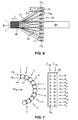
- the strands are braided in a 2:2 single strand braiding ratio with the machine at full capacity as shown in Fig. 5E.
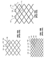
- a 2:2 single strand braiding ratio is illustrated in Fig. 15B wherein, for example, following consecutive overlaps of single strand 152 wound in a first helical direction, the strand travels over two oppositely-wound strands 153 and 154 at overlaps 155 and 156, respectively, and then travels under two strands 157 and 158 at overlaps 159 and 160, respectively, and so on. This is true of each strand in the braid.
- Fig. 15B wherein, for example, following consecutive overlaps of single strand 152 wound in a first helical direction, the strand travels over two oppositely-wound strands 153 and 154 at overlaps 155 and 156, respectively, and then travels under two strands 157 and 158 at overlaps 159 and 160, respectively, and so on. This is true of each strand in the
- 15A illustrates a 1:1 single strand braiding ratio, wherein following consecutive overlaps of strand 161 wound in a first helical direction, the single strand travels over one oppositely-wound strand 162 at overlap 163 and then travels under strand 164 at overlap 165, and so on.
- a plurality of machines may be used.
- a first machine may be used only for braiding leg sections. After each leg section is braided on the first machine, the bobbins may then be removed such as onto a rack as described above, and ported to a second machine. The second machine may be used for combining together two or more pre-braided leg sections.
- the stent may be manufactured using braiding machines having a different number of notch gears or using a different percentage of the capacity when winding, thus allowing preparation of stents having a 1:1 single strand braiding ratio throughout as described below, a 1:1 paired strand braiding ratio as shown in Fig. 15C and described below, or other configurations as desired.
- the exact braiding configuration is not intended as a limitation upon this invention.
- the illustrations in Figs. 15A-C are intended only to depict the general braiding configurations of the strands in relation to one another, and do not necessarily represent the actual number of strands or the precise look of an actual device.
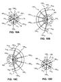
- a 24-carrier braiding machine 180 having twelve notch gears 72 is used to braid left leg 64L in a 1:1 braiding ratio as shown in Fig. 18A, ending with the bobbins configured in bobbin pairs 184i-vi as shown. For the left leg, these bobbin pairs 184i-vi are then transferred to a semicircular rack 182L in the positions shown.
- Braiding machine 180 may be separated from bobbin pairs 184i-vi and then used to braid a right leg 64R as shown in Fig. 18D.
- a second 24-carrier braiding machine may be used to braid right leg 64R.
- a second braiding machine adapted to accommodate greater or less than 24 carriers may be used, and the number of bobbins loaded on the machine may be less than or greater than the number used to form left leg 64L.
- bobbin pairs 186i-vi are transferred to semicircular rack 182R as shown in Fig.
- rack 182R may merely be an identical rack or even the same rack as rack 182L, merely oriented differently before being loaded with bobbins.
- Rack 182R has an orientation relative to rack 182L rotated 180°, as shown in Figs. 18B and 18C.
- braiding machines 180 and 190 are adapted to accommodate more than the number of bobbin carriers actually shown loaded on the machines in Figs. 18A-19C, and, in fact are loaded at half of their full capacity to achieve a 1:1 braiding ratio throughout the stent.
- the method of using different braiding machines may incorporate a first machine to make a first leg, a second machine to make the second leg, and a third machine to make the body.
- Each machine may have a different full capacity of bobbins and each may have a different capacity as actually loaded to make the respective stent elements.
- the first machine may be identical to the second machine, but may merely be loaded at a different capacity to produce a leg with a different number of strands than the leg formed on the second machine. Where the first leg comprises a first number of strands, the second leg comprises a second number of strands, and the body comprises a third number of strands, the third number can be less than, greater than, or equal to the first number plus the second number.
- Semicircular racks 182L and 182R are then brought together as shown in Fig. 19A to form a full circle surrounding 48-carrier braiding machine 190, which has twenty-four notch gears 72.
- the bobbin pairs 184i-vi and 186i-vi are then transferred to braiding machine 190 as shown in Fig. 19B.
- the bobbin pairs 184i-vi on rack 182L can be unloaded onto braiding machine 190 prior to creating leg 64R, and then the same rack 182L can be inverted to form rack 182R and used to transfer bobbin pairs 186i-vi to braiding machine 190.
- Trunk mandrel 62 is then attached to leg mandrels 64L and 64R and braiding of the trunk in a 1:1 ratio is commenced.
- the multi-machine method can be used to customize the braid pattern in any number of ways.
- a multi-machine method may be used to provide a stent having a 2:2 ratio throughout, or a 2:2 ratio in the legs and a 1:1 configuration in the trunk, or any other suitable configuration.
- a 1:1 paired strand braiding ratio can be achieved by positioning the bobbin carriers on the notch gears in such a way that the bobbins traveling in the same helical direction travel in pairs such that no bobbin traveling in the opposite direction crosses in-between the pairs.
- This particular bobbin carrier configuration for achieving a 1:1 paired strand braiding ratio may also be referred to as "1:1-in-train" configuration, referring to how the bobbin pair travel together as if linked in a train.
- Such a positioning is shown in Fig. 16, where bobbins 74L proceed about the circle counterclockwise and bobbins 74R proceed clockwise.
- this method may be used, for example, to produce a stent 92 having a body section 52 with a 1:1 paired strand braiding ratio.
- the 1:1 paired strand braiding ratio is also shown in Fig. 15C.
- Fig. 15C following a pair of strands 166 and 167 wound in a first helical direction through consecutive overlaps, the pair travels together over a pair of oppositely-wound strands 168 and 169 at overlap 170 and then travels under another pair of oppositely-wound strands 171 and 172 at overlap 173.
- each bobbin carrier 71 may be adapted to hold two bobbins.
- the body of the stent may be braided with the bobbins grouped two bobbins to a single carrier, whereas the legs are braided with the bobbins distributed with only a single bobbin per each occupied carrier.
- This configuration for braiding the body appears similar to Fig. 5A or 5F from above, except that each bobbin as shown represents two bobbins 74 stacked one on top of another.
- the stacked configuration can be derived essentially by first grouping the bobbins as shown in Fig.
- each carrier in each set of carriers having a common direction of rotation having two bobbins thereon is surrounded on both sides by empty carriers, such as for example, carrier 74L having empty carriers 71L on either side as shown in Fig. 5F.
- each pair of loaded carriers having two bobbins apiece has an empty carrier therebetween, such as for example, carriers 74R having empty carrier 71R therebetween as shown in Fig. 5F.
- the braided bifurcated device may also be constructed by processes that are essentially the reverse of those described above.
- the braiding begins about trunk section mandrel 62 with the full capacity of bobbins as shown in Fig. 5E, and then one portion of the bobbins 74 are removed from the machine and set aside while one leg of the stent is braided about a leg mandrel using the remaining portion of the bobbins.
- first portion 73 may be removed while second portion 77 forms a braid about mandrel 64L as shown in Fig. 5C.
- second portion 77 may be removed and first portion 73 replaced in the machine to form a braid about mandrel 64R as shown in Fig. 5B.
- the full set of bobbins can be split to make the legs such that all the bobbins on one portion are used for one leg and all the bobbins on the other portion are used for the other leg, such as is shown in Figs. 5B and 5C, or the bobbins used to braid one side and the bobbins used to braid the other side may comprise alternating pairs prior to being split, such as is shown in Figs. 5A and 5F. Because one leg must be braided first and then the other leg must be braided in a position parallel to that leg, leg mandrel 64 must be removed and the first-created leg bent back out of the path of braiding zone 90 during creation of the second-created leg.
- the set of bobbins 74 and wires 75 connected thereto for creation of the second-created leg and extending from the trunk section of the stent must be pulled into a position that does not interfere with the braiding of the first-created leg.
- the multi-machine method may also be practiced in reverse with the trunk being wound first and then each individual leg.
- bobbin pairs 184i-vi are transferred from machine 190 to rack 182L and bobbin pairs 186i-vi are transferred from machine 180 to rack 184L.
- the respective bobbin pairs are transferred from the respective rack to carrier 180.
- crotch region 93 of the device may be open or closed.
- a braided stent having an open crotch that is later covered with graft material thus has an unsupported bifurcation septum.
- the graft may not have underlying stent structure in the area where the graft bifurcates into the two legs. This may provide certain advantages, such as elimination of any graft-stent wear in that particular region, which is a region that may be subjected to more movement than other portions of the stent, and thus likely to provide more such wear in other designs.
- a device having a closed, woven crotch 93 and open hips 95 such as are shown in Fig. 8.
- a closed crotch for the design shown in Fig. 3, one or more strands from the adjacent legs may be crossed in crotch region 93 as illustrated in the enlarged view in Fig. 10B.
- Other configurations for closing crotch 93 with crossing strands may be provided, such as by switching bobbins from one carrier to another as desired to produce different degrees of interwinding.
- Figs. 11A and 11B it may be desirable to group certain of the braided strands 58 together, in particular strands from opposite legs in crotch region 93, using staples or sutures 96 to provide additional structure.
- the open crotch area may be subsequently sealed with a graft patch 2120, as shown in Fig. 21.
- a graft patch 2120 may be attached with sutures, adhesives, or by any means known in the art, and may be attached to any open portion created by the braiding process, including an open hip 95, as shown in Fig. 8.
- a polymer coating such as applied by a spraying or dipping step, may also be used to close any open areas of a graft, including the interstices between graft yarns as a way to reduce permeability.
- a graft membrane 2200 may be provided inside stent 2210, between stent 2210 and braided graft 2220 (as shown in the longitudinal section drawing of Fig. 22), or over the braided graft, to reduce permeability.
- the membrane may thus be positioned on an inner surface of the graft or stent, an outer surface of the stent or graft, or on a combination thereof, such as between the inner surface of the graft and the outer surface of the stent where the graft is outside the stent, or between the inner surface of the stent and the outer surface of the graft where the graft is inside the stent.
- More than one membrane may be used.
- the graft itself may also comprise merely a polymer coating applied to the braided stent filaments, as is known in the art.
- the ends may be flared as is well known in the art, or the ends may comprise a non-braided stent architecture such as is shown in Fig. 12.
- the structure and method for making a hexagonal non-braided architecture 97 with an overlapping zig-zag end winding 98 shown in Fig. 12 is disclosed fully in pending U.S.
- a stent according to the present invention having a braided transition region between the body and the legs may have a non-braided architecture in any portion of the stent other than in the transition region.
- every region except the transition region may have a non-braided architecture.
- Other embodiments may include non-braided architecture in any region of the stent where additional radial strength is desired, such as between two braided regions.
- Yet another embodiment may have a non-braided architecture at every end on both the distal (furthest from the position outside the lumen from which the stent is introduced) and proximal (nearest to the position outside the lumen from which the stent is introduced) ends of the stent, or on only selected ends of the stent, such as only on the upstream end or ends.
- the end architecture is not limited to the architecture shown and described above, but may comprise any number of configurations known in the art. If desired, a separate stent having greater radial strength may be deployed to overlap one or more of the ends, as is also known in the art.
- Another method for developing a greater radial strength in one section of the device relative to another comprises using tapered filaments to form the device.
- the filaments can taper from a first, relatively smaller diameter or cross-sectional area used for braiding leg sections 54 and 56, for example, to a second, relatively larger diameter or cross-sectional area used for braiding body 52.
- body 52 may have a greater radial strength than otherwise provided by a single filament diameter throughout.
- the taper may also be reversed to provide greater radial strength in the legs, if desired. This tapering may also be applied to non-bifurcated, braided stent, graft, and composite stent-graft designs.
- all of the plurality of continuous filaments may be tapered, or only a fraction of the filaments may be tapered.
- one end portion of the braided device may comprise the larger cross-section ends of all the tapered filaments and the other end portion of the stent may comprise the smaller cross-section ends of all the tapered filaments.
- the "end portion" may comprise only a short portion, such as a single row of overlaps that includes the end of the device, or may include a larger portion, such as one half or more of the device that includes the end.
- Device 175 comprises a distal end portion 176 and a proximal end portion 177.
- the distal end portion has a larger filament diameter D1 and the proximal end portion has a smaller filament diameter D2.
- D1 the larger diameter portion of the filament
- D2 the proximal end portion
- D2 the larger diameter portion of the filament
- each filament may have a diameter d1 in the larger diameter portion of the device and a smaller diameter d2 in the smaller diameter portion of the device.
- both the device and the filament may gradually taper, such that intermediate diameters D3 and d3 are present in the region between diameters D1 and D2.
- the diameter of the filament may taper less gradually, such that the change in filament diameter along the device is more in the nature of a step-change.
- D1 may equal about 24 mm and D2 may equal about 12 mm, with d1 equal to about 0.355 mm and d2 equal to about 0.255 mm. Any variety of dimensions may be used. In some applications D1 may equal D2, with only d1 and d2 being varied along the length of the device.
- the tapered-filament device may comprise any combination of end windings or braiding ratios discussed herein or known in the art.
- the tapered-filament device may be configured in any way desired for placement in a lumen, such as tapering from one end to the other as shown in Fig. 17, or with a smaller diameter in the middle than in the ends, or vice versa, or merely a single diameter throughout. All of the filaments in the braided device may be tapered, or only some fraction of the filaments.
- the filament may have multiple tapers, such as from a larger diameter at one end, to a smaller diameter in the middle, to a larger diameter at the other end, or vice versa.
- the smaller diameter section of the filament may be positioned such that is coincides with a tortuous portion of a lumen requiring greater flexibility than other regions of the device.
- the filament may have a non-round cross-section, in which case the filament may taper from a relatively larger cross-sectional area to a relatively smaller cross-sectional area.
- the end architecture as shown in Fig. 12 can be described as "atraumatic" in the sense that there are no loose wire ends that may puncture or irritate (cause trauma to) the lumen wall after implantation.
- Other methods of providing atraumatic ends may also be used as are known in the art.
- the device may comprise, rather than, for example, ten strands wound onto ten bobbins, five continuous strands each having a first end wound onto a first bobbin and a second end wound onto a second bobbin, thus still having ten bobbins in all.
- the strands can be positioned on the braiding machine with the midpoint of the strand making a loop around, for example, a radially protruding pin secured in the mandrel, and the first and second bobbins positioned on bobbin carriers in positions consistent with the helical angle of the device and the distance of the mandrel from the bobbin carriers.
- the first and second bobbins may be positioned at opposite ends of a radius of the circle of notch gears, or at opposite ends of some chord through the circle, depending on the exact configuration of the machine and desired helical angle of the braided device.
- An exemplary process for providing a device with such ends is described in publication WO 99/25271 to Burlakov et al.
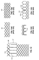
- one end of the device has continuous-strand apices 99 such as are shown in Fig. 13A.
- the strands on the opposite ends may be freely terminating ends 100, such as are shown in Fig. 13B; twisted together ends 101, such as are shown in Fig. 13C and in publication WO 99/25271; or atraumatically disposed ends in a non-braided architecture, such as for example in positions 102 and 103 as shown in Fig. 12 and further discussed in U.S. Patent 6,585,758 (Application Serial Number 09/442,165).
- These are only examples, however, as the free ends may terminate in any way known in the art.
- any free ends are typically secured by cutting the strands and melting them together to prevent fraying.
- a laser such as a CO 2 laser, is used to simultaneously cut and melt the fibers cleanly while the graft is mounted on a mandrel. Other methods may also be used.
- one end of a device may have some combination of continuous-strand apices 99 and otherwise-terminated free ends 100, 101, or 102 and 103
- a preferred stent embodiment comprises one end of stent having only continuous-strand apices 99.
- the braiding process proceeds from one end of the device to the other, typically either the body end comprises continuous-strand apices 99 and the leg ends comprise otherwise-terminated free ends 100, 101, or 102 and 103, or the leg ends comprise all continuous-strand apices and the body end comprises all otherwise-terminated free ends. All or only some of the leg ends may comprise continuous-strand apices.
- the above method for providing continuous-strand apices at one end may also be combined with the use of tapered filaments as described herein.
- a filament having multiple tapers with a relatively smaller diameter in a middle region of the wire and a relatively larger diameter in the opposite end regions may be wound onto two bobbins.
- the relatively smaller diameter filament may be, for example, wound about a protruding pin at the midpoint of the filament, and the each leg region braided as described herein.
- the trunk region may then be braided as described herein, with the taper in the filament diameter located such that the trunk has a relatively larger diameter filament than each of the legs.
- the filament may comprise only the first diameter at the opposite ends and the second diameter in the middle, with a gradual taper between regions, or the filament may comprise a third diameter intermediate the end and middle diameters for use in the bifurcated region.
- continuous-strand apices at one end may be further combined with the configurations described in U.S. Patent 6,610,087 (Application Serial Number 09/442,165), wherein one or more regions of the device may comprise a non-braided configuration.
- the midpoint of a strand such as a tapered filament, may be positioned at a non-braided end of a device, creating continuous apices 104 such as are shown in Fig. 13D.
- the non-braided architecture may be created, for example, by winding the strand about pins on a mandrel as is well known in the art, and then once the non-braided section has been formed, braiding the remainder of the stent about the mandrel as described herein.
- the parallel strand sections 105 in the non-braided portion may be optionally welded or otherwise joined together prior to braiding the remainder of the stent.
- a braided, non-bifurcated device may comprise tapered filaments wherein the ends of the device comprise larger cross-sectional area regions of the tapered filaments and the middle of the device comprises the smaller cross-sectional area regions of the tapered filaments.
- the smaller cross-sectional area regions may be on the ends and the larger cross-sectional area in the middle.
- the larger cross-sectional filament may be used in any region of the device desired to have increased stiffness and radial strength relative to the rest of the device, or may be used in certain regions to counteract influences which otherwise would result in lesser stiffness or lesser radial strength in such regions.
- Atraumatic end windings such as the continuous-strand apices described herein and with reference to Publication WO 99/25271 and the various configurations as described herein with reference to U.S. Patent 6,585,758 (Application Serial Number 09/442,165), may also be used in conjunction with tapered filaments in such braided, non-bifurcated devices. Such end windings may also be used in non-bifurcated devices without tapered filaments.
- the device is typically compressed into a radially compressed state into an introducer as is well-known in the art.
- the device is then introduced to the lumen into which it is to be deployed, navigated through the lumen to a deployment location, typically a diseased artery such as the aorta, and then expanded to a radially expanded state in the deployment location as is known in the art.
- a deployment location typically a diseased artery such as the aorta
- the deployment of a unitary device of the present invention is thus deployed by a method similar to that used for any unitary bifurcated device known in the art, and the deployment of a modular device according to the present invention is thus deployed by a method similar to that used for any modular bifurcated device known in the art.
- the method of the present invention may be used for creating a device that branches into any number of multiple lumen, so long as there are a sufficient number of bobbins available in the braiding machine to provide an adequate number of strands for braiding the branch sections.
- bobbins available in the braiding machine to provide an adequate number of strands for braiding the branch sections.
- machines with a greater number of bobbins may be designed without departing from the scope of this invention.
- Grafts made in accordance with this invention essentially resemble the stents depicted in the figures referred to herein, but typically with more strands so that there is little or no interstitial space between the braided strands.
- braided grafts traditionally require more strands than do stents
- the methods described herein with respect to circular braiding machines may be applied to grafts as well as stents.
- grafts typically comprise fabric yarns instead of wire filaments.
- the yarns used in this invention can vary over a wide range of linear density, depending on the devices used to fabricate the grafts and the application of the graft.
- the linear density should not be too low so as too become difficult to braid but should not be so high so that the profile of the formed graft is too great.
- the range of linear density may vary, using some braiding machines, over a range between 10 to 500 denier, preferably between about 40 to 225 denier.
- the thickness of the graft itself may vary over a wide range depending on the application and the desired profile.
- Typical thicknesses of the graft are between about 76 ⁇ m to about 381 ⁇ m (about 0.003 to about 0.015 inches), although not limited to such range.
- Such designs preferably comprise a large number of yarns (typically anywhere from about 75 to about 600, depending on yarn thickness, and preferably greater than about 200 yarns for thicknesses in a range of about 76 ⁇ m to about 381 ⁇ m (about 0.003 to about 0.015 inches)), however, the methods described herein requiring manual handling of multiple bobbins and carriers may be undesirably complex.
- one bifurcated braided graft may comprise 120 yarns for each leg portion and 240 yarns for the body portion.
- braiding methods and apparatus such as cartesian or jacquard braiding methods and machines, may be preferred, particularly for braiding grafts or composite stent-grafts that typically have a substantial number of yarns.
- Such methods may also be advantageous for braiding stents, particularly because they may allow the same design flexibility provided by using different circular braiding machines to make the legs versus the body, but without any of the complexity or extra steps required to move bobbins or bobbin carriers on and off the braiding equipment.
- Cartesian braiding methods and machines are known in the art for making tubular structures and such cartesian braiding methods and machines can be used in making a braided stent of the present invention.
- Cartesian braiding machines have the advantage of being able to move yarn carriers anywhere along an x-y plane, and may be controlled by computer software to maneuver the plurality of carriers as desired. This flexibility in maneuvering provides the ability to transition from the braiding of a single trunk section to the braiding of two leg sections without having to remove and replace particular yarn carriers on the machine. It also allows the two legs to be fabricated simultaneously, as opposed to the circular braiding method wherein the legs are fabricated sequentially.
- cartesian braiding apparatus allows easier interweaving of the yarns in the transition section between the trunk and leg sections, to minimize or eliminate any open crotch or open hip section.
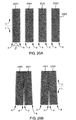
- FIG. 20A Yet another braiding method known in the art is flat braiding.
- Fig. 20A four flat braided strips 2000, 2001, 2002, and 2003 each having longitudinal sides A and B and upper and lower halves U and L. These braided strips may be created by any flat braiding method known in the art. The braiding may be performed in such a way as to leave loops 2005 on one or more of the longitudinal edges of the strips.
- upper halves U of strip 2000 side B and strip 2001 side A may be joined together, as may the upper halves U of strip 2002 side B and strip 2003 side A.
- the entire side B of strip 2001 may be joined to the entire side A of strip 2002.
- lower half L of strip 2002 side B may be joined to lower half L of strip 2001 side A and lower half L of strip 2003 side A may be joined to lower half L of strip 2000 side B, and the entire side B of strip 2003 joined to the entire side A of strip 2000 to form a bifurcated tubular structure, not shown.
- the above steps of joining the various portions of one strip to the other may be performed in any logical order desired.
- the longitudinal sides of the flat braided strips may be joined by any means known in the art, such as by threading graft yarns through the loops to stitch them together, or, for example, by positioning strip 2000 on one side of the flat braider and strip 2002 on the other side during the fabrication of strip 2001 so that upper side A of strip 2001 can be woven directly into upper side B of strip 2000 and the entire side B of strip 2001 can be woven directly into the entire side A of strip 2002.
- the strips may be made simultaneously with the appropriate sides or portions of sides being interwoven during fabrication of the strips.
- the other strips and sides may be so positioned so that the flat braiding step may be used to create the desired tubular structure.
- the strips may be joined along the desired sides by suturing, adhesive bonding, or any method known in the art.
- the bifurcated implantable device of this invention may comprise a composite stent-graft having structural stent filaments interbraided with fabric graft yarns.
- a composite stent-graft having structural stent filaments interbraided with fabric graft yarns.
- one may use between 5 and 30, preferably between 10 and 20 fabric yarns to obtain and interwoven stent-graft having increased rigidity over a braided graft.
- the bifurcated braided graft and bifurcated braided stent of the present invention may be separate elements that are joined together, such as with a polymer adhesive or with sutures.
- the resulting graft has a permeability of less than or equal to 1500 ml/cm 2 per minute.
- the braid angle ⁇ of the graft (shown in Fig. 20A) is approximately 110°.
Landscapes
- Engineering & Computer Science (AREA)
- Health & Medical Sciences (AREA)
- Biomedical Technology (AREA)
- Textile Engineering (AREA)
- Heart & Thoracic Surgery (AREA)
- Cardiology (AREA)
- Oral & Maxillofacial Surgery (AREA)
- Transplantation (AREA)
- Manufacturing & Machinery (AREA)
- Vascular Medicine (AREA)
- Life Sciences & Earth Sciences (AREA)
- Animal Behavior & Ethology (AREA)
- General Health & Medical Sciences (AREA)
- Public Health (AREA)
- Veterinary Medicine (AREA)
- Prostheses (AREA)
Claims (30)
- Sich verzweigende implantierbare Vorrichtung (50, 92, 2210, 2220) für die Entfaltung in einem Lumen, wobei die Vorrichtung (50, 92, 2210, 2220) einen Körper (52) umfasst, der sich in eine Vielzahl von Schenkeln (54, 56) verzweigt, wobei mindestens ein erster Schenkelabschnitt jedes Schenkels eine diskrete Vielzahl von kontinuierlichen Strängen (58L, 58R) umfasst, die zusammengeflochten sind, und mindestens ein erster Körperabschnitt des Körpers mindestens einen der kontinuierlichen Stränge (58) von jeder diskreten Vielzahl von kontinuierlichen Strängen (58L, 58R) umfasst, die zusammengeflochten sind, wobei die Vorrichtung (50, 92, 2210, 2220) ein Implantat (2220) umfasst, in dem die kontinuierlichen Stränge (58L, 58R) Gewebegame sind.
- Vorrichtung (50, 92, 2210, 2220) nach Anspruch 1, wobei die Vorrichtung (50, 92, 2210, 2220) des weiteren einen Stent (50, 92, 2210) zur Bildung eines Verbund-Stent-Implantats umfasst, bei dem die Vielzahl der Gewebegame mit einer Vielzahl von strukturellen Stentfilamenten (58) miteinander verflochten ist.
- Vorrichtung (2220) nach Anspruch 1 oder 2, wobei die Gewebegarne ein Material umfassen, das ausgewählt ist aus der Gruppe, bestehend aus Polyethylenterephthalat (PET), Polyetheretherketon (PEEK), Polysulfon, Polytetrafluorethylen (PTFE), aufgeschäumtem Polytetrafluorethylen (ePTFE), fluoriertem Ethylenpropylen (FEP), Polycarbonaturethan, einem Polyolefin, Silicon, Polyurethan und einer Kombination davon.
- Vorrichtung (2220) nach Anspruch 1 oder 2, wobei das Gewebegarn ein Polyolefin ist, ausgewählt aus der Gruppe, bestehend aus Polypropylen, Polyethylen, Niederdruckpolyethylen (HDPE) und einer Kombination davon.
- Vorrichtung (2220) nach den Ansprüchen 1 bis 4, die eine Anzahl von Garnen im Bereich von etwa 70 bis etwa 600 Garnen umfasst.
- Vorrichtung (2220) nach den Ansprüchen 1 bis 5, wobei die Gewebegame eine lineare Dichte von etwa 10 bis 500 Denier aufweisen.
- Vorrichtung (2220) nach Anspruch 6, wobei die Gewebegarne eine lineare Dichte von etwa 40 bis 225 Denier aufweisen.
- Vorrichtung (2220) nach den Ansprüchen 1 bis 7, wobei das Implantat (2220) eine Dicke im Bereich von etwa 76 µm bis etwa 381 µm (etwa 0,003 bis etwa 0,015 Zoll) aufweist.
- Vorrichtung (2220) nach den Ansprüchen 1 bis 8, wobei das Implantat (2220) eine Durchlässigkeit von weniger als oder gleich 1500 ml/cm2 pro Minute aufweist.
- Vorrichtung (2220) nach den Ansprüchen 1 bis 9, wobei das Implantat (2220) einen Flechtwinkel von etwa 110° aufweist.
- Vorrichtung (2220) nach den Ansprüchen 1 bis 10, wobei das geflochtene Implantat (2220) sowohl einen geschlossenen Gabelungsabschnitt (93) als auch einen geschlossenen Hüftabschnitt aufweist.
- Vorrichtung (2220) nach den Ansprüchen 1 bis 10, wobei das geflochtene Implantat (2220) einen offenen Gabelungsabschnitt (93, 2110) oder einen offenen Hüftabschnitt (95) aufweist und des weiteren einen Patch (2120) zur Verschließung des offenen Abschnitts aufweist.
- Vorrichtung (2220) nach den Ansprüchen 1 bis 12, wobei das geflochtene Implantat (2220) mit einem Polymer beschichtet ist, um die Durchlässigkeit zu verringern.
- Vorrichtung (2220) nach Anspruch 1, des weiteren umfassend einen Stent (2210), über oder unter dem das Implantat (2220) angeordnet ist, um eine Kombination aus Stent und Implantat zu schaffen, wobei die Kombination aus Stent und Implantat des weiteren mindestens eine Implantatmembran (2220), die an einer Innenfläche des Implantats (2220) oder Stents (2210), einer Außenfläche des Stents (2210) oder Implantats (2220) oder einer Kombination davon angeordnet ist, umfasst.
- Vorrichtung (50, 92, 2210, 2220) nach Anspruch 1, umfassend einen Stent zur Bildung einer Kombination aus Stent und Implantat, umfassend:einen Stent (50, 92, 2210), umfassend einen Stentkörper (52), der sich in eine Vielzahl von Stentschenkeln (54, 56) verzweigt, wobei mindestens ein erster Stentschenkelabschnitt jedes Stentschenkels eine diskrete Vielzahl von kontinuierlichen Stentfilamenten (58L, 58R) umfasst, die zusammengeflochten sind, und mindestens ein erster Stentkörperabschnitt des Stentkörpers mindestens eines der kontinuierlichen Stentfilamente (58) von jeder diskreten Vielzahl von kontinuierlichen Stentfilamenten (58L, 58R), die zusammengeflochten sind, umfasst,wobei der Stent (50, 92, 2210) und das Implantat (2220) diskrete Komponenten sind, die zur Bildung einer Kombination aus Stent und Implantat miteinander verbunden sind.
- Vorrichtung (50, 92, 2210, 2220) nach Anspruch 15, wobei der Stent (50, 92, 2210) und das Implantat (2220) mit einem Klebemittel miteinander verbunden sind.
- Vorrichtung (50, 92, 2210, 2220) nach Anspruch 15, wobei der Stent (50, 92, 2210) und das Implantat (2220) mit einer Vielzahl von Nähten miteinander verbunden sind.
- Verfahren zur Herstellung einer geflochtenen, verzweigten implantierbaren Vorrichtung (50, 92, 2210, 2220) mit einem Körper (52) und einer Vielzahl von Schenkeln (54, 56), wobei jeder Schenkel eine diskrete Vielzahl von Strängen (58L, 58R) umfasst, wobei das Verfahren die folgenden Schritte umfasst:(a) Flechten einer ersten Vielzahl von kontinuierlichen Strängen (58), um mindestens einen Abschnitt eines ersten Schenkels (54) einzeln zu bilden;(b) Flechten mindestens einer zweiten Vielzahl von kontinuierlichen Strängen (58), um mindestens einen Abschnitt eines zweiten Schenkels (56) einzeln zu bilden;(c) Zusammenflechten mindestens eines Strangs aus jedem der ersten Vielzahl von kontinuierlichen Strängen (58) und der zweiten Vielzahl von kontinuierlichen Strängen (58), um mindestens einen Abschnitt des Körpers (52) zu bilden;wobei die Vorrichtung ein Implantat umfasst und die Schritte (a) bis (c) unter Verwendung einer Vielzahl von Gewebegarnen durchgeführt werden.
- Verfahren nach Anspruch 18, das das Durchführen der Schritte (a) und (b) in der Reihenfolge vor dem Schritt (c) umfasst.
- Verfahren nach Anspruch 18, das das Durchführen des Schritts (c) in der Reihenfolge vor den Schritten (a) und (b) umfasst.
- Verfahren nach Anspruch 18, das das Durchführen der Schritte (a) bis (c) unter Verwendung einer kreisförmigen Flechtvorrichtung umfasst.
- Verfahren nach Anspruch 21, das das Durchführen des Schritts (a) und des Schritts (b) in der Reihenfolge umfasst.
- Verfahren nach Anspruch 18, das das Durchführen der Schritte (a) bis (c) unter Verwendung einer cartesischen Flechtvorrichtung umfasst.
- Verfahren nach Anspruch 23, das das gleichzeitige Durchführen des Schritts (a) und des Schritts (b) umfasst.
- Verfahren nach den Ansprüchen 18 bis 24, das das Durchführen von jedem der Schritte (a) bis (c) unter Verwendung einer Anzahl von Garnen in einem Bereich von etwa 70 bis etwa 600 umfasst.
- Verfahren nach den Ansprüchen 18 bis 25, wobei die Garne eine lineare Dichte im Bereich von etwa 10 bis 500 Denier aufweisen.
- Verfahren nach den Ansprüchen 18 bis 26, wobei die Garne eine lineare Dichte in einem Bereich von etwa 40 bis 225 Denier aufweisen.
- Verfahren nach Anspruch 18, das das Miteinanderverweben von einer Vielzahl von Gewebegarnen mit einer Vielzahl von strukturellen Stentfilamenten (58) umfasst, um eine einheitliche geflochtene, verzweigte Kombination aus Stent und Implantat zu schaffen.
- Vorrichtung (50, 92, 2210, 2220) nach Anspruch 2, wobei die strukturellen Stentfilamente (58) mit den Gewebegarnen in einem Verhältnis von 1 : 5 bis 1 : 30 verflochten werden.
- Vorrichtung (50, 92, 2210, 2220) nach Anspruch 2, wobei die strukturellen Stentfilamente (58) mit den Gewebegarnen in einem Verhältnis von 1 : 10 bis 1 : 20 verflochten werden.
Applications Claiming Priority (3)
| Application Number | Priority Date | Filing Date | Title |
|---|---|---|---|
| US702205 | 2000-10-31 | ||
| US09/702,205 US6652571B1 (en) | 2000-01-31 | 2000-10-31 | Braided, branched, implantable device and processes for manufacture thereof |
| PCT/US2001/030430 WO2002036046A2 (en) | 2000-10-31 | 2001-09-28 | Braided, branched, implantable device and processes for manufacture thereof |
Publications (2)
| Publication Number | Publication Date |
|---|---|
| EP1330211A2 EP1330211A2 (de) | 2003-07-30 |
| EP1330211B1 true EP1330211B1 (de) | 2007-02-07 |
Family
ID=24820252
Family Applications (1)
| Application Number | Title | Priority Date | Filing Date |
|---|---|---|---|
| EP01975552A Expired - Lifetime EP1330211B1 (de) | 2000-10-31 | 2001-09-28 | Geflochtene, verzweigte, implantierbare vorrichtung und verfahren zu deren herstellung |
Country Status (8)
| Country | Link |
|---|---|
| US (1) | US6652571B1 (de) |
| EP (1) | EP1330211B1 (de) |
| JP (1) | JP2004523256A (de) |
| AT (1) | ATE353201T1 (de) |
| AU (1) | AU2001294868A1 (de) |
| DE (1) | DE60126502T2 (de) |
| ES (1) | ES2281446T3 (de) |
| WO (1) | WO2002036046A2 (de) |
Cited By (2)
| Publication number | Priority date | Publication date | Assignee | Title |
|---|---|---|---|---|
| RU2465844C2 (ru) * | 2011-01-13 | 2012-11-10 | Сергей Владимирович Шалашов | Устройство для подтяжки лица и шеи |
| RU2616762C2 (ru) * | 2011-12-27 | 2017-04-18 | Уай. Джейкобс Медикал Инк. | Шовная нить для безузлового шва и набор, в состав которого входит эта шовная нить |
Families Citing this family (209)
| Publication number | Priority date | Publication date | Assignee | Title |
|---|---|---|---|---|
| US6006134A (en) | 1998-04-30 | 1999-12-21 | Medtronic, Inc. | Method and device for electronically controlling the beating of a heart using venous electrical stimulation of nerve fibers |
| US8579966B2 (en) | 1999-11-17 | 2013-11-12 | Medtronic Corevalve Llc | Prosthetic valve for transluminal delivery |
| US7018406B2 (en) | 1999-11-17 | 2006-03-28 | Corevalve Sa | Prosthetic valve for transluminal delivery |
| US8016877B2 (en) | 1999-11-17 | 2011-09-13 | Medtronic Corevalve Llc | Prosthetic valve for transluminal delivery |
| US8241274B2 (en) | 2000-01-19 | 2012-08-14 | Medtronic, Inc. | Method for guiding a medical device |
| US7749245B2 (en) | 2000-01-27 | 2010-07-06 | Medtronic, Inc. | Cardiac valve procedure methods and devices |
| US6622604B1 (en) | 2000-01-31 | 2003-09-23 | Scimed Life Systems, Inc. | Process for manufacturing a braided bifurcated stent |
| WO2002005888A1 (en) | 2000-06-30 | 2002-01-24 | Viacor Incorporated | Intravascular filter with debris entrapment mechanism |
| CA2419811A1 (en) | 2000-08-18 | 2002-02-28 | Atritech, Inc. | Expandable implant devices for filtering blood flow from atrial appendages |
| US8771302B2 (en) | 2001-06-29 | 2014-07-08 | Medtronic, Inc. | Method and apparatus for resecting and replacing an aortic valve |
| US8623077B2 (en) | 2001-06-29 | 2014-01-07 | Medtronic, Inc. | Apparatus for replacing a cardiac valve |
| US7544206B2 (en) | 2001-06-29 | 2009-06-09 | Medtronic, Inc. | Method and apparatus for resecting and replacing an aortic valve |
| FR2826863B1 (fr) | 2001-07-04 | 2003-09-26 | Jacques Seguin | Ensemble permettant la mise en place d'une valve prothetique dans un conduit corporel |
| FR2828091B1 (fr) | 2001-07-31 | 2003-11-21 | Seguin Jacques | Ensemble permettant la mise en place d'une valve prothetique dans un conduit corporel |
| US7097659B2 (en) | 2001-09-07 | 2006-08-29 | Medtronic, Inc. | Fixation band for affixing a prosthetic heart valve to tissue |
| US7147661B2 (en) | 2001-12-20 | 2006-12-12 | Boston Scientific Santa Rosa Corp. | Radially expandable stent |
| US9539121B2 (en) * | 2002-02-07 | 2017-01-10 | Dsm Ip Assets B.V. | Apparatus and methods for conduits and materials |
| US8721713B2 (en) | 2002-04-23 | 2014-05-13 | Medtronic, Inc. | System for implanting a replacement valve |
| US20040220654A1 (en) * | 2003-05-02 | 2004-11-04 | Cardiac Dimensions, Inc. | Device and method for modifying the shape of a body organ |
| US20040254628A1 (en) * | 2003-06-13 | 2004-12-16 | Patrice Nazzaro | One-branch stent-graft for bifurcated lumens |
| US11259945B2 (en) | 2003-09-03 | 2022-03-01 | Bolton Medical, Inc. | Dual capture device for stent graft delivery system and method for capturing a stent graft |
| US20080264102A1 (en) | 2004-02-23 | 2008-10-30 | Bolton Medical, Inc. | Sheath Capture Device for Stent Graft Delivery System and Method for Operating Same |
| US7763063B2 (en) | 2003-09-03 | 2010-07-27 | Bolton Medical, Inc. | Self-aligning stent graft delivery system, kit, and method |
| US8500792B2 (en) | 2003-09-03 | 2013-08-06 | Bolton Medical, Inc. | Dual capture device for stent graft delivery system and method for capturing a stent graft |
| US20070198078A1 (en) | 2003-09-03 | 2007-08-23 | Bolton Medical, Inc. | Delivery system and method for self-centering a Proximal end of a stent graft |
| US11596537B2 (en) | 2003-09-03 | 2023-03-07 | Bolton Medical, Inc. | Delivery system and method for self-centering a proximal end of a stent graft |
| US9198786B2 (en) | 2003-09-03 | 2015-12-01 | Bolton Medical, Inc. | Lumen repair device with capture structure |
| US8292943B2 (en) | 2003-09-03 | 2012-10-23 | Bolton Medical, Inc. | Stent graft with longitudinal support member |
| US9579194B2 (en) | 2003-10-06 | 2017-02-28 | Medtronic ATS Medical, Inc. | Anchoring structure with concave landing zone |
| US7186265B2 (en) | 2003-12-10 | 2007-03-06 | Medtronic, Inc. | Prosthetic cardiac valves and systems and methods for implanting thereof |
| US9526616B2 (en) | 2003-12-19 | 2016-12-27 | Cardiac Dimensions Pty. Ltd. | Mitral valve annuloplasty device with twisted anchor |
| US7824442B2 (en) | 2003-12-23 | 2010-11-02 | Sadra Medical, Inc. | Methods and apparatus for endovascularly replacing a heart valve |
| US11278398B2 (en) | 2003-12-23 | 2022-03-22 | Boston Scientific Scimed, Inc. | Methods and apparatus for endovascular heart valve replacement comprising tissue grasping elements |
| US8579962B2 (en) | 2003-12-23 | 2013-11-12 | Sadra Medical, Inc. | Methods and apparatus for performing valvuloplasty |
| US8343213B2 (en) | 2003-12-23 | 2013-01-01 | Sadra Medical, Inc. | Leaflet engagement elements and methods for use thereof |
| US20050137694A1 (en) | 2003-12-23 | 2005-06-23 | Haug Ulrich R. | Methods and apparatus for endovascularly replacing a patient's heart valve |
| US7329279B2 (en) | 2003-12-23 | 2008-02-12 | Sadra Medical, Inc. | Methods and apparatus for endovascularly replacing a patient's heart valve |
| US8182528B2 (en) | 2003-12-23 | 2012-05-22 | Sadra Medical, Inc. | Locking heart valve anchor |
| US9005273B2 (en) | 2003-12-23 | 2015-04-14 | Sadra Medical, Inc. | Assessing the location and performance of replacement heart valves |
| US7748389B2 (en) | 2003-12-23 | 2010-07-06 | Sadra Medical, Inc. | Leaflet engagement elements and methods for use thereof |
| US20050137687A1 (en) | 2003-12-23 | 2005-06-23 | Sadra Medical | Heart valve anchor and method |
| US8840663B2 (en) | 2003-12-23 | 2014-09-23 | Sadra Medical, Inc. | Repositionable heart valve method |
| US9526609B2 (en) | 2003-12-23 | 2016-12-27 | Boston Scientific Scimed, Inc. | Methods and apparatus for endovascularly replacing a patient's heart valve |
| US7445631B2 (en) | 2003-12-23 | 2008-11-04 | Sadra Medical, Inc. | Methods and apparatus for endovascularly replacing a patient's heart valve |
| US20120041550A1 (en) | 2003-12-23 | 2012-02-16 | Sadra Medical, Inc. | Methods and Apparatus for Endovascular Heart Valve Replacement Comprising Tissue Grasping Elements |
| US7959666B2 (en) | 2003-12-23 | 2011-06-14 | Sadra Medical, Inc. | Methods and apparatus for endovascularly replacing a heart valve |
| US7381219B2 (en) | 2003-12-23 | 2008-06-03 | Sadra Medical, Inc. | Low profile heart valve and delivery system |
| US7780725B2 (en) | 2004-06-16 | 2010-08-24 | Sadra Medical, Inc. | Everting heart valve |
| US8603160B2 (en) | 2003-12-23 | 2013-12-10 | Sadra Medical, Inc. | Method of using a retrievable heart valve anchor with a sheath |
| US8287584B2 (en) | 2005-11-14 | 2012-10-16 | Sadra Medical, Inc. | Medical implant deployment tool |
| EP2526899B1 (de) | 2003-12-23 | 2014-01-29 | Sadra Medical, Inc. | Umpositionierbare Herzklappe |
| US8828078B2 (en) | 2003-12-23 | 2014-09-09 | Sadra Medical, Inc. | Methods and apparatus for endovascular heart valve replacement comprising tissue grasping elements |
| US7824443B2 (en) | 2003-12-23 | 2010-11-02 | Sadra Medical, Inc. | Medical implant delivery and deployment tool |
| ITTO20040135A1 (it) | 2004-03-03 | 2004-06-03 | Sorin Biomedica Cardio Spa | Protesi valvolare cardiaca |
| EP1753374A4 (de) | 2004-04-23 | 2010-02-10 | 3F Therapeutics Inc | Implantierbares protheseventil |
| US20060052867A1 (en) | 2004-09-07 | 2006-03-09 | Medtronic, Inc | Replacement prosthetic heart valve, system and method of implant |
| US8562672B2 (en) | 2004-11-19 | 2013-10-22 | Medtronic, Inc. | Apparatus for treatment of cardiac valves and method of its manufacture |
| US7641681B2 (en) * | 2004-12-28 | 2010-01-05 | Boston Scientific Scimed, Inc. | Low profile stent-graft attachment |
| DE102005003632A1 (de) | 2005-01-20 | 2006-08-17 | Fraunhofer-Gesellschaft zur Förderung der angewandten Forschung e.V. | Katheter für die transvaskuläre Implantation von Herzklappenprothesen |
| AU2006206254B2 (en) | 2005-01-20 | 2012-02-09 | Cardiac Dimensions Pty. Ltd. | Tissue shaping device |
| ITTO20050074A1 (it) | 2005-02-10 | 2006-08-11 | Sorin Biomedica Cardio Srl | Protesi valvola cardiaca |
| US7962208B2 (en) | 2005-04-25 | 2011-06-14 | Cardiac Pacemakers, Inc. | Method and apparatus for pacing during revascularization |
| US20060247760A1 (en) * | 2005-04-29 | 2006-11-02 | Medtronic Vascular, Inc. | Methods and apparatus for treatment of aneurysms adjacent branch arteries |
| US7914569B2 (en) | 2005-05-13 | 2011-03-29 | Medtronics Corevalve Llc | Heart valve prosthesis and methods of manufacture and use |
| US7712606B2 (en) | 2005-09-13 | 2010-05-11 | Sadra Medical, Inc. | Two-part package for medical implant |
| US20070078510A1 (en) | 2005-09-26 | 2007-04-05 | Ryan Timothy R | Prosthetic cardiac and venous valves |
| US20070213813A1 (en) | 2005-12-22 | 2007-09-13 | Symetis Sa | Stent-valves for valve replacement and associated methods and systems for surgery |
| US9078781B2 (en) | 2006-01-11 | 2015-07-14 | Medtronic, Inc. | Sterile cover for compressible stents used in percutaneous device delivery systems |
| CN101415379B (zh) | 2006-02-14 | 2012-06-20 | 萨德拉医学公司 | 用于输送医疗植入物的系统 |
| US8075615B2 (en) | 2006-03-28 | 2011-12-13 | Medtronic, Inc. | Prosthetic cardiac valve formed from pericardium material and methods of making same |
| US7625403B2 (en) | 2006-04-04 | 2009-12-01 | Medtronic Vascular, Inc. | Valved conduit designed for subsequent catheter delivered valve therapy |
| US7524331B2 (en) | 2006-04-06 | 2009-04-28 | Medtronic Vascular, Inc. | Catheter delivered valve having a barrier to provide an enhanced seal |
| US7740655B2 (en) | 2006-04-06 | 2010-06-22 | Medtronic Vascular, Inc. | Reinforced surgical conduit for implantation of a stented valve therein |
| US7591848B2 (en) | 2006-04-06 | 2009-09-22 | Medtronic Vascular, Inc. | Riveted stent valve for percutaneous use |
| US11285005B2 (en) | 2006-07-17 | 2022-03-29 | Cardiac Dimensions Pty. Ltd. | Mitral valve annuloplasty device with twisted anchor |
| US11304800B2 (en) | 2006-09-19 | 2022-04-19 | Medtronic Ventor Technologies Ltd. | Sinus-engaging valve fixation member |
| US8876895B2 (en) | 2006-09-19 | 2014-11-04 | Medtronic Ventor Technologies Ltd. | Valve fixation member having engagement arms |
| US8834564B2 (en) | 2006-09-19 | 2014-09-16 | Medtronic, Inc. | Sinus-engaging valve fixation member |
| WO2008047354A2 (en) | 2006-10-16 | 2008-04-24 | Ventor Technologies Ltd. | Transapical delivery system with ventriculo-arterial overflow bypass |
| US8747459B2 (en) | 2006-12-06 | 2014-06-10 | Medtronic Corevalve Llc | System and method for transapical delivery of an annulus anchored self-expanding valve |
| US7871436B2 (en) | 2007-02-16 | 2011-01-18 | Medtronic, Inc. | Replacement prosthetic heart valves and methods of implantation |
| WO2008107885A2 (en) | 2007-03-05 | 2008-09-12 | Alon Shalev | Multi-component expandable supportive bifurcated endoluminal grafts and methods for using same |
| US7896915B2 (en) | 2007-04-13 | 2011-03-01 | Jenavalve Technology, Inc. | Medical device for treating a heart valve insufficiency |
| FR2915087B1 (fr) | 2007-04-20 | 2021-11-26 | Corevalve Inc | Implant de traitement d'une valve cardiaque, en particulier d'une valve mitrale, materiel inculant cet implant et materiel de mise en place de cet implant. |
| US8048147B2 (en) | 2007-06-27 | 2011-11-01 | Aga Medical Corporation | Branched stent/graft and method of fabrication |
| US8747458B2 (en) | 2007-08-20 | 2014-06-10 | Medtronic Ventor Technologies Ltd. | Stent loading tool and method for use thereof |
| US10856970B2 (en) | 2007-10-10 | 2020-12-08 | Medtronic Ventor Technologies Ltd. | Prosthetic heart valve for transfemoral delivery |
| US9848981B2 (en) | 2007-10-12 | 2017-12-26 | Mayo Foundation For Medical Education And Research | Expandable valve prosthesis with sealing mechanism |
| US20090171451A1 (en) * | 2007-12-27 | 2009-07-02 | Cook Incorporated | Implantable device having composite weave |
| EP3572045B1 (de) | 2008-01-24 | 2022-12-21 | Medtronic, Inc. | Stents für herzklappenprothesen |
| WO2009094501A1 (en) | 2008-01-24 | 2009-07-30 | Medtronic, Inc. | Markers for prosthetic heart valves |
| US9393115B2 (en) | 2008-01-24 | 2016-07-19 | Medtronic, Inc. | Delivery systems and methods of implantation for prosthetic heart valves |
| US8157853B2 (en) | 2008-01-24 | 2012-04-17 | Medtronic, Inc. | Delivery systems and methods of implantation for prosthetic heart valves |
| US9149358B2 (en) | 2008-01-24 | 2015-10-06 | Medtronic, Inc. | Delivery systems for prosthetic heart valves |
| US8628566B2 (en) | 2008-01-24 | 2014-01-14 | Medtronic, Inc. | Stents for prosthetic heart valves |
| WO2011104269A1 (en) | 2008-02-26 | 2011-09-01 | Jenavalve Technology Inc. | Stent for the positioning and anchoring of a valvular prosthesis in an implantation site in the heart of a patient |
| US9044318B2 (en) | 2008-02-26 | 2015-06-02 | Jenavalve Technology Gmbh | Stent for the positioning and anchoring of a valvular prosthesis |
| EP3005984B1 (de) | 2008-02-28 | 2025-10-01 | Medtronic Inc. | Herzklappenprothesensysteme |
| US8313525B2 (en) | 2008-03-18 | 2012-11-20 | Medtronic Ventor Technologies, Ltd. | Valve suturing and implantation procedures |
| US8430927B2 (en) | 2008-04-08 | 2013-04-30 | Medtronic, Inc. | Multiple orifice implantable heart valve and methods of implantation |
| US8312825B2 (en) | 2008-04-23 | 2012-11-20 | Medtronic, Inc. | Methods and apparatuses for assembly of a pericardial prosthetic heart valve |
| US8696743B2 (en) | 2008-04-23 | 2014-04-15 | Medtronic, Inc. | Tissue attachment devices and methods for prosthetic heart valves |
| ATE554731T1 (de) | 2008-05-16 | 2012-05-15 | Sorin Biomedica Cardio Srl | Atraumatische prothetische herzklappenprothese |
| CN102076281B (zh) | 2008-06-30 | 2014-11-05 | 波顿医疗公司 | 用于腹主动脉瘤的系统和方法 |
| EP4018967B1 (de) | 2008-09-15 | 2025-09-03 | Medtronic Ventor Technologies Ltd | Herzklappenprothese mit identifikationsvorrichtungen zur leichteren radiografischen positionierung |
| US8721714B2 (en) | 2008-09-17 | 2014-05-13 | Medtronic Corevalve Llc | Delivery system for deployment of medical devices |
| JP5607639B2 (ja) | 2008-10-10 | 2014-10-15 | サドラ メディカル インコーポレイテッド | 医療用デバイス・システム |
| US8137398B2 (en) | 2008-10-13 | 2012-03-20 | Medtronic Ventor Technologies Ltd | Prosthetic valve having tapered tip when compressed for delivery |
| US8986361B2 (en) | 2008-10-17 | 2015-03-24 | Medtronic Corevalve, Inc. | Delivery system for deployment of medical devices |
| ES2551694T3 (es) | 2008-12-23 | 2015-11-23 | Sorin Group Italia S.R.L. | Válvula protésica expansible dotada de apéndices de anclaje |
| US8151682B2 (en) | 2009-01-26 | 2012-04-10 | Boston Scientific Scimed, Inc. | Atraumatic stent and method and apparatus for making the same |
| CN106551740B (zh) | 2009-03-13 | 2020-03-27 | 波顿医疗公司 | 用于在手术部位部署腔内假体的系统和方法 |
| US9427302B2 (en) * | 2009-04-09 | 2016-08-30 | Medtronic Vascular, Inc. | Stent having a C-shaped body section for use in a bifurcation |
| EP2628465A1 (de) | 2009-04-27 | 2013-08-21 | Sorin Group Italia S.r.l. | Prothetische Gefässleitung |
| CA2961767C (en) | 2009-06-23 | 2018-08-14 | Endospan Ltd. | Vascular prostheses for treating aneurysms |
| US8808369B2 (en) | 2009-10-05 | 2014-08-19 | Mayo Foundation For Medical Education And Research | Minimally invasive aortic valve replacement |
| US9226826B2 (en) | 2010-02-24 | 2016-01-05 | Medtronic, Inc. | Transcatheter valve structure and methods for valve delivery |
| US8652204B2 (en) | 2010-04-01 | 2014-02-18 | Medtronic, Inc. | Transcatheter valve with torsion spring fixation and related systems and methods |
| US10856978B2 (en) | 2010-05-20 | 2020-12-08 | Jenavalve Technology, Inc. | Catheter system |
| IT1400327B1 (it) | 2010-05-21 | 2013-05-24 | Sorin Biomedica Cardio Srl | Dispositivo di supporto per protesi valvolari e corrispondente corredo. |
| CA2799459A1 (en) | 2010-05-25 | 2011-12-01 | Jenavalve Technology Inc. | Prosthetic heart valve and transcatheter delivered endoprosthesis comprising a prosthetic heart valve and a stent |
| BR112013004962A2 (pt) | 2010-09-01 | 2016-08-16 | Medtronic Vascular Galway Ltd | prótese, estrutura de suporte da válvula protética, e, método de colocação de uma prótese a um local desejado no corpo |
| AU2011300644B2 (en) | 2010-09-10 | 2015-08-20 | Symetis Sa | Valve replacement devices and a system comprising the valve replacement device and a delivery device therefor |
| KR101330825B1 (ko) * | 2011-01-14 | 2013-11-15 | 신경민 | 굽힘 특성이 양호한 스텐트의 제조방법과 그 스텐트 |
| US9526638B2 (en) | 2011-02-03 | 2016-12-27 | Endospan Ltd. | Implantable medical devices constructed of shape memory material |
| EP2486894B1 (de) | 2011-02-14 | 2021-06-09 | Sorin Group Italia S.r.l. | Vorrichtung zur nahtlosen Verankerung von Herzklappenprothesen |
| ES2641902T3 (es) | 2011-02-14 | 2017-11-14 | Sorin Group Italia S.R.L. | Dispositivo de anclaje sin sutura para prótesis valvulares cardiacas |
| WO2012127309A1 (en) | 2011-03-21 | 2012-09-27 | Ontorfano Matteo | Disk-based valve apparatus and method for the treatment of valve dysfunction |
| EP2520251A1 (de) | 2011-05-05 | 2012-11-07 | Symetis SA | Verfahren und Vorrichtung zum Zusammendrücken von Stentklappen |
| JP2014527425A (ja) | 2011-07-12 | 2014-10-16 | ボストン サイエンティフィック サイムド,インコーポレイテッドBoston Scientific Scimed,Inc. | 医療機器用の連結システム |
| US9839510B2 (en) | 2011-08-28 | 2017-12-12 | Endospan Ltd. | Stent-grafts with post-deployment variable radial displacement |
| WO2013065040A1 (en) | 2011-10-30 | 2013-05-10 | Endospan Ltd. | Triple-collar stent-graft |
| US9131926B2 (en) | 2011-11-10 | 2015-09-15 | Boston Scientific Scimed, Inc. | Direct connect flush system |
| US8940014B2 (en) | 2011-11-15 | 2015-01-27 | Boston Scientific Scimed, Inc. | Bond between components of a medical device |
| US8951243B2 (en) | 2011-12-03 | 2015-02-10 | Boston Scientific Scimed, Inc. | Medical device handle |
| US9597204B2 (en) | 2011-12-04 | 2017-03-21 | Endospan Ltd. | Branched stent-graft system |
| US9510945B2 (en) | 2011-12-20 | 2016-12-06 | Boston Scientific Scimed Inc. | Medical device handle |
| US9277993B2 (en) | 2011-12-20 | 2016-03-08 | Boston Scientific Scimed, Inc. | Medical device delivery systems |
| CN102551933A (zh) * | 2011-12-28 | 2012-07-11 | 微创医疗器械(上海)有限公司 | 编织支架 |
| EP2609893B1 (de) | 2011-12-29 | 2014-09-03 | Sorin Group Italia S.r.l. | Kit zur Implantation von prothetischen Gefäßleitungen |
| US10172708B2 (en) | 2012-01-25 | 2019-01-08 | Boston Scientific Scimed, Inc. | Valve assembly with a bioabsorbable gasket and a replaceable valve implant |
| EP3141223A1 (de) | 2012-04-12 | 2017-03-15 | Bolton Medical, Inc. | Vorrichtung zur abgabe einer gefässprothese |
| WO2013171730A1 (en) | 2012-05-15 | 2013-11-21 | Endospan Ltd. | Stent-graft with fixation elements that are radially confined for delivery |
| US9883941B2 (en) | 2012-06-19 | 2018-02-06 | Boston Scientific Scimed, Inc. | Replacement heart valve |
| KR101857033B1 (ko) | 2012-12-28 | 2018-05-14 | 현대자동차주식회사 | 브레이딩 공정을 이용한 주름형 프리폼 제조방법 및 이에 의하여 제조된 주름형 프리폼 |
| WO2014106850A1 (en) * | 2013-01-06 | 2014-07-10 | Shay Kahana | Connector |
| US9993360B2 (en) | 2013-01-08 | 2018-06-12 | Endospan Ltd. | Minimization of stent-graft migration during implantation |
| US9439751B2 (en) | 2013-03-15 | 2016-09-13 | Bolton Medical, Inc. | Hemostasis valve and delivery systems |
| WO2014179763A1 (en) | 2013-05-03 | 2014-11-06 | Medtronic Inc. | Valve delivery tool |
| US8870948B1 (en) | 2013-07-17 | 2014-10-28 | Cephea Valve Technologies, Inc. | System and method for cardiac valve repair and replacement |
| CN105491978A (zh) | 2013-08-30 | 2016-04-13 | 耶拿阀门科技股份有限公司 | 用于假体瓣膜的径向可折叠框架及其制造方法 |
| WO2015075708A1 (en) | 2013-11-19 | 2015-05-28 | Endospan Ltd. | Stent system with radial-expansion locking |
| US10231821B2 (en) * | 2014-05-08 | 2019-03-19 | The Secant Group, Llc | Composite lumen with reinforcing textile and matrix |
| US8956394B1 (en) | 2014-08-05 | 2015-02-17 | Woven Orthopedic Technologies, Llc | Woven retention devices, systems and methods |
| US9907593B2 (en) | 2014-08-05 | 2018-03-06 | Woven Orthopedic Technologies, Llc | Woven retention devices, systems and methods |
| US9943351B2 (en) | 2014-09-16 | 2018-04-17 | Woven Orthopedic Technologies, Llc | Woven retention devices, systems, packaging, and related methods |
| US9901445B2 (en) | 2014-11-21 | 2018-02-27 | Boston Scientific Scimed, Inc. | Valve locking mechanism |
| EP4306080A3 (de) | 2014-12-09 | 2024-04-10 | Cephea Valve Technologies, Inc. | Ersatzherzklappen und herstellungsverfahren |
| US20160168769A1 (en) * | 2014-12-12 | 2016-06-16 | Woven Orthopedic Technologies, Llc | Methods and systems for manufacturing woven retention devices |
| EP3068339B1 (de) | 2014-12-18 | 2017-11-01 | Endospan Ltd. | Endovaskuläre stentprothese mit einem ermüdungsbeständigen lateralrohr |
| WO2016115375A1 (en) | 2015-01-16 | 2016-07-21 | Boston Scientific Scimed, Inc. | Displacement based lock and release mechanism |
| US9861477B2 (en) | 2015-01-26 | 2018-01-09 | Boston Scientific Scimed Inc. | Prosthetic heart valve square leaflet-leaflet stitch |
| WO2016126524A1 (en) | 2015-02-03 | 2016-08-11 | Boston Scientific Scimed, Inc. | Prosthetic heart valve having tubular seal |
| US9788942B2 (en) | 2015-02-03 | 2017-10-17 | Boston Scientific Scimed Inc. | Prosthetic heart valve having tubular seal |
| US10285809B2 (en) | 2015-03-06 | 2019-05-14 | Boston Scientific Scimed Inc. | TAVI anchoring assist device |
| US10426617B2 (en) | 2015-03-06 | 2019-10-01 | Boston Scientific Scimed, Inc. | Low profile valve locking mechanism and commissure assembly |
| US10080652B2 (en) | 2015-03-13 | 2018-09-25 | Boston Scientific Scimed, Inc. | Prosthetic heart valve having an improved tubular seal |
| EP3270825B1 (de) | 2015-03-20 | 2020-04-22 | JenaValve Technology, Inc. | Herzklappenprothesenzuführsystem |
| EP3632378B1 (de) | 2015-05-01 | 2024-05-29 | JenaValve Technology, Inc. | Vorrichtung mit reduzierter herzschrittmacherrate bei herzklappenersatz |
| EP3294221B1 (de) | 2015-05-14 | 2024-03-06 | Cephea Valve Technologies, Inc. | Ersatz von mitralklappen |
| WO2016183523A1 (en) | 2015-05-14 | 2016-11-17 | Cephea Valve Technologies, Inc. | Cardiac valve delivery devices and systems |
| US10195392B2 (en) | 2015-07-02 | 2019-02-05 | Boston Scientific Scimed, Inc. | Clip-on catheter |
| US10335277B2 (en) | 2015-07-02 | 2019-07-02 | Boston Scientific Scimed Inc. | Adjustable nosecone |
| WO2017024277A1 (en) | 2015-08-05 | 2017-02-09 | Woven Orthopedic Technologies, Llc | Tapping devices, systems and methods for use in bone tissue |
| US10136991B2 (en) | 2015-08-12 | 2018-11-27 | Boston Scientific Scimed Inc. | Replacement heart valve implant |
| US10179041B2 (en) | 2015-08-12 | 2019-01-15 | Boston Scientific Scimed Icn. | Pinless release mechanism |
| US10779940B2 (en) | 2015-09-03 | 2020-09-22 | Boston Scientific Scimed, Inc. | Medical device handle |
| US10342660B2 (en) | 2016-02-02 | 2019-07-09 | Boston Scientific Inc. | Tensioned sheathing aids |
| US10583005B2 (en) | 2016-05-13 | 2020-03-10 | Boston Scientific Scimed, Inc. | Medical device handle |
| US10245136B2 (en) | 2016-05-13 | 2019-04-02 | Boston Scientific Scimed Inc. | Containment vessel with implant sheathing guide |
| US11065138B2 (en) | 2016-05-13 | 2021-07-20 | Jenavalve Technology, Inc. | Heart valve prosthesis delivery system and method for delivery of heart valve prosthesis with introducer sheath and loading system |
| US10201416B2 (en) | 2016-05-16 | 2019-02-12 | Boston Scientific Scimed, Inc. | Replacement heart valve implant with invertible leaflets |
| CN108463191B (zh) * | 2016-06-03 | 2020-03-20 | 浦易(上海)生物技术有限公司 | 一种鼻窦支架的编织成型方法和由此获得的支架 |
| EP3471665B1 (de) | 2016-06-17 | 2023-10-11 | Cephea Valve Technologies, Inc. | Vorrichtungen zur herzklappenfreisetzung |
| DE102016013486B3 (de) * | 2016-11-11 | 2018-01-04 | Admedes Schuessler Gmbh | Flechtmaschine und Weiche für eine Flechtmaschine |
| US11395681B2 (en) | 2016-12-09 | 2022-07-26 | Woven Orthopedic Technologies, Llc | Retention devices, lattices and related systems and methods |
| CA3051272C (en) | 2017-01-23 | 2023-08-22 | Cephea Valve Technologies, Inc. | Replacement mitral valves |
| AU2018203053B2 (en) | 2017-01-23 | 2020-03-05 | Cephea Valve Technologies, Inc. | Replacement mitral valves |
| CN110392557A (zh) | 2017-01-27 | 2019-10-29 | 耶拿阀门科技股份有限公司 | 心脏瓣膜模拟 |
| US10390953B2 (en) | 2017-03-08 | 2019-08-27 | Cardiac Dimensions Pty. Ltd. | Methods and devices for reducing paravalvular leakage |
| US10828154B2 (en) | 2017-06-08 | 2020-11-10 | Boston Scientific Scimed, Inc. | Heart valve implant commissure support structure |
| CN111163729B (zh) | 2017-08-01 | 2022-03-29 | 波士顿科学国际有限公司 | 医疗植入物锁定机构 |
| US10939996B2 (en) | 2017-08-16 | 2021-03-09 | Boston Scientific Scimed, Inc. | Replacement heart valve commissure assembly |
| US11246625B2 (en) | 2018-01-19 | 2022-02-15 | Boston Scientific Scimed, Inc. | Medical device delivery system with feedback loop |
| WO2019144069A2 (en) | 2018-01-19 | 2019-07-25 | Boston Scientific Scimed, Inc. | Inductance mode deployment sensors for transcatheter valve system |
| US11147668B2 (en) | 2018-02-07 | 2021-10-19 | Boston Scientific Scimed, Inc. | Medical device delivery system with alignment feature |
| WO2019165394A1 (en) | 2018-02-26 | 2019-08-29 | Boston Scientific Scimed, Inc. | Embedded radiopaque marker in adaptive seal |
| CN112399836B (zh) | 2018-05-15 | 2024-10-15 | 波士顿科学国际有限公司 | 置换心脏瓣膜连合组件 |
| US12318289B2 (en) | 2018-05-23 | 2025-06-03 | Corcym S.R.L. | Device for the in-situ delivery of heart valve prosthesis |
| WO2019224577A1 (en) | 2018-05-23 | 2019-11-28 | Sorin Group Italia S.R.L. | A cardiac valve prosthesis |
| US11241310B2 (en) | 2018-06-13 | 2022-02-08 | Boston Scientific Scimed, Inc. | Replacement heart valve delivery device |
| US11241312B2 (en) | 2018-12-10 | 2022-02-08 | Boston Scientific Scimed, Inc. | Medical device delivery system including a resistance member |
| US11439504B2 (en) | 2019-05-10 | 2022-09-13 | Boston Scientific Scimed, Inc. | Replacement heart valve with improved cusp washout and reduced loading |
| CN111118729B (zh) * | 2020-01-10 | 2021-06-01 | 江苏唯德康医疗科技有限公司 | 一种支架编织方法及使用该方法制成的支架 |
| WO2021262264A1 (en) | 2020-06-24 | 2021-12-30 | Bolton Medical, Inc. | Anti-backspin component for vascular prosthesis delivery device |
| EP4259045A4 (de) | 2020-12-14 | 2024-11-20 | Cardiac Dimensions Pty. Ltd. | Modulare vorbeladene medizinische implantate und abgabesysteme |
| WO2022217036A1 (en) | 2021-04-09 | 2022-10-13 | Boston Scientific Scimed, Inc. | Rotational alignment of medical implant |
| US20230255744A1 (en) * | 2022-02-17 | 2023-08-17 | Medtronic Vascular, Inc. | Endovascular stent graft having gate and implant joining liner |
| US12171658B2 (en) | 2022-11-09 | 2024-12-24 | Jenavalve Technology, Inc. | Catheter system for sequential deployment of an expandable implant |
Citations (1)
| Publication number | Priority date | Publication date | Assignee | Title |
|---|---|---|---|---|
| US6015433A (en) * | 1998-05-29 | 2000-01-18 | Micro Therapeutics, Inc. | Rolled stent with waveform perforation pattern |
Family Cites Families (34)
| Publication number | Priority date | Publication date | Assignee | Title |
|---|---|---|---|---|
| US2388693A (en) | 1944-04-29 | 1945-11-13 | Us Catheter & Instr Corp | Method and machine for making catheters |
| SE445884B (sv) | 1982-04-30 | 1986-07-28 | Medinvent Sa | Anordning for implantation av en rorformig protes |
| US4621560A (en) | 1985-04-11 | 1986-11-11 | Atlantic Research Corporation | Method of sequenced braider motion for multi-ply braiding apparatus |
| US4620473A (en) | 1985-08-19 | 1986-11-04 | Bull Jeffrey F | Mechanism for timing strand movement relative to rotation of spool holders or carriers for strand supply spools or bobbins |
| US4881444A (en) | 1988-06-24 | 1989-11-21 | Krauland Konrad L | Method and apparatus for braiding three-dimensional fabrics |
| US4885973A (en) | 1988-12-14 | 1989-12-12 | Airfoil Textron Inc. | Method of making composite articles |
| US4994071A (en) | 1989-05-22 | 1991-02-19 | Cordis Corporation | Bifurcating stent apparatus and method |
| US5360443A (en) | 1990-06-11 | 1994-11-01 | Barone Hector D | Aortic graft for repairing an abdominal aortic aneurysm |
| US5064435A (en) | 1990-06-28 | 1991-11-12 | Schneider (Usa) Inc. | Self-expanding prosthesis having stable axial length |
| US5398586A (en) | 1990-08-25 | 1995-03-21 | Murata Kikai Kabushiki Kaisha | Braided structure forming method |
| FR2678508B1 (fr) | 1991-07-04 | 1998-01-30 | Celsa Lg | Dispositif pour le renfort de vaisseaux du corps humain. |
| US5342387A (en) | 1992-06-18 | 1994-08-30 | American Biomed, Inc. | Artificial support for a blood vessel |
| GB9315910D0 (en) | 1993-07-31 | 1993-09-15 | Phillips Cables Ltd | Textile braids for cables,flexible tubes & the like |
| WO1995009586A1 (en) | 1993-10-01 | 1995-04-13 | Emory University | Self-expanding intraluminal composite prosthesis |
| US5609627A (en) | 1994-02-09 | 1997-03-11 | Boston Scientific Technology, Inc. | Method for delivering a bifurcated endoluminal prosthesis |
| BE1009278A3 (fr) | 1995-04-12 | 1997-01-07 | Corvita Europ | Tuteur auto-expansible pour dispositif medical a introduire dans une cavite d'un corps, et dispositif medical muni d'un tel tuteur. |
| US5758562A (en) | 1995-10-11 | 1998-06-02 | Schneider (Usa) Inc. | Process for manufacturing braided composite prosthesis |
| GB9522332D0 (en) | 1995-11-01 | 1996-01-03 | Biocompatibles Ltd | Braided stent |
| NZ331269A (en) | 1996-04-10 | 2000-01-28 | Advanced Cardiovascular System | Expandable stent, its structural strength varying along its length |
| US5718159A (en) | 1996-04-30 | 1998-02-17 | Schneider (Usa) Inc. | Process for manufacturing three-dimensional braided covered stent |
| US5800514A (en) * | 1996-05-24 | 1998-09-01 | Meadox Medicals, Inc. | Shaped woven tubular soft-tissue prostheses and methods of manufacturing |
| US5755778A (en) | 1996-10-16 | 1998-05-26 | Nitinol Medical Technologies, Inc. | Anastomosis device |
| AU5355598A (en) | 1996-11-07 | 1998-06-10 | Medtronic Instent, Inc. | Variable flexibility stent |
| AU5162598A (en) | 1996-11-07 | 1998-05-29 | Vascular Science Inc. | Tubular medical graft connectors |
| US5972017A (en) * | 1997-04-23 | 1999-10-26 | Vascular Science Inc. | Method of installing tubular medical graft connectors |
| US5957974A (en) | 1997-01-23 | 1999-09-28 | Schneider (Usa) Inc | Stent graft with braided polymeric sleeve |
| US5906641A (en) | 1997-05-27 | 1999-05-25 | Schneider (Usa) Inc | Bifurcated stent graft |
| FR2765097B1 (fr) | 1997-06-25 | 1999-08-06 | Braun Celsa Sa | Implant a resistance radiale a l'ecrasement variable, implantable dans un conduit anatomique |
| DE19750971A1 (de) | 1997-11-18 | 1999-07-08 | Schneider Europ Gmbh | Stent zur Implantation im menschlichen Körper, insbesondere in Blutgefäße |
| US6494907B1 (en) | 1998-04-28 | 2002-12-17 | Intratherapeutics, Inc. | Braided stent |
| US6156064A (en) * | 1998-08-14 | 2000-12-05 | Schneider (Usa) Inc | Stent-graft-membrane and method of making the same |
| US6159239A (en) * | 1998-08-14 | 2000-12-12 | Prodesco, Inc. | Woven stent/graft structure |
| ES2313882T3 (es) * | 1999-02-01 | 2009-03-16 | Board Of Regents, The University Of Texas System | Protesis endovasculares tejidas bifurcadas y trifurcadas y procedimiento para fabricar las mismas. |
| US6622604B1 (en) | 2000-01-31 | 2003-09-23 | Scimed Life Systems, Inc. | Process for manufacturing a braided bifurcated stent |
-
2000
- 2000-10-31 US US09/702,205 patent/US6652571B1/en not_active Expired - Fee Related
-
2001
- 2001-09-28 ES ES01975552T patent/ES2281446T3/es not_active Expired - Lifetime
- 2001-09-28 AU AU2001294868A patent/AU2001294868A1/en not_active Abandoned
- 2001-09-28 JP JP2002538858A patent/JP2004523256A/ja not_active Withdrawn
- 2001-09-28 DE DE60126502T patent/DE60126502T2/de not_active Expired - Lifetime
- 2001-09-28 AT AT01975552T patent/ATE353201T1/de not_active IP Right Cessation
- 2001-09-28 WO PCT/US2001/030430 patent/WO2002036046A2/en not_active Ceased
- 2001-09-28 EP EP01975552A patent/EP1330211B1/de not_active Expired - Lifetime
Patent Citations (1)
| Publication number | Priority date | Publication date | Assignee | Title |
|---|---|---|---|---|
| US6015433A (en) * | 1998-05-29 | 2000-01-18 | Micro Therapeutics, Inc. | Rolled stent with waveform perforation pattern |
Cited By (2)
| Publication number | Priority date | Publication date | Assignee | Title |
|---|---|---|---|---|
| RU2465844C2 (ru) * | 2011-01-13 | 2012-11-10 | Сергей Владимирович Шалашов | Устройство для подтяжки лица и шеи |
| RU2616762C2 (ru) * | 2011-12-27 | 2017-04-18 | Уай. Джейкобс Медикал Инк. | Шовная нить для безузлового шва и набор, в состав которого входит эта шовная нить |
Also Published As
| Publication number | Publication date |
|---|---|
| DE60126502D1 (de) | 2007-03-22 |
| US6652571B1 (en) | 2003-11-25 |
| WO2002036046A3 (en) | 2002-12-12 |
| ATE353201T1 (de) | 2007-02-15 |
| WO2002036046A2 (en) | 2002-05-10 |
| AU2001294868A1 (en) | 2002-05-15 |
| ES2281446T3 (es) | 2007-10-01 |
| WO2002036046A8 (en) | 2004-04-15 |
| EP1330211A2 (de) | 2003-07-30 |
| JP2004523256A (ja) | 2004-08-05 |
| DE60126502T2 (de) | 2007-11-15 |
Similar Documents
| Publication | Publication Date | Title |
|---|---|---|
| US6652571B1 (en) | Braided, branched, implantable device and processes for manufacture thereof | |
| EP1251799B1 (de) | Geflochtener, verzweigter stent und herstellungsverfahren | |
| US6942693B2 (en) | Braided branching stent, method for treating a lumen therewith, and process for manufacture thereof | |
| AU776127C (en) | Braided stent having tapered filaments | |
| EP1560544B1 (de) | Geflochtener stent und verfahren zu dessen herstellung | |
| EP0880949B1 (de) | Abzweigender Stent-Transplantat | |
| US20050288775A1 (en) | Metallic fibers reinforced textile prosthesis | |
| JPH10305050A (ja) | 編まれたポリマー製スリーブを有するステント移植片 |
Legal Events
| Date | Code | Title | Description |
|---|---|---|---|
| PUAI | Public reference made under article 153(3) epc to a published international application that has entered the european phase |
Free format text: ORIGINAL CODE: 0009012 |
|
| 17P | Request for examination filed |
Effective date: 20030520 |
|
| AK | Designated contracting states |
Designated state(s): AT BE CH CY DE DK ES FI FR GB GR IE IT LI LU MC NL PT SE TR |
|
| AX | Request for extension of the european patent |
Extension state: AL LT LV MK RO SI |
|
| 17Q | First examination report despatched |
Effective date: 20040920 |
|
| GRAP | Despatch of communication of intention to grant a patent |
Free format text: ORIGINAL CODE: EPIDOSNIGR1 |
|
| RIC1 | Information provided on ipc code assigned before grant |
Ipc: A61F 2/82 20060101AFI20060712BHEP |
|
| GRAS | Grant fee paid |
Free format text: ORIGINAL CODE: EPIDOSNIGR3 |
|
| GRAA | (expected) grant |
Free format text: ORIGINAL CODE: 0009210 |
|
| AK | Designated contracting states |
Kind code of ref document: B1 Designated state(s): AT BE CH CY DE DK ES FI FR GB GR IE IT LI LU MC NL PT SE TR |
|
| PG25 | Lapsed in a contracting state [announced via postgrant information from national office to epo] |
Ref country code: FI Free format text: LAPSE BECAUSE OF FAILURE TO SUBMIT A TRANSLATION OF THE DESCRIPTION OR TO PAY THE FEE WITHIN THE PRESCRIBED TIME-LIMIT Effective date: 20070207 Ref country code: AT Free format text: LAPSE BECAUSE OF FAILURE TO SUBMIT A TRANSLATION OF THE DESCRIPTION OR TO PAY THE FEE WITHIN THE PRESCRIBED TIME-LIMIT Effective date: 20070207 Ref country code: CH Free format text: LAPSE BECAUSE OF FAILURE TO SUBMIT A TRANSLATION OF THE DESCRIPTION OR TO PAY THE FEE WITHIN THE PRESCRIBED TIME-LIMIT Effective date: 20070207 Ref country code: DK Free format text: LAPSE BECAUSE OF FAILURE TO SUBMIT A TRANSLATION OF THE DESCRIPTION OR TO PAY THE FEE WITHIN THE PRESCRIBED TIME-LIMIT Effective date: 20070207 Ref country code: LI Free format text: LAPSE BECAUSE OF FAILURE TO SUBMIT A TRANSLATION OF THE DESCRIPTION OR TO PAY THE FEE WITHIN THE PRESCRIBED TIME-LIMIT Effective date: 20070207 |
|
| REG | Reference to a national code |
Ref country code: GB Ref legal event code: FG4D |
|
| REG | Reference to a national code |
Ref country code: CH Ref legal event code: EP |
|
| REG | Reference to a national code |
Ref country code: IE Ref legal event code: FG4D |
|
| REF | Corresponds to: |
Ref document number: 60126502 Country of ref document: DE Date of ref document: 20070322 Kind code of ref document: P |
|
| PG25 | Lapsed in a contracting state [announced via postgrant information from national office to epo] |
Ref country code: SE Free format text: LAPSE BECAUSE OF FAILURE TO SUBMIT A TRANSLATION OF THE DESCRIPTION OR TO PAY THE FEE WITHIN THE PRESCRIBED TIME-LIMIT Effective date: 20070507 |
|
| ET | Fr: translation filed | ||
| PG25 | Lapsed in a contracting state [announced via postgrant information from national office to epo] |
Ref country code: PT Free format text: LAPSE BECAUSE OF FAILURE TO SUBMIT A TRANSLATION OF THE DESCRIPTION OR TO PAY THE FEE WITHIN THE PRESCRIBED TIME-LIMIT Effective date: 20070709 |
|
| REG | Reference to a national code |
Ref country code: CH Ref legal event code: PL |
|
| REG | Reference to a national code |
Ref country code: ES Ref legal event code: FG2A Ref document number: 2281446 Country of ref document: ES Kind code of ref document: T3 |
|
| PLBE | No opposition filed within time limit |
Free format text: ORIGINAL CODE: 0009261 |
|
| STAA | Information on the status of an ep patent application or granted ep patent |
Free format text: STATUS: NO OPPOSITION FILED WITHIN TIME LIMIT |
|
| PGFP | Annual fee paid to national office [announced via postgrant information from national office to epo] |
Ref country code: BE Payment date: 20070417 Year of fee payment: 7 Ref country code: GB Payment date: 20070724 Year of fee payment: 7 |
|
| 26N | No opposition filed |
Effective date: 20071108 |
|
| PGFP | Annual fee paid to national office [announced via postgrant information from national office to epo] |
Ref country code: NL Payment date: 20070727 Year of fee payment: 7 |
|
| PG25 | Lapsed in a contracting state [announced via postgrant information from national office to epo] |
Ref country code: GR Free format text: LAPSE BECAUSE OF FAILURE TO SUBMIT A TRANSLATION OF THE DESCRIPTION OR TO PAY THE FEE WITHIN THE PRESCRIBED TIME-LIMIT Effective date: 20070508 Ref country code: MC Free format text: LAPSE BECAUSE OF NON-PAYMENT OF DUE FEES Effective date: 20070930 |
|
| BERE | Be: lapsed |
Owner name: BOSTON SCIENTIFIC LIMITED Effective date: 20080930 |
|
| GBPC | Gb: european patent ceased through non-payment of renewal fee |
Effective date: 20080928 |
|
| PG25 | Lapsed in a contracting state [announced via postgrant information from national office to epo] |
Ref country code: NL Free format text: LAPSE BECAUSE OF NON-PAYMENT OF DUE FEES Effective date: 20090401 |
|
| NLV4 | Nl: lapsed or anulled due to non-payment of the annual fee |
Effective date: 20090401 |
|
| PG25 | Lapsed in a contracting state [announced via postgrant information from national office to epo] |
Ref country code: CY Free format text: LAPSE BECAUSE OF FAILURE TO SUBMIT A TRANSLATION OF THE DESCRIPTION OR TO PAY THE FEE WITHIN THE PRESCRIBED TIME-LIMIT Effective date: 20070207 Ref country code: BE Free format text: LAPSE BECAUSE OF NON-PAYMENT OF DUE FEES Effective date: 20080930 |
|
| PG25 | Lapsed in a contracting state [announced via postgrant information from national office to epo] |
Ref country code: LU Free format text: LAPSE BECAUSE OF NON-PAYMENT OF DUE FEES Effective date: 20070928 |
|
| PG25 | Lapsed in a contracting state [announced via postgrant information from national office to epo] |
Ref country code: TR Free format text: LAPSE BECAUSE OF FAILURE TO SUBMIT A TRANSLATION OF THE DESCRIPTION OR TO PAY THE FEE WITHIN THE PRESCRIBED TIME-LIMIT Effective date: 20070207 |
|
| PG25 | Lapsed in a contracting state [announced via postgrant information from national office to epo] |
Ref country code: GB Free format text: LAPSE BECAUSE OF NON-PAYMENT OF DUE FEES Effective date: 20080928 |
|
| PGFP | Annual fee paid to national office [announced via postgrant information from national office to epo] |
Ref country code: ES Payment date: 20110905 Year of fee payment: 11 |
|
| PGFP | Annual fee paid to national office [announced via postgrant information from national office to epo] |
Ref country code: IT Payment date: 20110915 Year of fee payment: 11 |
|
| PGFP | Annual fee paid to national office [announced via postgrant information from national office to epo] |
Ref country code: IE Payment date: 20120912 Year of fee payment: 12 |
|
| PGFP | Annual fee paid to national office [announced via postgrant information from national office to epo] |
Ref country code: DE Payment date: 20120927 Year of fee payment: 12 Ref country code: FR Payment date: 20120926 Year of fee payment: 12 |
|
| PG25 | Lapsed in a contracting state [announced via postgrant information from national office to epo] |
Ref country code: IT Free format text: LAPSE BECAUSE OF NON-PAYMENT OF DUE FEES Effective date: 20120928 |
|
| REG | Reference to a national code |
Ref country code: ES Ref legal event code: FD2A Effective date: 20131018 |
|
| PG25 | Lapsed in a contracting state [announced via postgrant information from national office to epo] |
Ref country code: ES Free format text: LAPSE BECAUSE OF NON-PAYMENT OF DUE FEES Effective date: 20120929 |
|
| REG | Reference to a national code |
Ref country code: FR Ref legal event code: ST Effective date: 20140530 |
|
| REG | Reference to a national code |
Ref country code: IE Ref legal event code: MM4A |
|
| REG | Reference to a national code |
Ref country code: DE Ref legal event code: R119 Ref document number: 60126502 Country of ref document: DE Effective date: 20140401 |
|
| PG25 | Lapsed in a contracting state [announced via postgrant information from national office to epo] |
Ref country code: IE Free format text: LAPSE BECAUSE OF NON-PAYMENT OF DUE FEES Effective date: 20130928 |
|
| PG25 | Lapsed in a contracting state [announced via postgrant information from national office to epo] |
Ref country code: DE Free format text: LAPSE BECAUSE OF NON-PAYMENT OF DUE FEES Effective date: 20140401 Ref country code: FR Free format text: LAPSE BECAUSE OF NON-PAYMENT OF DUE FEES Effective date: 20130930 |