EP1330829B1 - Verfahren und vorrichtung zur erzeugung eines diskreten teilchens - Google Patents
Verfahren und vorrichtung zur erzeugung eines diskreten teilchens Download PDFInfo
- Publication number
- EP1330829B1 EP1330829B1 EP01981998A EP01981998A EP1330829B1 EP 1330829 B1 EP1330829 B1 EP 1330829B1 EP 01981998 A EP01981998 A EP 01981998A EP 01981998 A EP01981998 A EP 01981998A EP 1330829 B1 EP1330829 B1 EP 1330829B1
- Authority
- EP
- European Patent Office
- Prior art keywords
- particle
- droplet
- levitation device
- discrete
- plate
- Prior art date
- Legal status (The legal status is an assumption and is not a legal conclusion. Google has not performed a legal analysis and makes no representation as to the accuracy of the status listed.)
- Expired - Lifetime
Links
- 239000002245 particle Substances 0.000 title claims abstract description 202
- 238000000034 method Methods 0.000 title claims abstract description 65
- 238000005339 levitation Methods 0.000 claims abstract description 132
- 239000011159 matrix material Substances 0.000 claims abstract description 93
- 238000004949 mass spectrometry Methods 0.000 claims abstract description 30
- 230000006698 induction Effects 0.000 claims abstract description 27
- 238000004458 analytical method Methods 0.000 claims abstract description 23
- 238000003795 desorption Methods 0.000 claims abstract description 9
- 238000004807 desolvation Methods 0.000 claims abstract description 8
- 230000005520 electrodynamics Effects 0.000 claims description 98
- 150000002500 ions Chemical class 0.000 claims description 79
- 230000008021 deposition Effects 0.000 claims description 36
- 239000012491 analyte Substances 0.000 claims description 24
- 239000000463 material Substances 0.000 claims description 22
- 238000005070 sampling Methods 0.000 claims description 22
- 239000000758 substrate Substances 0.000 claims description 19
- 239000002904 solvent Substances 0.000 claims description 12
- 238000013519 translation Methods 0.000 claims description 10
- 239000000126 substance Substances 0.000 claims description 9
- 238000012360 testing method Methods 0.000 claims description 8
- 238000004891 communication Methods 0.000 claims description 7
- 238000001704 evaporation Methods 0.000 claims description 7
- 230000008020 evaporation Effects 0.000 claims description 6
- 230000001939 inductive effect Effects 0.000 claims description 6
- 238000004519 manufacturing process Methods 0.000 claims description 4
- 230000033001 locomotion Effects 0.000 abstract description 6
- 230000000694 effects Effects 0.000 abstract description 4
- 238000000132 electrospray ionisation Methods 0.000 abstract description 3
- 230000001627 detrimental effect Effects 0.000 abstract description 2
- 238000000816 matrix-assisted laser desorption--ionisation Methods 0.000 description 89
- PEDCQBHIVMGVHV-UHFFFAOYSA-N Glycerine Chemical compound OCC(O)CO PEDCQBHIVMGVHV-UHFFFAOYSA-N 0.000 description 42
- 238000000151 deposition Methods 0.000 description 41
- 239000000243 solution Substances 0.000 description 26
- 239000000523 sample Substances 0.000 description 25
- 238000001228 spectrum Methods 0.000 description 21
- OKKJLVBELUTLKV-UHFFFAOYSA-N Methanol Chemical compound OC OKKJLVBELUTLKV-UHFFFAOYSA-N 0.000 description 15
- 239000007789 gas Substances 0.000 description 15
- 238000000926 separation method Methods 0.000 description 15
- 239000010410 layer Substances 0.000 description 12
- 238000001819 mass spectrum Methods 0.000 description 12
- CSCPPACGZOOCGX-UHFFFAOYSA-N Acetone Chemical compound CC(C)=O CSCPPACGZOOCGX-UHFFFAOYSA-N 0.000 description 11
- 150000002148 esters Chemical class 0.000 description 10
- 230000004992 fission Effects 0.000 description 9
- 238000010304 firing Methods 0.000 description 8
- 239000007788 liquid Substances 0.000 description 8
- 102000004169 proteins and genes Human genes 0.000 description 8
- 108090000623 proteins and genes Proteins 0.000 description 8
- 229910001220 stainless steel Inorganic materials 0.000 description 8
- 239000010935 stainless steel Substances 0.000 description 8
- 239000012620 biological material Substances 0.000 description 7
- FAPWRFPIFSIZLT-UHFFFAOYSA-M Sodium chloride Chemical compound [Na+].[Cl-] FAPWRFPIFSIZLT-UHFFFAOYSA-M 0.000 description 6
- HEMHJVSKTPXQMS-UHFFFAOYSA-M Sodium hydroxide Chemical compound [OH-].[Na+] HEMHJVSKTPXQMS-UHFFFAOYSA-M 0.000 description 6
- 238000006243 chemical reaction Methods 0.000 description 6
- 238000001514 detection method Methods 0.000 description 6
- 230000005684 electric field Effects 0.000 description 6
- 239000007787 solid Substances 0.000 description 6
- IJGRMHOSHXDMSA-UHFFFAOYSA-N Atomic nitrogen Chemical compound N#N IJGRMHOSHXDMSA-UHFFFAOYSA-N 0.000 description 5
- 238000000429 assembly Methods 0.000 description 5
- 230000000712 assembly Effects 0.000 description 5
- 239000011248 coating agent Substances 0.000 description 5
- 238000000576 coating method Methods 0.000 description 5
- 230000001976 improved effect Effects 0.000 description 5
- 230000001965 increasing effect Effects 0.000 description 5
- 238000001840 matrix-assisted laser desorption--ionisation time-of-flight mass spectrometry Methods 0.000 description 5
- 230000035945 sensitivity Effects 0.000 description 5
- RYGMFSIKBFXOCR-UHFFFAOYSA-N Copper Chemical compound [Cu] RYGMFSIKBFXOCR-UHFFFAOYSA-N 0.000 description 4
- VVQNEPGJFQJSBK-UHFFFAOYSA-N Methyl methacrylate Chemical compound COC(=O)C(C)=C VVQNEPGJFQJSBK-UHFFFAOYSA-N 0.000 description 4
- 229920005372 Plexiglas® Polymers 0.000 description 4
- FKNQFGJONOIPTF-UHFFFAOYSA-N Sodium cation Chemical compound [Na+] FKNQFGJONOIPTF-UHFFFAOYSA-N 0.000 description 4
- 230000015572 biosynthetic process Effects 0.000 description 4
- 150000001768 cations Chemical class 0.000 description 4
- 239000000470 constituent Substances 0.000 description 4
- 229910052757 nitrogen Inorganic materials 0.000 description 4
- 229910001415 sodium ion Inorganic materials 0.000 description 4
- 239000007921 spray Substances 0.000 description 4
- 108010022337 Leucine Enkephalin Proteins 0.000 description 3
- 239000000443 aerosol Substances 0.000 description 3
- 238000013459 approach Methods 0.000 description 3
- 230000008901 benefit Effects 0.000 description 3
- 150000001875 compounds Chemical class 0.000 description 3
- 239000013078 crystal Substances 0.000 description 3
- 230000003111 delayed effect Effects 0.000 description 3
- 230000007062 hydrolysis Effects 0.000 description 3
- 238000006460 hydrolysis reaction Methods 0.000 description 3
- 230000000977 initiatory effect Effects 0.000 description 3
- URLZCHNOLZSCCA-UHFFFAOYSA-N leu-enkephalin Chemical compound C=1C=C(O)C=CC=1CC(N)C(=O)NCC(=O)NCC(=O)NC(C(=O)NC(CC(C)C)C(O)=O)CC1=CC=CC=C1 URLZCHNOLZSCCA-UHFFFAOYSA-N 0.000 description 3
- 238000005259 measurement Methods 0.000 description 3
- 238000002360 preparation method Methods 0.000 description 3
- 230000008569 process Effects 0.000 description 3
- 239000011780 sodium chloride Substances 0.000 description 3
- 238000000935 solvent evaporation Methods 0.000 description 3
- 229920004943 Delrin® Polymers 0.000 description 2
- DGAQECJNVWCQMB-PUAWFVPOSA-M Ilexoside XXIX Chemical compound C[C@@H]1CC[C@@]2(CC[C@@]3(C(=CC[C@H]4[C@]3(CC[C@@H]5[C@@]4(CC[C@@H](C5(C)C)OS(=O)(=O)[O-])C)C)[C@@H]2[C@]1(C)O)C)C(=O)O[C@H]6[C@@H]([C@H]([C@@H]([C@H](O6)CO)O)O)O.[Na+] DGAQECJNVWCQMB-PUAWFVPOSA-M 0.000 description 2
- 238000002679 ablation Methods 0.000 description 2
- 238000005513 bias potential Methods 0.000 description 2
- 239000003153 chemical reaction reagent Substances 0.000 description 2
- 230000003247 decreasing effect Effects 0.000 description 2
- 239000008367 deionised water Substances 0.000 description 2
- 230000001419 dependent effect Effects 0.000 description 2
- 239000010432 diamond Substances 0.000 description 2
- 238000006073 displacement reaction Methods 0.000 description 2
- 238000001035 drying Methods 0.000 description 2
- 239000012530 fluid Substances 0.000 description 2
- 239000011888 foil Substances 0.000 description 2
- 239000012634 fragment Substances 0.000 description 2
- 230000000379 polymerizing effect Effects 0.000 description 2
- 239000000376 reactant Substances 0.000 description 2
- 239000012488 sample solution Substances 0.000 description 2
- 229910052708 sodium Inorganic materials 0.000 description 2
- 239000011734 sodium Substances 0.000 description 2
- 125000006850 spacer group Chemical group 0.000 description 2
- 239000011550 stock solution Substances 0.000 description 2
- 239000012085 test solution Substances 0.000 description 2
- AFVLVVWMAFSXCK-UHFFFAOYSA-N α-cyano-4-hydroxycinnamic acid Chemical compound OC(=O)C(C#N)=CC1=CC=C(O)C=C1 AFVLVVWMAFSXCK-UHFFFAOYSA-N 0.000 description 2
- ROHFNLRQFUQHCH-YFKPBYRVSA-N L-leucine Chemical compound CC(C)C[C@H](N)C(O)=O ROHFNLRQFUQHCH-YFKPBYRVSA-N 0.000 description 1
- ROHFNLRQFUQHCH-UHFFFAOYSA-N Leucine Natural products CC(C)CC(N)C(O)=O ROHFNLRQFUQHCH-UHFFFAOYSA-N 0.000 description 1
- 102000018697 Membrane Proteins Human genes 0.000 description 1
- 108010052285 Membrane Proteins Proteins 0.000 description 1
- 102000007079 Peptide Fragments Human genes 0.000 description 1
- 108010033276 Peptide Fragments Proteins 0.000 description 1
- 238000001069 Raman spectroscopy Methods 0.000 description 1
- VYPSYNLAJGMNEJ-UHFFFAOYSA-N Silicium dioxide Chemical compound O=[Si]=O VYPSYNLAJGMNEJ-UHFFFAOYSA-N 0.000 description 1
- XUIMIQQOPSSXEZ-UHFFFAOYSA-N Silicon Chemical compound [Si] XUIMIQQOPSSXEZ-UHFFFAOYSA-N 0.000 description 1
- 238000007605 air drying Methods 0.000 description 1
- 229910001413 alkali metal ion Inorganic materials 0.000 description 1
- 230000004075 alteration Effects 0.000 description 1
- 230000005540 biological transmission Effects 0.000 description 1
- 239000005388 borosilicate glass Substances 0.000 description 1
- 230000003915 cell function Effects 0.000 description 1
- 238000012512 characterization method Methods 0.000 description 1
- 238000004587 chromatography analysis Methods 0.000 description 1
- 238000004581 coalescence Methods 0.000 description 1
- 238000002425 crystallisation Methods 0.000 description 1
- 230000008025 crystallization Effects 0.000 description 1
- 229910021641 deionized water Inorganic materials 0.000 description 1
- 238000013461 design Methods 0.000 description 1
- 238000011161 development Methods 0.000 description 1
- 238000009792 diffusion process Methods 0.000 description 1
- 102000038379 digestive enzymes Human genes 0.000 description 1
- 108091007734 digestive enzymes Proteins 0.000 description 1
- 229910001873 dinitrogen Inorganic materials 0.000 description 1
- 201000010099 disease Diseases 0.000 description 1
- 208000037265 diseases, disorders, signs and symptoms Diseases 0.000 description 1
- 229940079593 drug Drugs 0.000 description 1
- 239000003814 drug Substances 0.000 description 1
- 230000008029 eradication Effects 0.000 description 1
- 230000005284 excitation Effects 0.000 description 1
- 238000002474 experimental method Methods 0.000 description 1
- 238000004880 explosion Methods 0.000 description 1
- 238000001506 fluorescence spectroscopy Methods 0.000 description 1
- 230000006870 function Effects 0.000 description 1
- 239000005350 fused silica glass Substances 0.000 description 1
- 239000011521 glass Substances 0.000 description 1
- 230000005484 gravity Effects 0.000 description 1
- 238000005286 illumination Methods 0.000 description 1
- 230000006872 improvement Effects 0.000 description 1
- 238000003780 insertion Methods 0.000 description 1
- 230000037431 insertion Effects 0.000 description 1
- 150000002605 large molecules Chemical class 0.000 description 1
- 239000006193 liquid solution Substances 0.000 description 1
- 229920002521 macromolecule Polymers 0.000 description 1
- 238000013507 mapping Methods 0.000 description 1
- 230000000873 masking effect Effects 0.000 description 1
- 238000001254 matrix assisted laser desorption--ionisation time-of-flight mass spectrum Methods 0.000 description 1
- ZKHVKSAMEUAGEN-JSWGAMEVSA-N methyl (4r)-4-[(3r,5s,7r,8r,9s,10s,13r,14s,17r)-3,7-diacetyloxy-10,13-dimethyl-2,3,4,5,6,7,8,9,11,12,14,15,16,17-tetradecahydro-1h-cyclopenta[a]phenanthren-17-yl]pentanoate Chemical compound C([C@H]1C[C@H]2OC(C)=O)[C@H](OC(C)=O)CC[C@]1(C)[C@@H]1[C@@H]2[C@@H]2CC[C@H]([C@H](C)CCC(=O)OC)[C@@]2(C)CC1 ZKHVKSAMEUAGEN-JSWGAMEVSA-N 0.000 description 1
- 239000000203 mixture Substances 0.000 description 1
- 238000012986 modification Methods 0.000 description 1
- 230000004048 modification Effects 0.000 description 1
- 230000007935 neutral effect Effects 0.000 description 1
- 230000003287 optical effect Effects 0.000 description 1
- 230000010355 oscillation Effects 0.000 description 1
- 238000009428 plumbing Methods 0.000 description 1
- 108090000765 processed proteins & peptides Proteins 0.000 description 1
- 102000004196 processed proteins & peptides Human genes 0.000 description 1
- 238000005086 pumping Methods 0.000 description 1
- 230000009467 reduction Effects 0.000 description 1
- 230000008439 repair process Effects 0.000 description 1
- 238000011160 research Methods 0.000 description 1
- 238000012552 review Methods 0.000 description 1
- 102200097286 rs199472825 Human genes 0.000 description 1
- 238000007789 sealing Methods 0.000 description 1
- 239000010703 silicon Substances 0.000 description 1
- 229910052710 silicon Inorganic materials 0.000 description 1
- 150000003384 small molecules Chemical class 0.000 description 1
- 150000003385 sodium Chemical class 0.000 description 1
- 230000007480 spreading Effects 0.000 description 1
- 238000003892 spreading Methods 0.000 description 1
- 230000008093 supporting effect Effects 0.000 description 1
- 239000002344 surface layer Substances 0.000 description 1
- NHGXDBSUJJNIRV-UHFFFAOYSA-M tetrabutylammonium chloride Chemical class [Cl-].CCCC[N+](CCCC)(CCCC)CCCC NHGXDBSUJJNIRV-UHFFFAOYSA-M 0.000 description 1
- 238000005406 washing Methods 0.000 description 1
- XLYOFNOQVPJJNP-UHFFFAOYSA-N water Chemical compound O XLYOFNOQVPJJNP-UHFFFAOYSA-N 0.000 description 1
Images







Classifications
-
- H—ELECTRICITY
- H01—ELECTRIC ELEMENTS
- H01J—ELECTRIC DISCHARGE TUBES OR DISCHARGE LAMPS
- H01J49/00—Particle spectrometers or separator tubes
- H01J49/02—Details
- H01J49/04—Arrangements for introducing or extracting samples to be analysed, e.g. vacuum locks; Arrangements for external adjustment of electron- or ion-optical components
-
- H—ELECTRICITY
- H05—ELECTRIC TECHNIQUES NOT OTHERWISE PROVIDED FOR
- H05H—PLASMA TECHNIQUE; PRODUCTION OF ACCELERATED ELECTRICALLY-CHARGED PARTICLES OR OF NEUTRONS; PRODUCTION OR ACCELERATION OF NEUTRAL MOLECULAR OR ATOMIC BEAMS
- H05H3/00—Production or acceleration of neutral particle beams, e.g. molecular or atomic beams
- H05H3/04—Acceleration by electromagnetic wave pressure
-
- Y—GENERAL TAGGING OF NEW TECHNOLOGICAL DEVELOPMENTS; GENERAL TAGGING OF CROSS-SECTIONAL TECHNOLOGIES SPANNING OVER SEVERAL SECTIONS OF THE IPC; TECHNICAL SUBJECTS COVERED BY FORMER USPC CROSS-REFERENCE ART COLLECTIONS [XRACs] AND DIGESTS
- Y10—TECHNICAL SUBJECTS COVERED BY FORMER USPC
- Y10T—TECHNICAL SUBJECTS COVERED BY FORMER US CLASSIFICATION
- Y10T436/00—Chemistry: analytical and immunological testing
- Y10T436/24—Nuclear magnetic resonance, electron spin resonance or other spin effects or mass spectrometry
Definitions
- This invention pertains to the production of a discrete particle for application, for example, in the field of mass spectrometry.
- Mass spectrometry is a technique that weighs individual molecules, thus providing valuable chemical information.
- a mass spectrometer operates by exerting forces on charged particles (ions) in a vacuum using magnetic and electric fields.
- a compound must be charged (ionized) to be analyzed in a mass spectrometer.
- the ions must be introduced in the gas phase into the vacuum of the mass spectrometer. Ionizing large molecules of biological origins such as proteins, peptides and strands of DNA and RNA has proven difficult in the past since these molecules have effectively zero vapour pressure and are labile.
- a major thrust in mass spectrometry for some time has been the development of ionization sources for such large bio-molecules.
- Electrospray ionization ESI
- MALDI matrix-assisted laser desorption and ionization
- ESI is a desolvation method in which a high DC electric potential is applied to a metallic capillary needle that is separated from a counter electrode held at a lower DC potential.
- the electric field causes a liquid (containing the analyte in solution) emerging from the capillary to be dispersed into a fine spray of millions of charged droplets.
- the droplets in the aerosol carry a net charge of the same polarity as the electric field.
- the solvent evaporates from the droplets the droplets decrease in size, increasing the charge concentration on the droplet surface.
- a "Coulombic explosion” occurs when Coulombic repulsion overcomes a droplet's surface tension. This results in the droplet exploding, forming a series of smaller, lower charged droplets.
- This process of shrinking and exploding repeats until individually charged analyte ions are formed.
- the rate of solvent evaporation can be increased by introducing a drying gas flow counter to the current of the sprayed ions. Nitrogen is frequently used as the drying gas.
- the cyclical process of coulomb fission and solvent evaporation ultimately leads to the deposition of net charge onto the analyte molecule (e.g. bio-molecule) in the droplet.
- the bio-molecule adducted by, for example, multiple protons, is desorbed from the droplet at atmospheric pressure. A small fraction of these ions pass through an orifice into the vacuum of the mass spectrometer for analysis.
- a disadvantage of the ESI method is that only a small fraction (0.01 % or less) of the sample material is utilized.
- the majority of the material emerging from the capillary ends up on the counter electrode or on the plate that has the sampling orifice.
- the reason for this is that the electric field that disperses the liquid solution into droplets is also responsible for causing detrimental space charge effects. Space charge effects arise because each droplet, and the resulting ions in the aerosol plume, all carry net charge of the same polarity, causing these droplets/ions to repel one another because of electrostatic repulsion. This causes the spray of droplets leaving the tip of the capillary to spread out into a cone having its apex at the tip of the capillary.
- MALDI involves the deposition of a sample, usually as a liquid, onto a flat plate or into recessed wells formed in a plate.
- a matrix of one or more compounds is also used.
- the matrix may be a solid or a liquid.
- the sample material can be deposited as a layer on top of or below the matrix or intimately mixed with the matrix.
- the matrix molecules are present in the starting solution in a concentration approximately 1000 times greater than the analyte molecules.
- the plate is exposed to a pulsed laser beam.
- the matrix absorbs the energy from the laser, causing rapid vibrational excitation and desorption of the chromophore.
- the matrix molecules evaporate away and the desorbed analyte molecules can be cationized by a proton or an alkali metal ion.
- the ionized analyte molecules can be analyzed using a time-of-flight ("TOF") analyzer.
- TOF time-of-flight
- the overall technique is often referred to as matrix-assisted laser desorption and ionization time-of-flight mass spectrometry ("MALDI-TOF-MS").
- the need has therefore arisen for a method and apparatus for producing a source of ions, suitable for mass spectrometric analysis, from a discrete particle.
- the need has also arisen for improved techniques for depositing an analyte, such as a bio-molecule, onto a plate for MALDI mass spectrometry.
- the invention is an apparatus as set forth in claim 1 and the corresponding method as set forth in claim 39.
- the apparatus comprises a particle generator for generating a discrete particle; an induction electrode for inducing a net charge onto the discrete particle; and a levitation device for electrodynamically levitating the discrete particle following the induction of the net charge.
- the levitation device is an electrodynamic balance comprising a pair of separated levitation electrodes.
- the levitation electrodes may include a pair of first ring electrodes extending in parallel planes.
- a voltage difference is maintained across the first ring electrodes.
- the voltage across the first ring electrodes may be approximately 20 V.
- the electrodynamic balance may be operable at variable frequencies.
- the levitation device may be substantially enclosed within a chamber.
- the apparatus may also include an electrode assembly for delivering the discrete particle from the levitation device to a target remote from the levitation device.
- the remote target may be, for example, an orifice in communication with the vacuum chamber of an atmospheric gas sampling mass spectrometer.
- the remote target may be a substrate for deposition of the particle thereon, such as a plate suitable for matrix assisted laser desorption and ionization mass spectrometric analysis.
- the electrode assembly may form part of the levitation device or it may constitute a separate component of the apparatus.
- the electrode assembly is operable at atmospheric pressure and comprises a first plate electrode positioned between the particle generator and the levitation device and a second plate electrode positioned between the levitation device and the orifice.
- the levitation device is located proximal to the orifice and includes the electrode assembly.
- the electrode assembly may comprise a quadrupole electrode assembly disposed between the levitation device and the orifice.
- the various electrode assemblies described herein may also be used if the remote target is something other than the an orifice in communication with a vacuum chamber of a mass spectrometer, such as a MALDI plate or some other substrate suitable for deposition of the discrete particle thereon.
- the discrete particle may be deposited on a plate suitable for matrix assisted laser desorption and ionization mass spectrometric analysis.
- the plate preferably comprises a material for receiving the particle, such as a matrix coated on the plate.
- the particle generated by the particle generator may also comprise matrix material which is deposited on to the plate during the deposition step.
- the plate may comprise at least one recessed well. Each well may be pre-loaded with test samples, such as biological or chemical material potentially reactive with the discrete particle(s) deposited on to the plate.
- the Applicant's apparatus may also include a translation stage for supporting a substrate, such as a MALDI plate.
- the translation stage is controllably movable relative to the levitation device.
- the apparatus may comprise a particle generator for generating a discrete particle and a levitation device for levitating the discrete particle, wherein the discrete particle is delivered by the apparatus to a target remote from the levitation device.
- An electrode assembly may be employed for delivering the particle from the levitation device to the remote target as discussed above.
- a laser having an adjustable focal point may be employed. In this embodiment the particle is delivered from the levitation device to the target by the laser.
- an apparatus for delivering a source of ions to a vacuum chamber of a mass spectrometer includes a droplet generator for generating a single isolated droplet, the droplet comprising solvent; an induction electrode for applying a net charge onto the droplet; a levitation device for levitating the droplet for a period of time sufficient to permit desolvation of the droplet to cause the droplet to become unstable, thereby releasing ions by droplet Coulomb fission; an orifice in communication with the vacuum chamber; and an electrode assembly for delivering the ions from the levitation device to the orifice.
- the Applicant's invention also includes in an embodiment a mass spectrometer comprising a vacuum chamber; a detector for detecting the passage of ions through the vacuum chamber; a particle generator for generating a discrete particle; an induction electrode for ionizing the particle; a levitation device for electrodynamically levitating the discrete particle following the ionization; an orifice in communication with the vacuum chamber; and means to deliver the ionized particle from the levitation device to the orifice.
- a mass spectrometer comprising a vacuum chamber; a detector for detecting the passage of ions through the vacuum chamber; a particle generator for generating a discrete particle; an induction electrode for ionizing the particle; a levitation device for electrodynamically levitating the discrete particle following the ionization; an orifice in communication with the vacuum chamber; and means to deliver the ionized particle from the levitation device to the orifice.
- a method for producing a discrete particle for subsequent analysis or manipulation comprises (a) generating a discrete particle; (b) inducing a net charge onto the discrete particle; (c) and electrodynamically levitating the discrete particle following the induction of the net charge.
- step (c) is carried out at atmospheric pressure.
- the method may also include the step of delivering the discrete particle from the levitation device to a target remote from the levitation device.
- the discrete particle may be delivered to an atmospheric gas sampling mass spectrometer or a remote substrate, such as a MALDI plate.
- a material, such as a matrix may be applied to the plate for receiving the particle.
- the particle itself may also comprise matrix material.
- the method may also include the step of moving the substrate relative to the levitation device, such as during a particle deposition session.
- the net charge is preferably induced when the particle is generated.
- the particle may be levitated by applying a constant voltage difference across an electrodynamic balance.
- the discrete particle may be subjected to a gas while it is levitated to control the evaporation rate of the solvent.
- a method for separating a particle into sub-particles for subsequent analysis comprises (a) generating a discrete particle comprising sub-particles; (b) inducing a net charge onto the particle; (c) electrodynamically levitating the particle (d) separating the sub-particles from the particle; and (e) sequentially delivering the sub-particles to a target for subsequent analysis.
- Applicant's method includes the steps of (a) generating a discrete particle; (b) levitating the discrete particle; and (c) delivering the discrete particle to the target.
- step (c) may be carried out by capturing the discrete particle in a laser beam and adjusting the focal point of the laser.
- the discrete particle may be levitated electrodynamically.
- a method of mass spectrometry comprising: (a) generating a discrete particle; (b) ionizing the discrete particle; (c) electrodynamically levitating the ionized discrete particle; (d) delivering the ionized discrete particle to a vacuum chamber of an atmospheric pressure gas sampling mass spectrometer; and (e) detecting the passage of the ionized discrete particle through the vacuum chamber.
- a method for carrying out a reaction comprising: (a) generating a plurality of discrete particles; (b) levitating the plurality of discrete particles; and (c) manipulating the plurality of discrete particles to react with one another while the plurality of discrete particles are levitating.
- FIG. 1 is a schematic drawing depicting a prior art ESI arrangement.
- ESI arrangement 10 a metallic capillary 12 having an applied DC voltage is separated from a counter electrode 14 held at a lower DC potential.
- a plate 16 is positioned behind the counter electrode 14 and has an orifice 18 therein to allow the passage of ionized analyte molecules.
- To the right of sampling orifice 18 are the first and second stages of a differential vacuum.
- the region between plate 16 and a skimmer 19 is held at a first pressure and the pressure in the main vacuum chamber to the right of skimmer 19 is held at a lower pressure.
- the ionized molecules pass through a mass-to-charge analyzer 20 and are detected by a detector 22.
- ESI arrangement 10 the liquid emerging from capillary 12 is dispersed into a fine spray 24 of droplets 26.
- the cyclical process of Coloumb fission and solvent evaporation ultimately leads to the deposition of a net charge onto the analyte molecules in the droplets.
- much of the sample is wasted with ESI arrangement 10 because the droplets 26, all having net charge of the same polarity, repel, resulting in the spray 24 spreading out over an area that is many times greater than the aperture 28 in the counter electrode 14 and the orifice 18 leading into the vacuum.
- the overall sample utilization efficiency is low in conventional ESI arrangement 10.
- this invention is based on the generation of a discrete particle.
- particle includes a solid member, a droplet, a single molecule or a cluster of molecules (including one or more cells). A particle may therefore include one or more sub-particles.
- the "particle” discussed herein is a single isolated droplet comprising an analyte (e.g. bio-molecule) and solvent. A net charge is placed onto the particle as it is generated.
- the term “ion” means a particle having a net charge.
- the discrete particle is delivered to a levitation device. Delivery of the discrete particle could be accomplished, for example, by the particle generator used to generate the discrete particle.
- the particle generator is a droplet generator
- the application of an electric pulse to a piezoelectric crystal in the droplet generator will eject an isolated droplet with sufficient velocity to travel to the levitation device.
- Other suitable means to deliver the particle to the levitation device such as gas stream, could alternatively be used.
- the discrete particle is electrodynamically levitated by a levitation device.
- levitated means that the particle is suspended.
- the period of time a particle is levitated may be varied depending upon the particular circumstances.
- the particle is then delivered from the levitation device to a remote target.
- the target is "remote" from the levitation device in the sense that it is spacially separated from the center or null position of the levitation device to some degree, although the quantum of separation may be small.
- the target is an orifice leading into (or otherwise in communication with) the vacuum of an atmospheric gas (and ion) sampling mass spectrometer.
- the target is a plate to be subjected to MALDI mass spectrometry following deposition of the particle on the plate.
- the discrete particle may be delivered to the target by an electrode assembly.
- the discrete particle is a droplet
- the net charge lost from the droplet (referred to as a "parent" droplet) by Coloumb fission is delivered to the orifice of the mass spectrometer by manipulating the smaller droplets (referred to as "progeny" droplets). It is possible to levitate one or more particles in the levitation device simultaneously.
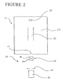
- FIG. 2 is a schematic illustration of an apparatus 29 of the invention.
- Apparatus 29 comprises a particle generator 32 and a levitation device 30.
- Particle generator 30 can be any means to generate a discrete particle, such as, for example, an aerosol generator or a droplet generator.
- Levitation device 30 can be any means to levitate a discrete particle.
- levitation device 30 has been described herein as comprising an electrodynamic balance comprised of two ring electrodes 48, 50.
- ring electrodes 48, 50 may have different geometric configurations (e.g. annular and non-annular) without departing from the invention.
- a discrete particle (not shown) is generated by particle generator 32, delivered to levitation device 30 and then levitated by levitation device 30 between ring electrodes 48, 50.
- an induction electrode 52 Positioned between droplet generator 32 and levitation device 30 is an induction electrode 52.
- An electric potential is applied to induction electrode so as to induce a net charge of a desired polarity onto the discrete particle generated by particle generator 32.
- a positive DC potential can be applied to induction electrode 52 to induce a negative net charge onto a discrete particle generated by particle generator 32.
- a negative DC potential could be applied to induction electrode if it is desired to induce a net positive charge onto the discrete particle.
- Figure 2 also illustrates an atmospheric gas (and ion) sampling mass spectrometer 31 having an orifice 33, a mass filter 35 in a vacuum chamber 37 and a detector 39. Following levitation of the particle in electrodynamic balance 30, it is delivered to the orifice 33 for analysis by mass spectrometer 31.
- the discrete particle may be delivered from the electrodynamic balance 30 and deposited onto a plate that is to be subjected to MALDI mass spectrometry analysis.
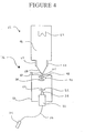
- Figures 3-6 and 10 are schematic drawings of further exemplary apparatuses 68, 76, 78, 81, 88 of the invention in which the particle generator 32 is a droplet generator and the levitation device 30 is an electrodynamic balance comprised of ring electrodes 48, 50.
- the apparatuses 68, 76, 78, 81, 88 each comprise a levitation device 30 and a droplet generator 32.
- Droplet generator 32 is operatively connected to a liquid sample containing the analyte in solution. As illustrated in Figures 3-6 and 10 , the droplet generator 32 may be connected at a bottom portion 32b to a syringe 34 by tubing 36. It will be appreciated that liquid sample delivery could also be made by any one of other known methods, for example, a separation method such as a chromatography column or a micro-fabricated column on a glass or silicon chip.
- a nozzle 38 is fitted to an upper portion 32a of the droplet generator 32 in the embodiments illustrated in Figures 3-6 .
- Nozzle 38 assists in maintaining stable droplet generation.
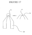
- Nozzle 38 is illustrated in more detail in Figure 17 .
- Nozzle 38 has a flat tip 40 surrounding an aperture 42.
- Aperture 42 is vertically coaxial with the center of the levitation device 30 and the orifice 44 leading to the vacuum chamber 46.
- Levitation device 30 is positioned above droplet generator 32.
- levitation device 30 is an electrodynamic balance comprised of two parallel vertically spaced-apart ring electrodes 48, 50. Ring electrodes 48, 50 may be constructed of copper wire. Ring electrodes 48, 50 are also depicted in Figure 8 .
- induction electrode 52 Positioned between droplet generator 32 and electrodynamic balance 30 is an induction electrode 52. A potential is applied to induction electrode 52 so that a net charge is induced onto each droplet generated from droplet generator 32 before it is delivered to the electrodynamic balance 30. The polarity of the potential will be determined by the net charge desired to be induced onto the droplet generated by droplet generator 32.
- mass spectrometer 65 comprises a vacuum chamber 46, a skimmer 58 having an orifice 57 in alignment with droplet generator 52, and a delrin spacer 62 electrically isolating the skimmer 58 from the vacuum chamber 46.
- the vacuum chamber 46 houses a channel electron multiplier 64, which passes the CEM ion current to an appropriate counting unit (not shown).
- the vacuum chamber 46 may be differentially pumped.
- the apparatuses 68, 76, 78, 81 of Figures 3-6 also comprise a plexiglass chamber 66 enclosing the electrodynamic balance 30 in order to minimize convection currents that might otherwise preclude levitation of the droplet(s).
- An orifice 44 in a top plate 67 leads into the vacuum chamber 46 of mass spectrometer 65.
- the apparatuses 68, 76, 78, 81 illustrated in Figures 3-6 are identical with respect to: (a) the structure of electrodynamic balance 30 and droplet generator 32; and (b) the separation between nozzle 38 of droplet generator 32 and electrodynamic balance 30.
- the structural differences between the apparatuses 68, 76, 78, 81 relate to the arrangement of various electrode assemblies for the manipulation and direction of progeny droplets and ions from the electrodynamic balance 30 toward the orifice 44 leading into vacuum chamber 46 of a mass spectrometer 65.
- apparatus 68 comprises a two electrode assembly to guide progeny droplets and the ions desorbed from such droplets toward the sampling orifice 44.
- the two electrode assembly comprises a bottom electrode and a top electrode.
- Bottom electrode comprises a bottom plate electrode 70 that is positioned above droplet generator 32 and below electrodynamic balance 30, while top electrode comprises a top plate electrode 72 positioned above electrodynamic balance 30.
- Top plate electrode 72 could be a conventional counter electrode, such as that used in ESI arrangement 10.
- Bottom plate electrode 70 defines an aperture 74 therein to allow droplets generated from droplet generator 32 to be delivered to electrodynamic balance 30.
- Top plate electrode 72 defines an aperture 73 therein to allow passage of droplets to be delivered from electrodynamic balance 30 to orifice 44.
- the only electrodes in apparatus 76 are ring electrodes 48, 50. That is, relative to apparatus 68 of Figure 3 , bottom plate electrode 70 and top plate electrode 72 are omitted.
- Levitation ring electrodes 48, 50 are positioned proximal to sampling orifice 44 in apparatus 76.
- apparatus 78 includes four guide ring electrodes 80, 82, 84, 86 positioned above levitation ring electrodes 48, 50. Each higher positioned guide electrode has a smaller diameter than the immediately lower guide electrode. That is, the diameter of electrode 80 > the diameter of electrode 82 > the diameter of electrode 84 > the diameter of electrode 86.
- the spacing between guide electrodes 80, 82, 84, 86 may be fixed such that the spacing between guide electrodes 80 and 82 is the same as, for example, that between electrodes 84 and 86.
- the guide ring electrodes 80, 82, 84, 86 are also illustrated in Figure 9 . It will be appreciated that any number of guide electrodes (within design constraints) could be utilized instead of the four that are illustrated in the embodiment of the apparatus 78 in Figure 5 .
- apparatus 81 is similar to apparatus 78 ( Figure 5 ) with the exception that a quadrupole of four cylindrical electrodes 83 is positioned where the stack of guide ring electrodes 80, 82, 84, 86 was positioned in apparatus 78.
- Figure 7 is a cross-sectional view showing the quadrupole electrode arrangement of apparatus 81.
- droplets are generated by and ejected upwardly one at a time from droplet generator 32 at an initial velocity sufficient to rise to the center of the electrodynamic balance 30 (i.e. mid-point between rings 48, 50 and vertically coaxial with sampling orifice 44) without the assistance of an electric field.
- a net charge is induced onto droplet at the time it is generated by passing through an aperture 53 of induction electrode 52.
- electrodynamic balance 30 It is possible to levitate a charged droplet between levitation ring electrodes 48, 50 without the application of DC potential to the levitation ring electrodes 48, 50 to offset gravity, though as explained later, DC voltages are applied to manipulate and guide progeny droplets and particles out of electrodynamic balance 30.
- charged droplets may be levitated between levitation ring electrodes 48, 50 through the application, to both ring electrodes 48, 50, of an AC potential (60 Hz) of 1300 V with 0° phase difference.
- electrodynamic balance 30 could be a variable frequency electrodynamic balance. Differing waveforms (e.g. AC, DC or AC and DC) could be applied to electrodynamic balance 30 to levitate the particle.
- Droplets levitated in the levitation device 30 i.e. between levitation ring electrodes 48, 50 will shrink, via evaporation of solvent, to the Coulomb limit. At the Coulomb limit, the droplet will fragment or "explode” releasing ions and progeny droplets.
- the ions and the progeny droplets may be guided to the sampling orifice 44 (and into vacuum chamber 46) for mass spectrometry.
- this approach significantly reduces space charge repulsion, enabling higher transmission efficiency of net charge in the parent droplet inside the electrodynamic balance 30 to the mass spectrometer 65.
- This invention thus allows the collection, with a mass spectrometer, of a higher fraction of current originating from a single parent droplet with net charge. This creates an ion source that permits very high sensitivity (low concentration detection limits) coupled with the high chemical specificity of a mass spectrometer.
- the electrode assemblies described above for the apparatuses 68, 76, 78 of Figures 3-6 may allow the control of the delivery of the progeny droplets and ions from the electrodynamic balance 30 towards the orifice 44 into the vacuum chamber 46.
- the vertical position of the progeny droplets and ions desorbed therefrom can be manipulated by, for example, varying the DC potentials across bottom plate electrode 70 and top plate electrode 72. Droplets and ions are directed upwardly to orifice 44 through aperture 73 in top plate electrode 72.
- a constant voltage difference applied across the two levitation ring electrodes 48, 50 causes progeny droplets and ions to be directed upwardly from the electrodynamic balance 30.
- the manipulation of the progeny droplets and ions is effected by guide ring electrodes 80, 82, 84, 86 positioned above electrodynamic balance 30. It has been found that the same DC and AC potentials applied to the top ring electrode 48 can be applied to guide ring electrodes 80, 82, 84, 86. Droplets and ions are directed upwardly to orifice 44 through guide ring electrodes 80, 82, 84, 86.
- the manipulation of the progeny droplets and ions is effected by the vertically-oriented quadrupole electrode assembly of cylindrical electrodes 83 that is positioned above electrodynamic balance 30.
- Figure 6 shows only two cylindrical electrodes 83, though the cross sectional view of Figure 7 shows all four cylindrical electrodes 83. Droplets and ions are directed upwardly from electrodynamic balance in between the four electrodes 83.
- droplets and particles may be ejected from the electrodynamic balance 30 for deposition onto a plate for mass spectrometric analysis by MALDI, rather than being ejected for direct mass spectrometry as described above.
- the analyte-containing droplet may be deposited onto a MALDI plate which has been pre-coated with a matrix or, alternatively, the matrix could be added to the starting solution so that each droplet generated includes both analyte and matrix molecules. In this latter instance, the MALDI plate is not matrix pre-coated.
- FIG. 10 An apparatus 88 for depositing droplets onto a MALDI plate 90 is illustrated in Figure 10 .
- the apparatus 88 is similar in structure to apparatus 76 of Figure 4 in that droplet generator 32, tube 36, syringe 34, induction electrode 52, an electrodynamic balance 30 comprising two levitation ring electrodes 48, 50 and plexiglass chamber 66 are all present as with apparatus 76 of Figure 5 .
- Apparatus 88 has a MALDI plate 90 positioned above levitation ring electrodes 48, 50 in place for deposition of droplets ejected from the electrodynamic balance 30.
- a laser 92 is positioned to provide illumination of the droplets within the electrodynamic balance 30 via forward scattering. Laser 92 could, for example, comprise a 4 mW green HeNe laser.
- apparatus 88 The operation of apparatus 88 is similar to that described above in that droplets are generated by droplet generator 32, have a net charge placed thereon by induction electrode 52 and are levitated in levitation device 30 (i.e. between levitation ring electrodes 48, 50) for Coloumb fission.
- the potential of the induction electrode 52 can be maintained and an increasing potential can be applied to the MALDI plate 90.
- the droplets, due to their net charge, are increasingly attracted towards the MALDI plate 90 and, eventually, are deposited thereon.
- the MALDI plate 90 can be pre-coated with a matrix 100 or, alternatively, the starting solution from which droplets are generated can include the matrix 100. In the latter case, the MALDI plate 90 is not pre-coated with matrix.
- the plate 90 onto which the droplets have been deposited is then inserted into a mass spectrometer for analysis using MALDI in a conventional manner.
- Depositing a sample onto a plate 90 for MALDI mass spectrometry is advantageous in that the sample compounds in the deposited droplet/particle are pre-concentrated, thus allowing for smaller sample spot sizes. In some circumstances, this may replace the need to create micromachined surface wells on plates (which have been used in the past to reduce the sample spot material on the surface following deposition). Further, a desired array of deposited particles can be created on the deposition plate with appropriate increases being made to the DC potential of the MALDI plate. These factors will contribute to more sensitive MALDI mass spectrometry.
- plate 90 may be supported on a displacable translation stage (not shown) which is movable relative to levitation device 30, such as during a particle deposition session.
- the translation stage may be programmed to move in a predetermined path to yield the desired pattern of deposited particles on plate 90.
- the deposition of particles, movement of the translation stage, and delivering of MALDI plates to a mass spectrometer for analysis may be automated for improved analytical results generation.
- computer controllers and robots could be employed to reduce the need for operator intervention.
- test apparatuses 68, 76, 78 were substantially similar to the embodiments of the apparatuses 68, 76, 78 illustrated in Figures 3-5 , with the following parameters.
- the tested apparatuses will be referred to as tested apparatuses 68, 76 or 78, as the case may be.
- an ESI arrangement having the following parameters was also tested
- the ESI apparatus consisted of a stainless steel capillary (0.1 mm inner diameter x 0.2 mm outer diameter) that was biased to 3 kV. Sample solutions were pumped into this capillary at a rate of 5 ⁇ L min -1 with a syringe pump (Cole-Parmer, model 74900). A nitrogen curtain gas flow rate of 1 L min -1 was delivered to the region between the sampling orifice and the counter electrode (held at 300V). The ES capillary was positioned 2-3 mm off the ion axis of the vacuum chamber and the capillary tip to counter electrode separation was 10 mm.
- a droplet generator (obtained from Uni-photon Systems, model 201, Brooklyn, New York, U.S.A.) was employed and set to generate droplets at 1 Hz.
- the droplet generator was housed in an 8-cm-long x 1-cm-diameter stainless steel tube. Another stainless steel tube, terminated at both ends with standard plumbing fittings, ran through this housing. A piezoelectic crystal surrounded the inner tube inside the housing.
- a nozzle (similar to nozzle 38 of Figure 17 ) for the droplet generator was constructed by sealing a short piece of uncoated fused silica (35 ⁇ m i.d. x 150 ⁇ m o.d.) into a borosilicate glass tube (1.6 mm i.d. x 3.2 mm o.d.) using a laboratory flame. This newly formed fire-polished tip was rounded, and this was polished flat on optical lapping paper using a high speed drill to form the nozzle.
- the end of the droplet generator housing opposite the nozzle was connected by a short length of tubing to a syringe.
- a high voltage pulse to the piezoelectric crystal
- the stainless steel sample tube inside the droplet generator assembly constricted.
- a droplet was squeezed out of the nozzle and delivered to electrodynamic balance 30.
- Droplets were caused to have a net positive charge through the use of an induction electrode, set at -125 V DC, that imparted a charge onto each droplet as it was formed.
- the induction electrode was positioned proximal to the nozzle of droplet generator.
- the nozzle of the droplet generator was positioned 20 mm below the bottom ring of the electrodynamic balance, and on-axis with respect to both the center of the electrodynamic balance and the orifice leading to the vacuum chamber.
- the electrodynamic balance was constructed of two levitation ring electrodes (6.5 mm radius), made with 1.7-mm-diameter copper wire and aligned parallel at a separation distance of 4.6 mm. Charged particles were stored in the center of the electrodynamic balance, by applying a 60 Hz line signal, amplified to 1300 V op' with 0° phase difference to both levitation ring electrodes.
- the droplets could be levitated with no DC voltages applied to the levitation ring electrodes. DC voltages applied were solely for the purpose of manipulating the progeny droplets.
- Droplets ejected from the nozzle of the droplet generator were measured to have initial velocities of approximately 0.8 ms -1 and were able to rise the distance (approximately 22 mm) to the center of the electrodynamic balance without the assistance of an electric field.
- a plexiglass chamber was used to minimize convection currents that may have otherwise precluded levitation of the primary droplet.
- the magnitude of the DC potential of the top ring electrode affected the velocity of the progeny droplets expelled by coulomb fission after they left the levitation device toward the sampling orifice.
- the constant DC voltage difference between the two levitation ring electrodes (V r,top - V r,bottom ) of -20 V was sufficient to cause all progeny droplets to be ejected from the fissioning parent droplet in the upward direction only.
- the droplet was observed to eject progeny droplets for less than 100 ms, with brief discontinuities, until the remnant of the primary droplet itself was ejected upwards, out of the electrodynamic balance. Laser light scatter from the progeny droplets allowed this behaviour to be observed with the naked eye.
- the DC offset potential applied between the two levitation ring electrodes did not noticeably affect the vertical position of the evaporating primary droplet within the electrodynamic balance.
- the primary droplet could be seen oscillating in the vertical direction with an amplitude less than 1 mm, presumably due to electrostatic recoil from the ejected progeny droplets.
- a vacuum chamber was fitted to the tested apparatuses 68, 76, 78, as illustrated in Figures 3-5 , and to the tested ESI arrangement.
- Two stages of differential pumping were used.
- a 50- ⁇ m-thick stainless steel foil with a 100- ⁇ m-diameter orifice (Harvard Apparatus, Canada, St. Laurent, Quebec, Canada) was used to sample the gas at atmospheric pressure into the first stage of pressure reduction (1 Torr). This foil was biased to 70 V DC.
- the differentially pumped chamber was evacuated by a 5.5 L/s rotary pump (Leybold, model D16A, Mississauga, Ontario, Canada).
- the orifice of the skimmer was 0.50 mm dimeter and the separation distance between the orifice and skimmer tip was 3.2 mm.
- the skimmer was biased to 5 V.
- a delrin spacer electrically isolated the simmer from the grounded vacuum chamber.
- a 50 L/s turbomolecular pump (Leybold, model TMP050) was used to evacuate the chamber that housed the channel electron multiplier (CEM) (Detect, model 310G, Palmer, MA).
- the bias potential for the CEM was -2400 V.
- the CEM ion current was passed through a photon counting unit (Hamamatsu, model 3866) and the resulting TTL signal counted.
- the separation distance between the skimmer tip and the CEM was 82 mm, and there were no electrode guides used in this region.
- a two plate electrode assembly with one plate electrode above and one below the electrodynamic balance, was used to guide the progeny droplets.
- the bottom plate had a 5-mm-diameter aperture to allow droplets ejected from the droplet generator nozzle to pass directly up into the electrodynamic balance.
- Figure 3 illustrates apparatus 68 with the bottom plate electrode 70, tests were also conducted with this bottom plate electrode 70 removed. A flow of nitrogen gas was delivered to the region between the sampling orifice plate and the counter electrode in the range of 0 to 0.5 L min -1 .
- the only electrodes at atmospheric pressure were the two levitation ring electrodes of electrodynamic balance 30.
- the DC potential applied to the top levitation ring electrode was varied from 150 to 280 V, with the DC voltage difference between the top and bottom levitation ring maintained at -20 V.
- the tested apparatus 78 employs a series of four guide ring electrodes, positioned above the electrodynamic balance, to guide progency droplets. Each higher positioned guide ring electrode has a smaller radius than the immediately lower one.
- the guide ring electrodes were fabricated by making a ring from a short strand of 0.8-mm diameter copper wire.
- the guide ring electrodes were positioned above the levitation ring electrodes of electrodynamic balance in equal separation gaps of 3 mm.
- the same DC and AC electrode biasing applied to the top levitation ring electrode was applied to each of the guide ring electrodes.
- the top and bottom levitation ring electrodes of electrodynamic balance were DC biased to 280 and 300 V, respectively.
- a droplet generated by the droplet generator flew to the center of the electrodynamic balance (approximately 22 mm) in about 75 ms and was then levitated there while it desolvated.
- the positive ion current from the CEM in the vacuum chamber with the tested ESI arrangement was ⁇ 3 ⁇ 10 3 counts/s.
- the ion current was not dependent on the nature of the cation in solution, as both test solutions yielded the same ion count rate.
- the current arriving at a solid counter electrode plate was measured to be 500nA, for both sample solutions. This corresponds to a current utilization efficiency of ⁇ 1 ⁇ 10 -9 .
- the mean ion count per droplet ranged from 0.3 to 1.8 counts, respectively.
- the tested apparatus 68 thus yielded ion utilization efficiency per 10 s integral of approximately 1 ⁇ 10 -7 , an improvement by two orders of magnitude in ion utilization over that measured for the ESI arrangement, which was measured to be ⁇ 1 ⁇ 10 -9 .
- levitation ring electrode 48 was positioned 2 mm from the sampling orifice (the separation between the levitation ring electrodes remained constant).
- Tested apparatus 76 yielded improved ion currents ranging between 2.5 to 5 counts per droplet, depending on the magnitude of the DC voltage bias applied to the levitation ring electrodes. It is surmised that the reason for the increase in counts is likely that with larger DC bias potentials applied to the levitation ring electrodes the progeny droplets, and ions, were caused to drift toward the sampling orifice at higher velocities, reducing the extent of off-axis diffusion of the progeny droplets and ions.
- the highest ions currents measured from isolated droplets were recorded with tested apparatus 78.
- the top guide ring electrode 86 was positioned 2 mm from the sampling orifice, and the bottom guide ring electrode 80 was 3 mm above the top levitation ring electrode 48.
- Ion count rates of approximately 40 per droplet were measured with tested apparatus 78, and the ion utilization efficiency demonstrated with this data set was approximately 4 ⁇ 10 -6 , a marked increase over the tested ESI arrangement.
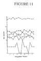
- Figure 11 is a graph plotting the ion counts over 10 s time integrals of the tested apparatuses 68 (with and without bottom plate electrode 70), 76 and 78.
- the symbols in Figure 11 represent the results obtained from the following apparatuses:
- Examples 2-6 relate to the use of droplet generator 32 and levitation device 30 to deposit sample onto a MALDI plate 90 for subsequent mass spectrometry.
- Figures 12A, 12B and 12C are photographs (magnification 5x) illustrating, in sequence, the levitation of charged droplets within the electrodynamic balance 30, and the ejection of a single droplet from within the electrodynamic balance 30.
- the photographs were acquired with a digital camera focused through a single microscope objective lens.
- the motion of a levitated droplet was at 60 Hz, the same frequency as the AC waveform applied to the ring electrodes of the electrodynamic balance.
- the frequency of oscillation of the droplet's trajectory was faster than the shutter speed of the camera, thus the droplets levitated in the electrodynamic balance appear in Figures 12A - 12C as lines.
- Figure 12A represents a DC potential of + 150 V applied to the MALDI plate
- Figure 12B represents a DC potential of +225 V applied to the MALDI plate
- Figure 12C represents a DC potential of + 300 V applied to the MALDI plate.
- This droplet 94 had the highest mass-to-charge ratio of the droplets in the electrodynamic balance 30 (though the parameters for the droplet generator 32 were not varied during the generation of the droplets, there were small variances in the initial size and net charge on each droplet generated, resulting in a range of mass-to-charge ratios for the resulting droplets stored in the electrodynamic balance 30).
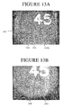
- Figures 13A and 13B illustrate the results of different approaches for deposition of particles onto a MALDI plate 90.
- the photographs of Figures 13A and 13B were acquired by focusing a digital camera through a microscope.
- the magnification of Figure 13A is 20x and the magnification of Figure 13B is 25x.
- the number "45" appearing in Figures 13A and 13B was etched into the MALDI plate by the manufacturer.
- Figure 13A is a photograph of a MALDI plate 90, pre-coated in matrix 100, after the deposition of seven droplets 102 (circled for illustration purposes) simultaneously (or near simultaneously) ejected from the electrodynamic balance 30. Simultaneous ejection of the particles occured with the application of a single large potential pulse.
- the single pulse applied to the MALDI plate 90 was +850 V. This caused near instantaneous removal of the droplets 102 from the electrodynamic balance 30. In doing so, the relative positions of the levitated droplets at the instant of the application of the DC potential pulse became 'printed' onto the MALDI plate 90 as a result of the space charge on each of droplets 102. For example, deposition of the seven droplets 102 simultaneously resulted in droplet impaction over an area of approximately 1.8 x 10 -2 cm 2 with minimum droplet-to-droplet separation exceeding 100 mm.
- the DC potential on the MALDI plate 90 was slowly ramped to a higher potential, enabling the deposition of twenty droplets from the electrodynamic balance 30 onto a spot 104 (circled for illustration purposes) on the MALDI plate sized to less than 3.1 x 10 -4 cm 2 .
- the data of Figure 13B demonstrates that the inherent space charge induced trajectories of multiple droplets levitated in an electrodynamic balance did not interfere with sequential droplet deposition on to a single spot.
- the deposition technique of this invention provides small sample spot sizes required for high sensitivity MALDI applications. Being able to precisely deposit sample onto a small, pre-determined location on a MALDI plate is advantageous since it allows one to conduct more reliable and efficient MALDI mass spectrometry without worry that the sample spot will not be found by the laser.
- Figure 13C is a magnified photograph of a series of droplets 120 that have been deposited from the electrodynamic balance 30 onto a MALDI plate 90 pre-coated with matrix 100 to form a horizontal line. This illustrates that the method of this invention may be used, for example, to prepare a desired array of deposited particles. In such a case, the sample preparation methodology could be interfaced with a separation technique. In Figure 13C , the number "5" was etched into MALDI plate at the time of manufacture.
- An array of particles on a substrate such as the horizontal line array shown in Figure 13C on a MALDI plate 90, could be achieved, for example, by mounting the MALDI plate 90 on a translation stage (not shown). Movement of the translation stage relative to the electrodynamic balance 30 between the ejection of levitated particles (or sub-particles in the case of application of the invention for separation technique purposes) from the electrodynamic balance 30 would result in levitated particle being deposited onto the MALDI plate 90 in an array.
- Figures 14 depicts six consecutive mass spectra (labelled A - F) collected from a single laser spot within which a single droplet had been deposited onto a MALDI plate 90 pre-coated with matrix 100.
- the droplet was generated from a starting solution containing the ester at 1.0 x 10 -3 M, or 460 fmol in a droplet having an initial radius of approximately 48 mm.
- the concentration of NaOH in the starting solution was 2 x 10 -3 M.
- the starting solution was used immediately after preparation, and there was no detectable hydrolysis product in it.
- the droplet was levitated for 9 hours and 50 minutes in the electrodynamic balance. Based on the signal intensity ratio, the composition of the droplet that was deposited was approximately 300 fmol ester and approximately 160 fmol of its hydrolysis product, [ROH + Na + ], both of which were detected as sodium adducts in the spectra.
- Spectra A - F illustrated in Figure 14 are the average spectra of consecutive firings of the laser (with uniform settings) at the droplet deposition point, as follows: Spectra Average Spectra of Laser Firing Nos. A 1 - 256 B 257 - 512 C 513 - 768 D 769 - 1024 E 1025 - 1280 F 1281 - 1536
- Each droplet analysis was performed by centering, and holding an N 2 laser spot fixed on a single position over the site of droplet deposition. Mass spectra were collected with a delayed acquisition time of 25 microseconds.
- Spectra A - F of Figure 14 illustrate that the deposition method of this invention helps suppress matrix cluster ions, yielding "cleaner" spectra for analysis.
- Type I was comprised of combinations of intact molecules and fragments of the matrix clustered with cation(s).
- Spectrum A of Figure 14 is from the first 256 laser shots and, because the size of the deposited droplet was smaller than the laser spot size, there are many background ions of Type I and some of Type II at high relative signal intensity. Peaks 106 represent background ions of Type I.
- Spectrum B shows, relative to spectrum A, a decrease in abundance of background ions of Type I and an increase in the abundance of Type II background ions. This results from the removal of free matrix (by ablation) surrounding the droplet within the laser spot. Peak 108 represents background ions of Type II.
- glycerol in the droplet assists in the increase in S/N and S/B with the increase of laser shot.
- the formation of matrix ions was eventually suppressed, in part because a matrix solution had formed within the glycerol droplet. This would increase the matrix intermolecular separation on the top most layer of the droplet and thus ions were being produced from fluid matrix as opposed to crystalline matrix surface. This decreased the propensity for matrix cluster ion formation.
- a further advantage of the presence of glycerol is that after each laser firing, analyte can diffuse up to the surface forming a more uniform layer of material for each subsequent firing of the laser.
- Figure 15 illustrates a photograph of a MALDI plate 90, after 1,024 laser firings directed towards eight droplets deposited on top of one another on the pre-coated MALDI plate 90.
- the photograph was obtained by focusing a digital camera through a microscope.
- the main photograph 110 is magnified 20x and the insert 112 on the right-hand side of the figure has been magnified 125x.
- the number "65" appearing in the photograph 110 is, again, a number etched into the MALDI plate 90 by the manufacturer.
- a small dark region 114 where the laser was directed is illustrated in Figure 15 .
- the surrounding lighter area is the remaining thin coating of matrix 100.
- the right-hand insert 112 in Figure 15 shows the laser spot 114 at a higher magnification.
- the remnants of the deposited droplets appear to have formed a single droplet 116 positioned within the dark region 114.
- the laser spot size is defined by the dark region 114 because it is the clean stainless steel MALDI plate 90 left behind once the matrix 100 had been ablated away.
- the glycerol droplet deposited on top of the matrix 100 was masking the ablation of the matrix below it while the free matrix 100 around it was removed.
- the presence of matrix 100 remaining below the droplet 116 in Figure 14 was confirmed by the inability to create intact ions from a droplet without an underlying layer of matrix pre-coated onto the MALDI plate.
- the deposited droplets were comprised of glycerol plus any non-volatile solutes that were in the starting solution.
- the glycerol droplet existed for many hours, but once in the vacuum chamber of the mass spectrometer the glycerol was pumped away over a comparatively short time.
- the laser was fired immediately upon insertion of the plate into the vacuum chamber so the glycerol remaining on the plate assisted in fluidizing the solutes within the droplet between firings of the laser, improving signal reproducibility between laser shots.
- the firing of the laser may be delayed until after the glycerol had been pumped away. In such a case, there would remain a thin and concentrated layer of non-volatile solutes that were present in the starting solution.
- Two sets of samples were prepared for deposition onto MALDI plates 90.
- the samples were deposited onto a MALDI plate 90 pre-coated with matrix 100 and in the second instance, the matrix was added directly to the starting solution and the plates 90 were not pre-coated with matrix 100.
- a starting solution comprised of 2 x 10 -4 M ester, 2 x 10 -6 M leucine enkephalin, and 2 x 10 -5 M NaCl in methanol:glycerol at 92:8 % by volume was made.
- the ester acted as an internal check during MALDI-TOF-MS to ensure the laser was directed at the deposited droplets.
- Six droplets were deposited atop one another to form a single droplet on top of a layer of pre-dried crystalline matrix. Each droplet contained approximately 93 fmol ester and approximately 0.930 fmol of leucine enkephalin.
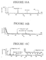
- Figure 16A illustrates the mass spectrum collected from these six droplets. Both the ester and the leucine enkaphalin were cationized by sodium ion, and their S/N were 230 and 83 respectively. The peaks labelled 108 are from background matrix cluster ions.
- Figure 16C is the full mass spectrum of Figure 16B with no mass gate.
- the most intense signal in Figure 16C is due to the sodiated adduct of acetone. This peak' arose because, again, the plate was washed with acetone. By simply washing with de-ionized water and air drying, this peak as well as the [CH 3 COOR + Na + + CH 3 COCH 3 ] peak, could readily be eliminated.
- Each droplet analysis was performed by centering, and holding an N 2 laser spot fixed on a single position over the site of droplet deposition. Mass spectra were collected with a delayed acquisition time of 25 microseconds.
- the glycerol/HCCA matrix solution formed provides a much more uniform matrix from which to desorb.
- 1087 laser shots were fired at the residue of the six droplets in Figure 16B before the S/N decayed below ten.
- the large number of mscans collected from the small amount of material in the collection of six droplets was a consequence of the fluid matrix present in the microspots.
- a sensitive and stable source of ions for MALDI is achieved. Further, the method of this invention will result in achieving lower absolute detection limits and improved quantitation.
- an electrodynamic balance for sample deposition in MALDI mass spectrometry provides a solution to the surface tension problem encountered by handling sample in picoliter volume capillaries.
- the solution is offering a "wall-less" sample preparation procedure that is not limited by capillary tension forces.
- the apparatuses, 68, 76, 78, 81 have been illustrated herein as being vertically-oriented and positioned below a mass spectrometer 65. It will be appreciated by those skilled in the art that the vertical orientation is not necessary to the invention, but that any number of different orientations (e.g. horizontal, etc.) could be utilized.
- Electrodes 83 illustrated in Figures 6 and 7 could be replaced by an octapole arrangement of eight electrodes.
- non-electrodynamic levitation means it would be possible to position a laser to direct a stream at generated particle, thereby inducing a dipole across the neutral particle.
- the laser-induced dipole would capture the particle within the laser stream, allowing levitation of the particle and eventual delivery of the particle to the targe by gradually adjusting the position of the focus of the laser stream until the particle, captured in the laser stream, is delivered to the target (e.g. the orifice of a mass spectrometer, a MALDI plate, etc.).
- An induction electrode would not be included, meaning that the particles generated in this embodiment of the invention would not have a net charge induced thereon.
- the invention will also have application in separating constituent sub-particles from a larger particle.
- the reason for this is that levitating a particle for a period of time in levitation device 30 will allow the particle to reach an equilibrium in which its constituent sub-particles can settle into various layers (which may, for example, comprise aqueous surface layers, layers of adsorbed organic molecules and a solid or liquid core), which can then be sequentially separated out of the levitated particle and analyzed independently of the other constituent sub-particles.
- the levitated particle could be subjected to a pulsed laser beam to cause the separation of the layers.
- the layers could be separated by Coloumbic fissioning following the induction of a net charge onto the discrete particle (as described above) or by desorption.
- the various layers and core could be sequentially deposited onto a MALDI plate, as described herein, and then subjected to MALDI mass spectrometry.
- a levitated droplet may be subjecte.g. to a flow of gas to control (e.g. promote or retard) the evaporation rate of the solvent in the droplet.
- control e.g. promote or retard
- Another possible application of this invention is as a "wall-less" chemical reaction vessel.
- reactants e.g. droplets or particles
- the levitated droplets/particles could then be spatially manipulated in the electrodynamic balance (by varying the potential of the electrodes) to coalesce.
- the advantage to this technique is that the surface-to-volume ratio is enhanced (relative to performing the same raction in a traditional reaction vessel).
- This adaption of the invention could have many application, such as medical diagnostic purposes. A variation of this strategy would be to coat a cell, or a small population of cells that are levitated with matrix.
- the method of coating the surface of a cell can enable detection of the molecules that reside on the surface of the cell. With a cell levitated, it would be possible to subject the cell to various stresses, such as gas phase chemical reagents, or though a coalescence of two droplets, the introduction of a solution phase reagent. The latter application can be used to bring a digestive enzyme to the surface of the cell and generate peptide fragments from the membrane-proteins that protrude out of the cell.
- this approach could be employed to add matrix to droplets prior to deposition onto a MALDI plate.
- an analyte containing droplet and a matrix containing droplet, both independently generated by droplet generator 32 could be spatially manipulated and made to coalesce into a single droplet within levitation device 30 while levitating prior to deposition onto the MALDI plate.
- a particle could be coated with matrix following the deposition of the particle onto the MALDI plate 90.
- the particle is deposited onto the MALDI plate as aforesaid.
- a separate particle, containing the matrix would then be independently generated by droplet generator 32 (or another particle generator) and levitated as aforesaid.
- the levitated matrix-containing particle would then be deposited onto the deposited particle (containing analyte), thereby coating the first droplet on the MALDI plate.
- the invention could have application for subjecting a deposited particle to a test material applied to a substrate.
- a test material applied to a substrate.
- materials having biological, chemical or physical origin to a plate and then causing a particle to be delivered to that test material for subsequent analysis of the reaction.
- Such a reaction could take place in recessed wells of a MALDI plate by applying the test material to the wells before depositing the particles into those wells using the apparatus and method of this invention.
- This application of the invention could be advantageous for testing the effectiveness of drugs and other similar purposes.
- the invention could have application for polymerizing progeny droplets, which at the moment of their formation, are approximately 100-1000 run in diameter. With care, it would be possible to allow these progeny droplets to desolvate to smaller diameters before polymerizing their surface to encapsulate the contents of these droplets. This procedure could be used to prepare round nanometer sized materials that could be designed to be either hollow or solid.
Landscapes
- Physics & Mathematics (AREA)
- Spectroscopy & Molecular Physics (AREA)
- Electromagnetism (AREA)
- Engineering & Computer Science (AREA)
- Plasma & Fusion (AREA)
- Chemical & Material Sciences (AREA)
- Analytical Chemistry (AREA)
- Other Investigation Or Analysis Of Materials By Electrical Means (AREA)
- Electron Tubes For Measurement (AREA)
- Physical Or Chemical Processes And Apparatus (AREA)
Claims (66)
- Eine Vorrichtung zum Herstellen eines diskreten Teilchens und Abgeben des Teilchens an ein Ziel zur nachfolgenden Analyse oder Manipulation, wobei die Vorrichtung Folgendes beinhaltet:(a) einen Teilchengenerator (32) zum Erzeugen eines diskreten Teilchens, wobei der Teilchengenerator ein Tröpfchengenerator zum Erzeugen eines diskreten Tröpfchens, das einen Analyten und ein Lösungsmittel beinhaltet, ist,(b) eine Schwebeeinrichtung (30) zum Schwebenlassen des diskreten Teilchens und(c) ein Abgabemittel zum Abgeben des diskreten Teilchens an das Ziel, dadurch gekennzeichnet, dass sich das Ziel in einer von der Schwebeeinrichtung entfernten Position befindet, und wobei das Abgabemittel das diskrete Teilchen zur nachfolgenden Analyse oder Manipulation steuerbar an das Ziel abgibt.
- Vorrichtung gemäß Anspruch 1, wobei das Ziel ein Substrat ist, das ein Material beinhaltet, welches zur Ablagerung des Teilchens darauf geeignet ist.
- Vorrichtung gemäß Anspruch 1, die ein atmosphärisches Gas messendes Massenspektrometer (31) beinhaltet, und wobei das Ziel eine Öffnung (33) in Verbindung mit einer Vakuumkammer (37) des Massenspektrometers ist.
- Vorrichtung gemäß Anspruch 2, die ein Substrat beinhaltet, und wobei das Ziel das Substrat ist.
- Vorrichtung gemäß Anspruch 4, wobei das Substrat eine Platte ist, die zu einer massenspektrometrischen Analyse mit matrixunterstützter Laser-Desorption und Ionisation geeignet ist.
- Vorrichtung gemäß Anspruch 5, wobei die Platte ein Material zum Aufnehmen des Teilchens beinhaltet.
- Vorrichtung gemäß Anspruch 6, wobei das Material eine Matrix ist.
- Vorrichtung gemäß Anspruch 5, wobei das Teilchen eine Matrix beinhaltet.
- Vorrichtung gemäß Anspruch 5, wobei die Platte mindestens eine ausgesparte Vertiefung beinhaltet.
- Vorrichtung gemäß Anspruch 1, die ferner eine Induktionselektrode (52) zum Induzieren einer Nettoladung auf dem diskreten Teilchen beinhaltet.
- Vorrichtung gemäß Anspruch 10, wobei die Schwebeeinrichtung das diskrete Teilchen im Anschluss an die Induktion der Nettoladung elektrodynamisch schweben lässt.
- Vorrichtung gemäß Anspruch 11, wobei das Abgabemittel eine Elektrodenanordnung ist.
- Vorrichtung gemäß Anspruch 12, wobei die Schwebeeinrichtung die Elektrodenanordnung beinhaltet.
- Vorrichtung gemäß Anspruch 11, wobei die Schwebeeinrichtung eine elektrodynamische Waage ist.
- Vorrichtung gemäß Anspruch 14, wobei die elektrodynamische Waage ein Paar getrennter Schwebeelektroden ist.
- Vorrichtung gemäß Anspruch 15, wobei das Paar Schwebeelektroden ein Paar erster Ringelektroden (48, 50) ist, die sich in parallelen Ebenen erstrecken.
- Vorrichtung gemäß Anspruch 16, wobei über die ersten Ringelektroden eine Spannungsdifferenz aufrechterhalten wird.
- Vorrichtung gemäß Anspruch 10, wobei sich die Induktionselektrode nahe dem Teilchengenerator befindet.
- Vorrichtung gemäß Anspruch 1, wobei die Vorrichtung eine Kammer beinhaltet, die die Schwebeeinrichtung im Wesentlichen umschließt, und wobei sich das Ziel außerhalb der Kammer befindet.
- Vorrichtung gemäß Anspruch 12, wobei die Elektrodenanordnung eine erste Plattenelektrode, die zwischen dem Teilchengenerator und der Schwebeeinrichtung positioniert ist, und eine zweite Plattenelektrode, die zwischen der Schwebeeinrichtung und dem Ziel positioniert ist, beinhaltet.
- Vorrichtung gemäß Anspruch 20, wobei die erste Plattenelektrode und die zweite Plattenelektrode jeweils darin gebildete Durchlässe aufweisen, um den Durchgang des diskreten Teilchens durch diese zu gestatten.
- Vorrichtung gemäß Anspruch 1, wobei das Abgabemittel bei atmosphärischem Druck betriebsfähig ist.
- Vorrichtung gemäß Anspruch 1, wobei das Abgabemittel eine Elektrodenanordnung beinhaltet, die einen Stapel getrennter zweiter Ringelektroden, die in parallelen Ebenen zwischen der Schwebeeinrichtung und dem Ziel angeordnet sind, beinhaltet.
- Vorrichtung gemäß Anspruch 23, wobei die zweiten Ringelektroden in der Richtung von der Schwebeeinrichtung zu der Öffnung hin im Durchmesser progressiv kleiner sind.
- Vorrichtung gemäß Anspruch 24, die vier separate zweite Ringelektroden beinhaltet, die jeweils mit ungefähr 3 mm Abstand voneinander angeordnet sind.
- Vorrichtung gemäß Anspruch 17, wobei die Spannungsdifferenz über die ersten Ringelektroden ungefähr 20 V beträgt.
- Vorrichtung gemäß Anspruch 1, wobei das Abgabemittel zwischen der Schwebeeinrichtung und dem Ziel eine Quadrupolelektrodenanordnung beinhaltet.
- Vorrichtung gemäß Anspruch 14, wobei die elektrodynamische Waage bei variablen Frequenzen betriebsfähig ist.
- Vorrichtung gemäß Anspruch 4, wobei das Abgabemittel eine erste Plattenelektrode, die zwischen dem Teilchengenerator und der Schwebeeinrichtung positioniert ist, und eine zweite Plattenelektrode, die zwischen der Schwebeeinrichtung und dem Substrat positioniert ist, beinhaltet.
- Vorrichtung gemäß Anspruch 29, wobei die erste Plattenelektrode und die zweite Plattenelektrode jeweils darin gebildete Durchlässe aufweisen, um den Durchgang des diskreten Teilchens durch diese zu gestatten.
- Vorrichtung gemäß Anspruch 4, die einen Verschiebetisch beinhaltet, wobei das Substrat auf dem Verschiebetisch positioniert wird und wobei der Verschiebetisch relativ zu der Schwebeeinrichtung steuerbar beweglich ist.
- Vorrichtung gemäß Anspruch 1, wobei der Tröpfchengenerator eine hohle Düse mit flacher Spitze beinhaltet, durch die das diskrete Tröpfchen ausgegeben wird.
- Vorrichtung gemäß Anspruch 1, wobei das Abgabemittel einen Laser mit einem einstellbaren Brennpunkt beinhaltet.
- Vorrichtung gemäß Anspruch 1, wobei die Schwebeeinrichtung ein Laser ist.
- Vorrichtung gemäß Anspruch 34, wobei die Schwebeeinrichtung das Abgabemittel beinhaltet.
- Vorrichtung gemäß Anspruch 35, wobei der Laser einen einstellbaren Brennpunkt aufweist.
- Vorrichtung gemäß Anspruch 4, die ferner einen Laser zum Trennen des Teilchens in Subteilchen beinhaltet, wobei das Abgabemittel die Subteilchen zur Ablagerung in einer Gruppierung darauf an das Substrat abgibt.
- Vorrichtung gemäß Anspruch 2, wobei das Material ein Testmaterial mit einem biologischen, chemischen oder physikalischen Ursprung ist.
- Ein Verfahren zum Produzieren eines diskreten Teilchens und Abgeben des Teilchens an ein Ziel zur nachfolgenden Analyse oder Manipulation, wobei das Verfahren Folgendes beinhaltet:(a) Erzeugen eines diskreten Teilchens, wobei das Teilchen ein Tröpfchen ist, das einen Analyten und ein Lösungsmittel beinhaltet,(b) Schwebenlassen des diskreten Teilchens unter Verwendung einer Schwebeeinrichtung; und(c) Wegbewegen des diskreten Teilchens von der Schwebeeinrichtung, dadurch gekennzeichnet, dass das diskrete Teilchen zur nachfolgenden Analyse oder Manipulation steuerbar an ein entfernt gelegenes Ziel abgegeben wird.
- Verfahren gemäß Anspruch 39, das vor dem Schwebenlassen des diskreten Teilchens das Induzieren einer Nettoladung auf dem diskreten Teilchen beinhaltet.
- Verfahren gemäß Anspruch 40, wobei die Schwebeeinrichtung das diskrete Teilchen elektrodynamisch schweben lässt.
- Verfahren gemäß Anspruch 41, wobei das diskrete Teilchen unter Verwendung einer Elektrodenanordnung an das Ziel abgegeben wird.
- Verfahren gemäß Anspruch 39, das den Schritt des Abgebens des diskreten Teilchens an ein atmosphärisches Gas messendes Massenspektrometer zur massenspektrometrischen Analyse beinhaltet, wobei das Ziel eine Öffnung in Verbindung mit dem atmosphärisches Gas messenden Massenspektrometer ist.
- Verfahren gemäß Anspruch 39, wobei das Ziel ein Substrat beinhaltet, das aus einem zur Ablagerung des Teilchens darauf geeigneten Material gebildet ist.
- Verfahren gemäß Anspruch 44, wobei das Substrat eine Platte ist, wobei das Verfahren den Schritt beinhaltet, dass die Platte einer massenspektrometrischen Analyse mit matrixunterstützter Laser-Desorption und Ionisation unterzogen wird.
- Verfahren gemäß Anspruch 45, das den Schritt des Auftragens eines Materials auf die Platte zum Aufnehmen des Teilchens beinhaltet.
- Verfahren gemäß Anspruch 46, wobei das Material eine Matrix ist.
- Verfahren gemäß Anspruch 45, wobei das Teilchen eine Matrix beinhaltet.
- Verfahren gemäß Anspruch 39, wobei das diskrete Tröpfchen über einen Zeitraum, der ausreicht, um mindestens eine teilweise Desolvatisierung des diskreten Tröpfchens zu gestatten, elektrodynamisch schweben gelassen wird.
- Verfahren gemäß Anspruch 44, das den Schritt des Bewegens des Substrats relativ zu der Schwebeeinrichtung beinhaltet.
- Verfahren gemäß Anspruch 39, wobei Schritt (c) bei atmosphärischem Druck ausgeführt wird.
- Verfahren gemäß Anspruch 39, wobei die Schwebeeinrichtung eine elektrodynamische Waage beinhaltet und das diskrete Teilchen schweben gelassen wird, indem über die elektrodynamische Waage eine konstante Spannungsdifferenz angelegt wird.
- Verfahren gemäß Anspruch 40, wobei die Nettoladung induziert wird, wenn das Teilchen erzeugt wird.
- Verfahren gemäß Anspruch 49, das den Schritt beinhaltet, dass das diskrete Teilchen einem Gas ausgesetzt wird, während das diskrete Teilchen schweben gelassen wird, um die Evaporationsrate des Lösungsmittels zu steuern.
- Verfahren gemäß Anspruch 49, wobei die Desolvatisierung eine Coulomb-Spaltung des Tröpfchens in eine Vielzahl von Tochtertröpfchen bewirkt.
- Verfahren gemäß Anspruch 55, wobei jedes der Tochtertröpfchen über einen Zeitraum, der ausreicht, um die Desolvatisierung dieses Tochtertröpfchens zu ermöglichen, schweben gelassen wird, so dass ein beliebiger Analyt in diesem Tochtertröpfchen geladen wird, wodurch sich eine Quelle an Ionen ergibt.
- Verfahren gemäß Anspruch 56, das den Schritt des Abgebens der Tochtertröpfchen von der Schwebeeinrichtung an das Ziel zur nachfolgenden Analyse oder Manipulation beinhaltet.
- Verfahren gemäß Anspruch 57, das den Schritt beinhaltet, dass die Ionen einer massenspektrometrischen Analyse unterzogen werden.
- Verfahren gemäß Anspruch 58, wobei die Ionen nach Schritt (c) auf einer Platte abgelagert werden und wobei die massenspektrometrische Analyse eine massenspektrometrische Analyse mit matrixunterstützter Laser-Desorption und Ionisation beinhaltet.
- Verfahren gemäß Anspruch 59, wobei die Matrix auf die Platte aufgetragen wird, bevor die Ionen abgelagert werden.
- Verfahren gemäß Anspruch 59, wobei die Matrix mit den Ionen auf die Platte aufgetragen wird.
- Verfahren gemäß Anspruch 60, wobei die Ionen nacheinander auf der Platte abgelagert werden.
- Verfahren gemäß Anspruch 44, das das Wiederholen der Schritte gemäß Anspruch 39 beinhaltet, während das Substrat relativ zu der Schwebeeinrichtung bewegt wird, um eine Gruppierung von Teilchen auf dem Substrat abzulagern.
- Verfahren gemäß Anspruch 39, wobei das diskrete Tröpfchen von der Schwebeeinrichtung zu dem Ziel bewegt wird, indem das diskrete Teilchen in einem Laserstrahl gefangen und der Laserstrahl zu dem Ziel bewegt wird.
- Verfahren gemäß Anspruch 40, wobei die Schwebeeinrichtung zum Schwebenlassen des diskreten Teilchens einen Laser beinhaltet.
- Verfahren gemäß Anspruch 45, wobei das Material ein Testmaterial mit einem biologischen, chemischen oder physikalischen Ursprung ist.
Applications Claiming Priority (3)
| Application Number | Priority Date | Filing Date | Title |
|---|---|---|---|
| US24205800P | 2000-10-23 | 2000-10-23 | |
| US242058P | 2000-10-23 | ||
| PCT/CA2001/001496 WO2002035553A2 (en) | 2000-10-23 | 2001-10-23 | Method and apparatus for producing a discrete particle |
Publications (2)
| Publication Number | Publication Date |
|---|---|
| EP1330829A2 EP1330829A2 (de) | 2003-07-30 |
| EP1330829B1 true EP1330829B1 (de) | 2009-08-26 |
Family
ID=22913288
Family Applications (1)
| Application Number | Title | Priority Date | Filing Date |
|---|---|---|---|
| EP01981998A Expired - Lifetime EP1330829B1 (de) | 2000-10-23 | 2001-10-23 | Verfahren und vorrichtung zur erzeugung eines diskreten teilchens |
Country Status (8)
| Country | Link |
|---|---|
| US (1) | US7785897B2 (de) |
| EP (1) | EP1330829B1 (de) |
| JP (2) | JP4527353B2 (de) |
| AT (1) | ATE441190T1 (de) |
| AU (1) | AU2002213699A1 (de) |
| CA (1) | CA2462265C (de) |
| DE (1) | DE60139704D1 (de) |
| WO (1) | WO2002035553A2 (de) |
Families Citing this family (21)
| Publication number | Priority date | Publication date | Assignee | Title |
|---|---|---|---|---|
| WO2004075208A2 (en) * | 2003-02-24 | 2004-09-02 | Simon Fraser University | Formation of closely packed microspots and irradiation of same |
| JP4552053B2 (ja) * | 2006-10-05 | 2010-09-29 | 独立行政法人 日本原子力研究開発機構 | ナトリウム漏えい検知方法及び装置 |
| US9492887B2 (en) * | 2010-04-01 | 2016-11-15 | Electro Scientific Industries, Inc. | Touch screen interface for laser processing |
| US9552973B2 (en) * | 2010-09-02 | 2017-01-24 | University Of The Sciences In Philadelphia | System and method for ionization of molecules for mass spectrometry and ion mobility spectrometry |
| WO2012047465A1 (en) * | 2010-09-27 | 2012-04-12 | Dh Technologies Development Pte. Ltd. | Method and system for providing a dual curtain gas to a mass spectrometry system |
| US8673120B2 (en) * | 2011-01-04 | 2014-03-18 | Jefferson Science Associates, Llc | Efficient boron nitride nanotube formation via combined laser-gas flow levitation |
| US9744542B2 (en) | 2013-07-29 | 2017-08-29 | Apeel Technology, Inc. | Agricultural skin grafting |
| EP3298024B1 (de) | 2015-05-20 | 2020-04-01 | Apeel Technology, Inc. | Pflanzenextraktzusammensetzungen und verfahren zur herstellung davon |
| US11049703B2 (en) * | 2015-08-21 | 2021-06-29 | PharmaCadence Analytical Services, LLC | Methods of evaluating performance of an atmospheric pressure ionization system |
| EP3349589B1 (de) | 2015-09-16 | 2022-12-14 | Apeel Technology, Inc. | Verfahren zur bildung einer schutzbeschichtung durch auftragen von fettsäureglyceridverbindungen auf eine oberfläche |
| ES2797697T3 (es) | 2015-12-10 | 2020-12-03 | Apeel Tech Inc | Proceso para despolimerizar cutina |
| WO2017132281A1 (en) | 2016-01-26 | 2017-08-03 | Apeel Technology, Inc. | Method for preparing and preserving sanitized products |
| JP6609379B2 (ja) * | 2016-08-19 | 2019-11-20 | 株式会社日立ハイテクノロジーズ | イオン分析装置 |
| JP7194678B2 (ja) | 2016-11-17 | 2022-12-22 | アピール テクノロジー,インコーポレイテッド | 植物抽出物から形成される組成物及びその調製方法 |
| US12245605B2 (en) | 2018-09-05 | 2025-03-11 | Apeel Technology, Inc. | Compounds and formulations for protective coatings |
| JP7578707B2 (ja) | 2020-03-04 | 2024-11-06 | アピール テクノロジー,インコーポレイテッド | 被覆された農産物及び対応する方法 |
| MX2023004343A (es) | 2020-10-30 | 2023-05-08 | Apeel Tech Inc | Composiciones y metodos de preparacion de las mismas. |
| CN113358945B (zh) * | 2021-07-01 | 2023-07-28 | 兰州空间技术物理研究所 | 一种多功能空间高速尘埃特性探测器 |
| CN118159138A (zh) | 2021-09-08 | 2024-06-07 | 阿比尔技术公司 | 用于保护性涂层的化合物和制剂 |
| GB202403368D0 (en) | 2024-03-08 | 2024-04-24 | Univ Bristol | Delivery of picolitre droplets to mass spectrometer |
| CN119984737B (zh) * | 2025-02-20 | 2025-12-02 | 西安交通大学 | 一种研究液滴热毛细现象的可视化实验系统及方法 |
Family Cites Families (16)
| Publication number | Priority date | Publication date | Assignee | Title |
|---|---|---|---|---|
| JP2569570B2 (ja) | 1987-06-19 | 1997-01-08 | 株式会社島津製作所 | 固体クロマトグラフィ質量分析方法 |
| US5352892A (en) | 1992-05-29 | 1994-10-04 | Cornell Research Foundation, Inc. | Atmospheric pressure ion interface for a mass analyzer |
| US5331159A (en) * | 1993-01-22 | 1994-07-19 | Hewlett Packard Company | Combined electrospray/particle beam liquid chromatography/mass spectrometer |
| US5532140A (en) * | 1994-03-23 | 1996-07-02 | The United States Of America As Represented By The Secretary Of The Army | Method and apparatus for suspending microparticles |
| JP3663716B2 (ja) | 1996-02-05 | 2005-06-22 | 株式会社日立製作所 | 四重極イオン蓄積リング |
| DE19628178C1 (de) * | 1996-07-12 | 1997-09-18 | Bruker Franzen Analytik Gmbh | Verfahren zum Beladen von Probenträgern für Massenspektrometer |
| JPH1048110A (ja) | 1996-07-31 | 1998-02-20 | Shimadzu Corp | Maldi−tof質量分析装置用サンプラ |
| JPH10239298A (ja) * | 1997-02-26 | 1998-09-11 | Shimadzu Corp | 液体クロマトグラフ質量分析装置 |
| US6054709A (en) * | 1997-12-05 | 2000-04-25 | The University Of British Columbia | Method and apparatus for determining the rates of reactions in liquids by mass spectrometry |
| JP3561422B2 (ja) | 1998-08-20 | 2004-09-02 | 日本電子株式会社 | 大気圧イオン源 |
| JP3379485B2 (ja) * | 1998-09-02 | 2003-02-24 | 株式会社島津製作所 | 質量分析装置 |
| JP3571546B2 (ja) | 1998-10-07 | 2004-09-29 | 日本電子株式会社 | 大気圧イオン化質量分析装置 |
| JP3758382B2 (ja) | 1998-10-19 | 2006-03-22 | 株式会社島津製作所 | 質量分析装置 |
| GB2346730B (en) | 1999-02-11 | 2003-04-23 | Masslab Ltd | Ion source for mass analyser |
| US6633031B1 (en) | 1999-03-02 | 2003-10-14 | Advion Biosciences, Inc. | Integrated monolithic microfabricated dispensing nozzle and liquid chromatography-electrospray system and method |
| JP3650551B2 (ja) * | 1999-09-14 | 2005-05-18 | 株式会社日立製作所 | 質量分析計 |
-
2001
- 2001-10-23 JP JP2002538445A patent/JP4527353B2/ja not_active Expired - Fee Related
- 2001-10-23 WO PCT/CA2001/001496 patent/WO2002035553A2/en not_active Ceased
- 2001-10-23 AT AT01981998T patent/ATE441190T1/de not_active IP Right Cessation
- 2001-10-23 CA CA2462265A patent/CA2462265C/en not_active Expired - Fee Related
- 2001-10-23 DE DE60139704T patent/DE60139704D1/de not_active Expired - Lifetime
- 2001-10-23 EP EP01981998A patent/EP1330829B1/de not_active Expired - Lifetime
- 2001-10-23 AU AU2002213699A patent/AU2002213699A1/en not_active Abandoned
- 2001-10-23 US US10/399,823 patent/US7785897B2/en not_active Expired - Fee Related
-
2007
- 2007-07-04 JP JP2007175834A patent/JP2007266007A/ja active Pending
Also Published As
| Publication number | Publication date |
|---|---|
| JP2007266007A (ja) | 2007-10-11 |
| EP1330829A2 (de) | 2003-07-30 |
| WO2002035553A2 (en) | 2002-05-02 |
| ATE441190T1 (de) | 2009-09-15 |
| US20040063113A1 (en) | 2004-04-01 |
| US7785897B2 (en) | 2010-08-31 |
| WO2002035553A3 (en) | 2002-09-06 |
| CA2462265A1 (en) | 2002-05-02 |
| DE60139704D1 (de) | 2009-10-08 |
| AU2002213699A1 (en) | 2002-05-06 |
| JP4527353B2 (ja) | 2010-08-18 |
| CA2462265C (en) | 2013-11-19 |
| JP2004511894A (ja) | 2004-04-15 |
Similar Documents
| Publication | Publication Date | Title |
|---|---|---|
| US7785897B2 (en) | Method and apparatus for producing a discrete droplet for subsequent analysis or manipulation | |
| EP1380045B1 (de) | Piezoelektrisch geladene tröpfchenquelle | |
| US10796894B2 (en) | System and method for ionization of molecules for mass spectrometry and ion mobility spectrometry | |
| US6649907B2 (en) | Charge reduction electrospray ionization ion source | |
| EP1764825B1 (de) | Hybrid Ionenmobilitäts- und Massenspektrometer | |
| US5811800A (en) | Temporary storage of ions for mass spectrometric analyses | |
| US6974957B2 (en) | Ionization device for aerosol mass spectrometer and method of ionization | |
| JP3601834B2 (ja) | Maldi分析の方法および装置 | |
| JP6698698B2 (ja) | オーバーサンプル型飛行時間質量分析 | |
| EP0546097A1 (de) | Verfahren und vorrichtung zur spurenanalyse | |
| EP2545581A1 (de) | Analytsprühemitter und verfahren zur massenspektrometischen analyse | |
| WO2000017908A9 (en) | Charge reduction in electrospray mass spectrometry | |
| Bogan et al. | MALDI-TOF-MS analysis of droplets prepared in an electrodynamic balance:“wall-less” sample preparation | |
| US20080067345A1 (en) | Method for creating multiply charged ions for MALDI mass spectrometry (ESMALDI) | |
| Bogan et al. | Wall-less sample preparation of μ m-sized sample spots for femtomole detection limits of proteins from liquid based UV-MALDI matrices | |
| US7750312B2 (en) | Method and apparatus for generating ions for mass analysis | |
| US20060110833A1 (en) | Method and apparatus for coupling an analyte supply to an electrodynamic droplet processor | |
| CA2324911C (en) | Method and apparatus for producing a discrete particle | |
| RU2124783C1 (ru) | Способ анализа макромолекул биополимеров | |
| US7824920B2 (en) | Method of mass spectrometric analysis from closely packed microspots by their simultaneous laser irradiation | |
| EP2011139A2 (de) | Verfahren und vorrichtung zur erzeugung von ionen zur massenanalyse | |
| Li | Development of Membrane Funnel-based Spray Ionization Mass Spectrometry | |
| Mackay | TOWARDS CHEMICAL PROFILING AT THE CELLULAR |
Legal Events
| Date | Code | Title | Description |
|---|---|---|---|
| PUAI | Public reference made under article 153(3) epc to a published international application that has entered the european phase |
Free format text: ORIGINAL CODE: 0009012 |
|
| 17P | Request for examination filed |
Effective date: 20030523 |
|
| AK | Designated contracting states |
Designated state(s): AT BE CH CY DE DK ES FI FR GB GR IE IT LI LU MC NL PT SE TR |
|
| AX | Request for extension of the european patent |
Extension state: AL LT LV MK RO SI |
|
| RIN1 | Information on inventor provided before grant (corrected) |
Inventor name: BOGAN, MICHAEL Inventor name: FENG, XIAO,SIMON FRASER UNIVERSITY Inventor name: AGNES, GEORGE |
|
| 17Q | First examination report despatched |
Effective date: 20030929 |
|
| R17D | Deferred search report published (corrected) |
Effective date: 20020906 |
|
| 17Q | First examination report despatched |
Effective date: 20030929 |
|
| GRAP | Despatch of communication of intention to grant a patent |
Free format text: ORIGINAL CODE: EPIDOSNIGR1 |
|
| GRAS | Grant fee paid |
Free format text: ORIGINAL CODE: EPIDOSNIGR3 |
|
| RAP1 | Party data changed (applicant data changed or rights of an application transferred) |
Owner name: SIMON FRASER UNIVERSITY |
|
| GRAA | (expected) grant |
Free format text: ORIGINAL CODE: 0009210 |
|
| AK | Designated contracting states |
Kind code of ref document: B1 Designated state(s): AT BE CH CY DE DK ES FI FR GB GR IE IT LI LU MC NL PT SE TR |
|
| REG | Reference to a national code |
Ref country code: GB Ref legal event code: FG4D |
|
| REG | Reference to a national code |
Ref country code: CH Ref legal event code: EP |
|
| REG | Reference to a national code |
Ref country code: IE Ref legal event code: FG4D |
|
| REF | Corresponds to: |
Ref document number: 60139704 Country of ref document: DE Date of ref document: 20091008 Kind code of ref document: P |
|
| PG25 | Lapsed in a contracting state [announced via postgrant information from national office to epo] |
Ref country code: AT Free format text: LAPSE BECAUSE OF FAILURE TO SUBMIT A TRANSLATION OF THE DESCRIPTION OR TO PAY THE FEE WITHIN THE PRESCRIBED TIME-LIMIT Effective date: 20090826 Ref country code: SE Free format text: LAPSE BECAUSE OF FAILURE TO SUBMIT A TRANSLATION OF THE DESCRIPTION OR TO PAY THE FEE WITHIN THE PRESCRIBED TIME-LIMIT Effective date: 20090826 Ref country code: FI Free format text: LAPSE BECAUSE OF FAILURE TO SUBMIT A TRANSLATION OF THE DESCRIPTION OR TO PAY THE FEE WITHIN THE PRESCRIBED TIME-LIMIT Effective date: 20090826 |
|
| NLV1 | Nl: lapsed or annulled due to failure to fulfill the requirements of art. 29p and 29m of the patents act | ||
| PG25 | Lapsed in a contracting state [announced via postgrant information from national office to epo] |
Ref country code: NL Free format text: LAPSE BECAUSE OF FAILURE TO SUBMIT A TRANSLATION OF THE DESCRIPTION OR TO PAY THE FEE WITHIN THE PRESCRIBED TIME-LIMIT Effective date: 20090826 |
|
| PG25 | Lapsed in a contracting state [announced via postgrant information from national office to epo] |
Ref country code: CY Free format text: LAPSE BECAUSE OF FAILURE TO SUBMIT A TRANSLATION OF THE DESCRIPTION OR TO PAY THE FEE WITHIN THE PRESCRIBED TIME-LIMIT Effective date: 20090826 Ref country code: PT Free format text: LAPSE BECAUSE OF FAILURE TO SUBMIT A TRANSLATION OF THE DESCRIPTION OR TO PAY THE FEE WITHIN THE PRESCRIBED TIME-LIMIT Effective date: 20091228 |
|
| PG25 | Lapsed in a contracting state [announced via postgrant information from national office to epo] |
Ref country code: ES Free format text: LAPSE BECAUSE OF FAILURE TO SUBMIT A TRANSLATION OF THE DESCRIPTION OR TO PAY THE FEE WITHIN THE PRESCRIBED TIME-LIMIT Effective date: 20091207 Ref country code: DK Free format text: LAPSE BECAUSE OF FAILURE TO SUBMIT A TRANSLATION OF THE DESCRIPTION OR TO PAY THE FEE WITHIN THE PRESCRIBED TIME-LIMIT Effective date: 20090826 |
|
| PG25 | Lapsed in a contracting state [announced via postgrant information from national office to epo] |
Ref country code: MC Free format text: LAPSE BECAUSE OF NON-PAYMENT OF DUE FEES Effective date: 20091031 |
|
| REG | Reference to a national code |
Ref country code: CH Ref legal event code: PL |
|
| PG25 | Lapsed in a contracting state [announced via postgrant information from national office to epo] |
Ref country code: BE Free format text: LAPSE BECAUSE OF FAILURE TO SUBMIT A TRANSLATION OF THE DESCRIPTION OR TO PAY THE FEE WITHIN THE PRESCRIBED TIME-LIMIT Effective date: 20090826 |
|
| PLBE | No opposition filed within time limit |
Free format text: ORIGINAL CODE: 0009261 |
|
| STAA | Information on the status of an ep patent application or granted ep patent |
Free format text: STATUS: NO OPPOSITION FILED WITHIN TIME LIMIT |
|
| 26N | No opposition filed |
Effective date: 20100527 |
|
| PG25 | Lapsed in a contracting state [announced via postgrant information from national office to epo] |
Ref country code: IE Free format text: LAPSE BECAUSE OF NON-PAYMENT OF DUE FEES Effective date: 20091023 Ref country code: GR Free format text: LAPSE BECAUSE OF FAILURE TO SUBMIT A TRANSLATION OF THE DESCRIPTION OR TO PAY THE FEE WITHIN THE PRESCRIBED TIME-LIMIT Effective date: 20091127 Ref country code: CH Free format text: LAPSE BECAUSE OF NON-PAYMENT OF DUE FEES Effective date: 20091031 Ref country code: LI Free format text: LAPSE BECAUSE OF NON-PAYMENT OF DUE FEES Effective date: 20091031 |
|
| PG25 | Lapsed in a contracting state [announced via postgrant information from national office to epo] |
Ref country code: IT Free format text: LAPSE BECAUSE OF FAILURE TO SUBMIT A TRANSLATION OF THE DESCRIPTION OR TO PAY THE FEE WITHIN THE PRESCRIBED TIME-LIMIT Effective date: 20090826 |
|
| PG25 | Lapsed in a contracting state [announced via postgrant information from national office to epo] |
Ref country code: LU Free format text: LAPSE BECAUSE OF NON-PAYMENT OF DUE FEES Effective date: 20091023 |
|
| PG25 | Lapsed in a contracting state [announced via postgrant information from national office to epo] |
Ref country code: TR Free format text: LAPSE BECAUSE OF FAILURE TO SUBMIT A TRANSLATION OF THE DESCRIPTION OR TO PAY THE FEE WITHIN THE PRESCRIBED TIME-LIMIT Effective date: 20090826 |
|
| PGFP | Annual fee paid to national office [announced via postgrant information from national office to epo] |
Ref country code: FR Payment date: 20131017 Year of fee payment: 13 Ref country code: DE Payment date: 20131029 Year of fee payment: 13 Ref country code: GB Payment date: 20131028 Year of fee payment: 13 |
|
| REG | Reference to a national code |
Ref country code: DE Ref legal event code: R119 Ref document number: 60139704 Country of ref document: DE |
|
| GBPC | Gb: european patent ceased through non-payment of renewal fee |
Effective date: 20141023 |
|
| PG25 | Lapsed in a contracting state [announced via postgrant information from national office to epo] |
Ref country code: GB Free format text: LAPSE BECAUSE OF NON-PAYMENT OF DUE FEES Effective date: 20141023 Ref country code: DE Free format text: LAPSE BECAUSE OF NON-PAYMENT OF DUE FEES Effective date: 20150501 |
|
| REG | Reference to a national code |
Ref country code: FR Ref legal event code: ST Effective date: 20150630 |
|
| PG25 | Lapsed in a contracting state [announced via postgrant information from national office to epo] |
Ref country code: FR Free format text: LAPSE BECAUSE OF NON-PAYMENT OF DUE FEES Effective date: 20141031 |