EP1331360A2 - Disposition des aubes statoriques et rotoriques au niveau de l'échappement d'une turbine - Google Patents
Disposition des aubes statoriques et rotoriques au niveau de l'échappement d'une turbine Download PDFInfo
- Publication number
- EP1331360A2 EP1331360A2 EP03250341A EP03250341A EP1331360A2 EP 1331360 A2 EP1331360 A2 EP 1331360A2 EP 03250341 A EP03250341 A EP 03250341A EP 03250341 A EP03250341 A EP 03250341A EP 1331360 A2 EP1331360 A2 EP 1331360A2
- Authority
- EP
- European Patent Office
- Prior art keywords
- aerofoil
- blade
- vane
- variation
- gas turbine
- Prior art date
- Legal status (The legal status is an assumption and is not a legal conclusion. Google has not performed a legal analysis and makes no representation as to the accuracy of the status listed.)
- Granted
Links
Images



Classifications
-
- F—MECHANICAL ENGINEERING; LIGHTING; HEATING; WEAPONS; BLASTING
- F01—MACHINES OR ENGINES IN GENERAL; ENGINE PLANTS IN GENERAL; STEAM ENGINES
- F01D—NON-POSITIVE DISPLACEMENT MACHINES OR ENGINES, e.g. STEAM TURBINES
- F01D25/00—Component parts, details, or accessories, not provided for in, or of interest apart from, other groups
- F01D25/30—Exhaust heads, chambers, or the like
-
- F—MECHANICAL ENGINEERING; LIGHTING; HEATING; WEAPONS; BLASTING
- F01—MACHINES OR ENGINES IN GENERAL; ENGINE PLANTS IN GENERAL; STEAM ENGINES
- F01D—NON-POSITIVE DISPLACEMENT MACHINES OR ENGINES, e.g. STEAM TURBINES
- F01D5/00—Blades; Blade-carrying members; Heating, heat-insulating, cooling or antivibration means on the blades or the members
- F01D5/12—Blades
- F01D5/14—Form or construction
- F01D5/141—Shape, i.e. outer, aerodynamic form
-
- F—MECHANICAL ENGINEERING; LIGHTING; HEATING; WEAPONS; BLASTING
- F01—MACHINES OR ENGINES IN GENERAL; ENGINE PLANTS IN GENERAL; STEAM ENGINES
- F01D—NON-POSITIVE DISPLACEMENT MACHINES OR ENGINES, e.g. STEAM TURBINES
- F01D5/00—Blades; Blade-carrying members; Heating, heat-insulating, cooling or antivibration means on the blades or the members
- F01D5/12—Blades
- F01D5/14—Form or construction
- F01D5/141—Shape, i.e. outer, aerodynamic form
- F01D5/142—Shape, i.e. outer, aerodynamic form of the blades of successive rotor or stator blade-rows
-
- Y—GENERAL TAGGING OF NEW TECHNOLOGICAL DEVELOPMENTS; GENERAL TAGGING OF CROSS-SECTIONAL TECHNOLOGIES SPANNING OVER SEVERAL SECTIONS OF THE IPC; TECHNICAL SUBJECTS COVERED BY FORMER USPC CROSS-REFERENCE ART COLLECTIONS [XRACs] AND DIGESTS
- Y02—TECHNOLOGIES OR APPLICATIONS FOR MITIGATION OR ADAPTATION AGAINST CLIMATE CHANGE
- Y02T—CLIMATE CHANGE MITIGATION TECHNOLOGIES RELATED TO TRANSPORTATION
- Y02T50/00—Aeronautics or air transport
- Y02T50/60—Efficient propulsion technologies, e.g. for aircraft
Definitions
- the present invention relates to axial flow turbines and in particular to aerodynamic design aspects of such turbines for improved efficiency.
- the invention relates, more specifically, to aerofoil, nozzle and exhaust duct shape and configuration.
- Axial flow gas turbine engines normally comprise a compressor, a combustion section, and a turbine section. To these are added intake and exhaust systems. Atmospheric air is drawn into the compressor through the intake system and is then passed at high pressure into the combustion section, where it is mixed with fuel and the mixture ignited to create a working fluid in the form of a pressurised hot gas. This passes to the turbine section where its energy is converted by the turbine blades into useful work. The temperature and pressure of the working gas is now considerably diminished, and is discharged to atmosphere by the exhaust system.
- the turbine section consists of rotor blades and stator blades. To distinguish between the two, unless the context otherwise dictates, the rotor blades will be referred to as 'blades' and the stator blades will be referred to as 'vanes'.
- the blades and vanes form a series of axially successive annular rows. Each blade is attached to a turbine rotor disc or drum via a portion known as the root.
- the disc or drum is mounted on a rotor shaft whose centre line defines the rotational axis of the turbine.
- the vanes are fixed, typically to an inner drum and/or an outer turbine casing, such that they alternate with the rotor blades to form paired rows of vanes/blades.
- a turbine stage in which the vane is followed in axial flow succession by the blade.
- a turbine may comprise one or more stages, and it is common for the turbine to comprise high pressure and low pressure sections, each section containing one or more stages.
- the blade rows extract energy from the working fluid and transfer it to the turbine rotor, whereas the vanes smooth the passage of the working fluid and direct it at an optimum outlet angle so as to meet the rotating blades at the designed angle. In this way energy transfer is carried out as efficiently as possible.
- Vanes and blades of axial flow turbines have a cross-section profile of the generic aerofoil type and bear a strong visual likeness one to another, notwithstanding scale differences usually dependent upon engine size.
- scale differences usually dependent upon engine size.
- aerofoil profiles not only between engines of different make and type, but also between turbine stages of the same engine. Further, such differences may have significant effect on turbine efficiency.
- turbine stage design which alone or in combination also have an effect. Small differences in such design features, which may appear minimal or unimportant to those unskilled in the art, may in fact have a significant effect on turbine stage performance.
- Turbines currently operate at very high efficiency values, the best of which are in the region of 90%. At this level of efficiency, it is very difficult to make improvements, so even improvements as small as 1 or 2% are regarded as significant.
- the invention also facilitates a design that is more compact, thereby reducing its footprint size and making potentially large savings in terms of space and therefore cost.
- the "root" of a blade is that radially inner part which is attached to the rotor structure, whereas the radially outer opposite portion is the “tip”.
- the radially inner ends of the aerofoils of both the vanes and the blades will be called the root sections and the radially outer ends of their aerofoils will be called the tip sections.
- Aerofoil cross-sectional profiles will be defined by reference to an x,y co-ordinate system as illustrated in Figure 7 of the accompanying drawings, where 'x' is the axial co-ordinate as measured along the rotational axis of the turbine and 'y' is the tangential co-ordinate as measured along the instantaneous direction of motion of the rotor blade.
- aerofoil cross-sectional profiles will be numerically defined in x,y co-ordinates at only three radial stations along the radial co-ordinate 'z', these being profiles at the aerofoil root end, mid-height and tip end. However, profiles between these stations can be readily obtained by those skilled in the art by a process of interpolation and smoothing.
- AN 2 represents the product of the area A of the annulus swept by the LP turbine blade aerofoils at the outlet of the stage, multiplied by the square of the rotational speed N of the blades.
- the annulus area itself is defined as the difference in area of the circles delineated by the inner and outer radii of the blade aerofoils. Exemplary numerical values for typical prior art turbines and a turbine produced according to the present invention will be given in the appropriate section of the following description.
- the pitch dimension of a row of blades or vanes is the circumferential distance from one aerofoil trailing edge to the adjacent aerofoil trailing edge in the same row at a specified radial distance from the root end of the aerofoil.
- the axial width (W) of an aerofoil is the axial distance between its leading and trailing edges, as measured along the rotational axis of the turbine.
- the pitch/width ratio (P/W) at the root perimeter is an important parameter which influences the efficiency of the blade or vane row, the number of blades or vanes (and therefore the cost) and the circumferential width of the rotor disc-post (i.e., it affects rotor disc stressing).
- gas turbines typically operate at very high rotational speeds (for example 17,400rpm). This can generate very high centrifugal forces, reaching 110,000G at the rotor tips. Both blades and vanes are also subject to very high temperatures. Turbines must be designed to withstand the stresses imposed by these conditions of use.
- the tip/hub diameter ratio is an indicator of the comparative radial length of the blades compared to the overall diameter of the turbine. Its significance is that it represents the annular area available for passage of the working fluid.
- Turbomachinery efficiencies compare the actual changes in the fluid between inlet and exit with the theoretical best 'reversible' change. Also, at the exit from the last stage, either total or static conditions can be used. This gives either 'Total to Total' or 'Total to Static' efficiency. The difference is the exit kinetic energy of the gas.
- a turbine according to the invention includes an improved turbine nozzle shape.
- the exhaust of a gas turbine is the final stage of the flow path expansion and is responsible for efficiently discharging the spent working fluid from the turbine into the atmosphere.
- Current turbine exhaust designs achieve 60% pressure recovery with an exhaust having a length (L) to last LP blade height (H) ratio (L/H) approximating to a figure between nine and ten.
- 'length' represents the axial length of the exhaust from the final low-pressure stage to the downstream end wall of the turbine
- 'height' represents the radial height of the last blade aerofoil in the low-pressure stage of the turbine.
- the footprint of a turbine is a measure of the cost of its installation. For example, current cost for a turbine installation on an oilrig (say) is £80,000 per square metre. Hence, it is desirable if a compact design can be achieved.
- the invention comprises, in a first aspect, an gas axial flow gas turbine comprising in axial succession a turbine and a turbine exhaust section, the turbine comprising a turbine nozzle containing a low pressure turbine stage having an annular row of stator vanes followed in axial succession by an annular row of rotor blades, wherein the low pressure turbine stage is characterised by the following parameters:
- the above ratio of vane aerofoil pitch to vane aerofoil axial width at the root end of the vane aerofoil is about 1.21 and the above ratio of blade diameter at the tip end of the blade aerofoil to blade diameter at the root end of the blade aerofoil is about 1.72.
- the ratio of the axial length of the exhaust section to the blade aerofoil height (L/H) is preferably about 3:1.
- the predetermined level of variation may be up to ⁇ 10%, preferably ⁇ 5%.
- the turbine stage vane and blade aerofoil cross-sectional profiles at the root, mid-height and tip may be as defined according to Tables 1A to 1C and Tables 2A to 2C respectively, subject to said predetermined level of variation.
- the values listed in these tables may be scaled by the application of suitable scaling factors (as known per se ) to obtain turbines able to deliver larger or smaller powers.
- the configuration of the turbine nozzle may be as defined herein by reference to Table 3 and Figure 3; and the exhaust section configuration may be as defined herein by reference to Table 4 and Figure 6.
- Tables 3 and 4 may be utilised to define the respective shapes of the turbine nozzle and exhaust section, their actual dimensions being adjusted to be commensurate with the scaled x, y and z values of the vane and blade aerofoils, as appropriate.
- the blade aerofoils may be hollow, to reduce weight. Preferably, they taper so as to have a smaller axial width at their tips than at their root ends. However, the vane aerofoils should preferably taper in the opposite direction so as to have a larger axial width at their tips than at their root ends.
- the flow path of an exemplary turbine nozzle in accordance with the invention is diagrammatically illustrated in Figure 3 in terms of a plot of axial (x) against radial (r) co-ordinates in metres.
- the flow path contains an HP turbine stage, comprising a row of nozzle guide vane (NGV) aerofoils V1 followed by a row of rotor blade aerofoils B1, and an LP turbine stage, comprising a row of nozzle guide vane (NGV) aerofoils V2 followed by a row of rotor blade aerofoils B2.
- Vane aerofoils are shown in solid lines and blade aerofoils are shown in dashed lines.
- the turbine gas flow arrives at the HP NGV's V1 from the combustor and is discharged from the LP rotor blades B2 into the exhaust section of the gas turbine.
- the nozzle's flow path is bounded by a radially outer "tip profile” and a radially inner “hub profile”. Also shown are inner and outer quasi-orthogonal station identifiers 1 to 15 on the hub and tip profiles that correspond to stations 1 to 15 in Table 3.
- Table 3 specifies the configuration of the turbine nozzle in terms of x,r co-ordinates in metres at the "hub” and "tip", respectively.
- turbine designers aim to obtain a static pressure at the exit of the blade which is as low as possible. This is achieved when the exit velocity of the working fluid is likewise reduced.
- the leaving energy of the working fluid is proportional to the square of the velocity of the fluid.
- the present invention enables the leaving energy to be in the region of 50% less than known turbines.
- the overall total-to-total efficiency of the turbine is in the region of 93%.
- the overall total-to-static efficiency of the last LP stage and exhaust is 5% higher than current designs. This is of great significance to the fuel burn of the engine.
- the LP rotor blade should generate a stagnation pressure profile into the exhaust system which is virtually constant across the span, but increases slightly towards the tip.
- the stagnation pressure profile is of course dependent on the gas outlet velocity angle distribution and the present invention achieves a more even distribution than prior art designs.
- the pitch/root axial width ratio can be increased to a value approximating 0.6 whereas known designs have values in the range 0.4 to 0.45 (for shrouded turbine blades).
- the comparison is shown in the comparative performance plot in Figure 1, where a shrouded turbine blade in accordance with the invention has a better P/W ratio than a prior art unshrouded turbine blade.
- the tip/hub diameter ratio can now reach values in the region of 1.6 to 1.8 (preferably 1.72) compared to previous designs where the ratio reached only 1.4 or thereabouts.
- a significant advantage of the longer blade length, measured in the radial direction, is that the annular area can be correspondingly increased. This advantage has a consequential effect on the AN 2 parameter. This previously was in the range 45 to 50x10 12 mm 2 rpm 2 , at least as regards turbines that worked reliably without excessive cooling at the root, thereby lowering engine performance. By contrast, turbines according to the present invention can now achieve AN 2 values in the region of 60 - 63x10 12 mm 2 rpm 2 .
- Shrouded turbine rotor blades have their tips interconnected so as to reduce over-tip leakage and blade vibration.
- the present invention enables the advantages of high P/W and tip/hub ratios to be achieved even with shrouded blades.
- the number of blades can be reduced, for example to 53, compared to known equivalent designs utilising 71 blades or more.
- Each blade preferably has a two- or three-lobed root.
- An incidental advantage is that the lower number of blades means that there is a direct line of sight between adjacent blades in a row. The significance of this is that finish assembly grinding can be carried out in a single operation rather than having to approach the blade from one or the other side. This has the dual advantage of simplifying manufacture and reducing manufacturing costs.
- Another means to reduce the blade weight and centrifugal stressing on the blade roots is to make the LP rotor blade hollow. This would enable a further increase in AN 2 to be achieved beyond the level of 63x10 12 mm 2 rpm 2 .
- the thickness of the walls of the aerofoil can be tapered with reduced thickness from the root to the tip to carry the centrifugal stress.
- a particular implementation of a turbine blade according to the invention is defined in Tables 1A to 1C in terms of three sets of x, y co-ordinates specifying sections through the aerofoil profile taken in the z (radial) direction at successive stations at its root end, at mid-height, and at the tip, respectively.
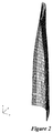
- An isometric 3D graphical view of the whole blade is shown in Figure 2.
- the rotor sections may be "stacked" on a radial line through the centres of gravity of each section, but advantageously the sections are displaced slightly so as to
- Figure 4 is a graphical 3D representation of an isometric view of an example of an LP NGV aerofoil according to the invention. Its profiles at its root, mid-height and tip are as defined in Tables 2A to 2C at the end of this specification.
- Table A compares a known configuration with a configuration according to the invention and shows the enhanced pitch/width ratio achieved for the low pressure nozzle guide vane (LP NGV) and the low pressure rotor.
- LP NGV low pressure nozzle guide vane
- Table A compares a known configuration with a configuration according to the invention and shows the enhanced pitch/width ratio achieved for the low pressure nozzle guide vane (LP NGV) and the low pressure rotor.
- vanes can be indexed circumferentially relative to one another, such that the wakes from HP NGV's fall upon the optimum position in the LP NGV passages (i.e., mid-pitch), thereby to obtain the highest LP stage efficiency. If the wakes from the HP NGV fall upon the leading edges of the LP NGV's then they cause earlier transition of the aerofoil surface boundary layers and higher loss.
- An exhaust design in accordance with the present invention may enable up to a 65% pressure recovery, compared to 60% in the prior art, and the length/height ratio L/H may be reduced to a value in the region of 3 compared to prior art values in the region of 9 to 10. This can considerably reduce the footprint of the overall turbine design, thereby reducing capital costs in the location where the turbine is installed.
- the design philosophy employed in deriving the particular shape illustrated in Figures 3, 5 and 6, involved a process in which each length of exhaust was taken and a series of lip shapes (i.e., turbine exhaust casing profiles), with constant gas velocity, was calculated to find the lip shape that gave the lowest velocity ratio.
- the velocity ratio is a measure of the velocity of the working fluid on the lip compared to the outlet velocity on the last low-pressure stage of the turbine.
- a graphical representation of the flow vectors in the exhaust section shows the blade height H, the line of the LP rotor trailing edge and the diffuser/exhaust length L.
- Flow vectors are shown as broken lines emanating from the trailing edge of the last low pressure stage and terminating in a downstream end wall.
- the parameters defining the shape of the exhaust section are shown in Table 4, where again “x” is the axial distance along the exhaust and “r” is the radial distance from the axis of the turbine.
- xlip and rlip are the x, r co-ordinates of the exhaust casing profile, (i.e., the outer radius of the gas annulus);
- xhub and rhub are the x, r co-ordinates of the gas annulus inner radius; and
- xlip,corr and “xhub,corr” are the axial offset corrections which should be added to the xlip and xhub co-ordinates to match the LP rotor blade discharge flow.
- the co-ordinates are given in millimetres.
- a plot of the (x, r) co-ordinates of the exhaust section is shown in Figure 6,
- the range of values should be understood to be within ⁇ 10% of the nominal data values quoted, preferably ⁇ 5%.
- the x and y dimensions may vary by ⁇ 3mm, preferably ⁇ 1.5mm.
- the permissible variation would be about ⁇ 20mm, preferably about ⁇ 10mm.
- the exemplary embodiment of the invention disclosed in the following Tables and Figures is for a turbine having a power of about 5MW.
- the x-y co-ordinates of Tables 1A to 2C may be multiplied by a predetermined number or scaling factor to achieve similar aerodynamic performance from either larger or smaller vanes and blades.
- the aerofoil section profile shapes and angles described in the Tables may be used for any size gas turbine engine. For example, it may be used in gas turbines with a power output ranging from 5 to 300MW or more.
- the invention is not limited to the particular aerofoil section profile shapes and angles described herein. Because parameters of the present design have been quoted in terms of ratios, the actual sizes of the component parts of a turbine may be scaled without any loss of the significant advantages achievable by the present invention. It is of further importance to note that although aerofoil profiles have been shown and discussed in connection with a particular orientation, the concepts of the present invention are applicable to turbines which have an opposite sense of rotation compared to those illustrated in this particular specification. In other words, the invention is not restricted to any particular handing of the various profiles described. Moreover, blade and/or vane construction can be hollow, thereby making even more weight and therefore cost savings.
Landscapes
- Engineering & Computer Science (AREA)
- Mechanical Engineering (AREA)
- General Engineering & Computer Science (AREA)
- Physics & Mathematics (AREA)
- Fluid Mechanics (AREA)
- Turbine Rotor Nozzle Sealing (AREA)
- Control Of Turbines (AREA)
- Polishing Bodies And Polishing Tools (AREA)
- Supercharger (AREA)
Applications Claiming Priority (2)
| Application Number | Priority Date | Filing Date | Title |
|---|---|---|---|
| GB0201061 | 2002-01-18 | ||
| GB0201061A GB2384276A (en) | 2002-01-18 | 2002-01-18 | Gas turbine low pressure stage |
Publications (3)
| Publication Number | Publication Date |
|---|---|
| EP1331360A2 true EP1331360A2 (fr) | 2003-07-30 |
| EP1331360A3 EP1331360A3 (fr) | 2004-08-18 |
| EP1331360B1 EP1331360B1 (fr) | 2007-05-30 |
Family
ID=9929265
Family Applications (1)
| Application Number | Title | Priority Date | Filing Date |
|---|---|---|---|
| EP03250341A Expired - Lifetime EP1331360B1 (fr) | 2002-01-18 | 2003-01-20 | Disposition des aubes statoriques et rotoriques au niveau de l'échappement d'une turbine |
Country Status (5)
| Country | Link |
|---|---|
| US (1) | US6802695B2 (fr) |
| EP (1) | EP1331360B1 (fr) |
| AT (1) | ATE363584T1 (fr) |
| DE (1) | DE60314024T2 (fr) |
| GB (1) | GB2384276A (fr) |
Cited By (9)
| Publication number | Priority date | Publication date | Assignee | Title |
|---|---|---|---|---|
| EP1840329A1 (fr) * | 2006-03-30 | 2007-10-03 | Snecma | Aube de redresseur optimisée, secteur de redresseurs, étage de compression, compresseur et turbomachine comportant une telle aube |
| WO2007093851A3 (fr) * | 2005-12-29 | 2007-11-29 | Rolls Royce Power Eng | Voilure pour aube directrice de troisieme etage |
| WO2007125382A3 (fr) * | 2005-12-29 | 2008-01-03 | Rolls Royce Power Eng | Profil aérodynamique de turbine de troisième étage |
| US7618240B2 (en) | 2005-12-29 | 2009-11-17 | Rolls-Royce Power Engineering Plc | Airfoil for a first stage nozzle guide vane |
| US7625184B2 (en) | 2005-12-29 | 2009-12-01 | Rolls-Royce Power Engineering Plc | Second stage turbine airfoil |
| US7648340B2 (en) | 2005-12-29 | 2010-01-19 | Rolls-Royce Power Engineering Plc | First stage turbine airfoil |
| US7648334B2 (en) | 2005-12-29 | 2010-01-19 | Rolls-Royce Power Engineering Plc | Airfoil for a second stage nozzle guide vane |
| US20130104550A1 (en) * | 2011-10-28 | 2013-05-02 | General Electric Company | Turbine of a turbomachine |
| EP3032033B1 (fr) | 2014-12-08 | 2021-01-27 | United Technologies Corporation | Ensemble de vanne pour moteur de turbine à gaz |
Families Citing this family (37)
| Publication number | Priority date | Publication date | Assignee | Title |
|---|---|---|---|---|
| US7179058B2 (en) * | 2004-03-21 | 2007-02-20 | Bharat Heavy Electricals Limited | Aerodynamically wide range applicable cylindrical blade profiles |
| US7175393B2 (en) * | 2004-03-31 | 2007-02-13 | Bharat Heavy Electricals Limited | Transonic blade profiles |
| WO2007113149A1 (fr) * | 2006-03-31 | 2007-10-11 | Alstom Technology Ltd | Aube directrice de turbomachine, notamment de turbine à vapeur |
| US7568890B2 (en) * | 2006-11-22 | 2009-08-04 | Pratt & Whitney Canada Corp. | LP turbine vane airfoil profile |
| US7568891B2 (en) * | 2006-11-22 | 2009-08-04 | Pratt & Whitney Canada Corp. | HP turbine vane airfoil profile |
| US8598731B2 (en) * | 2008-08-22 | 2013-12-03 | Natural Power Concepts, Inc. | Rimmed turbine |
| US9291059B2 (en) * | 2009-12-23 | 2016-03-22 | Alstom Technology Ltd. | Airfoil for a compressor blade |
| US8523531B2 (en) * | 2009-12-23 | 2013-09-03 | Alstom Technology Ltd | Airfoil for a compressor blade |
| US8672620B2 (en) * | 2010-08-17 | 2014-03-18 | Hamilton Sundstrand Corporation | Air turbine starter turbine nozzle airfoil |
| US8651806B2 (en) * | 2010-08-17 | 2014-02-18 | Hamilton Sundstrand Corporation | Air turbine starter inlet housing assembly airflow path |
| US8628297B2 (en) * | 2010-08-20 | 2014-01-14 | General Electric Company | Tip flowpath contour |
| US8591184B2 (en) * | 2010-08-20 | 2013-11-26 | General Electric Company | Hub flowpath contour |
| US9309769B2 (en) | 2010-12-28 | 2016-04-12 | Rolls-Royce Corporation | Gas turbine engine airfoil shaped component |
| EP2479381A1 (fr) * | 2011-01-21 | 2012-07-25 | Alstom Technology Ltd | Turbine à flux axial |
| US8864457B2 (en) * | 2011-10-06 | 2014-10-21 | Siemens Energy, Inc. | Gas turbine with optimized airfoil element angles |
| US8967959B2 (en) | 2011-10-28 | 2015-03-03 | General Electric Company | Turbine of a turbomachine |
| US8992179B2 (en) | 2011-10-28 | 2015-03-31 | General Electric Company | Turbine of a turbomachine |
| US9051843B2 (en) | 2011-10-28 | 2015-06-09 | General Electric Company | Turbomachine blade including a squeeler pocket |
| GB201404938D0 (en) * | 2014-03-19 | 2014-04-30 | Rolls Royce Plc | Fluidfoil fence |
| US9869190B2 (en) | 2014-05-30 | 2018-01-16 | General Electric Company | Variable-pitch rotor with remote counterweights |
| EP3186484B1 (fr) | 2014-08-29 | 2019-06-05 | Siemens Aktiengesellschaft | Turbine à gaz |
| US10072510B2 (en) | 2014-11-21 | 2018-09-11 | General Electric Company | Variable pitch fan for gas turbine engine and method of assembling the same |
| US10100653B2 (en) | 2015-10-08 | 2018-10-16 | General Electric Company | Variable pitch fan blade retention system |
| US20170130596A1 (en) * | 2015-11-11 | 2017-05-11 | General Electric Company | System for integrating sections of a turbine |
| US10443393B2 (en) * | 2016-07-13 | 2019-10-15 | Safran Aircraft Engines | Optimized aerodynamic profile for a turbine vane, in particular for a nozzle of the seventh stage of a turbine |
| US10443392B2 (en) * | 2016-07-13 | 2019-10-15 | Safran Aircraft Engines | Optimized aerodynamic profile for a turbine vane, in particular for a nozzle of the second stage of a turbine |
| US10584713B2 (en) | 2018-01-05 | 2020-03-10 | Spectrum Brands, Inc. | Impeller assembly for use in an aquarium filter pump and methods |
| CN109026169A (zh) * | 2018-07-19 | 2018-12-18 | 哈尔滨汽轮机厂有限责任公司 | 一种用于空冷汽轮机的1100mm末级动叶片 |
| PL3816397T3 (pl) * | 2019-10-31 | 2023-06-19 | General Electric Company | Łopatki turbiny o kontrolowanym przepływie |
| CN111636928B (zh) * | 2020-05-29 | 2022-06-21 | 浙江燃创透平机械股份有限公司 | 一种控制反动度分布的高效燃气轮机末级导叶 |
| US11286779B2 (en) | 2020-06-03 | 2022-03-29 | Honeywell International Inc. | Characteristic distribution for rotor blade of booster rotor |
| CN112879102A (zh) * | 2021-04-01 | 2021-06-01 | 哈尔滨汽轮机厂有限责任公司 | 一种用于3000rpm全转速汽轮机的1000mm末级动叶片 |
| US11674435B2 (en) | 2021-06-29 | 2023-06-13 | General Electric Company | Levered counterweight feathering system |
| US11795964B2 (en) | 2021-07-16 | 2023-10-24 | General Electric Company | Levered counterweight feathering system |
| DE102021130522A1 (de) * | 2021-11-22 | 2023-05-25 | MTU Aero Engines AG | Schaufel für eine Strömungsmaschine und Strömungsmaschine, aufweisend zumindest eine Schaufel |
| US12601271B2 (en) | 2022-10-21 | 2026-04-14 | General Electric Company | Variable pitch fan of a gas turbine engine |
| GB202316523D0 (en) * | 2023-10-30 | 2023-12-13 | Rolls Royce Plc | An improved gas turbine engine |
Family Cites Families (17)
| Publication number | Priority date | Publication date | Assignee | Title |
|---|---|---|---|---|
| DE925867C (de) * | 1949-06-10 | 1955-03-31 | Gasturbine Mij N V | Axial durchstroemte Gasturbine |
| CH379837A (de) * | 1959-09-16 | 1964-07-15 | Maschf Augsburg Nuernberg Ag | Schaufelung für axial durchströmte Turbinen, insbesondere Gasturbinen |
| CH541065A (de) * | 1972-01-20 | 1973-08-31 | Bbc Brown Boveri & Cie | Verdrillte Laufschaufel einer axial durchströmten Turbomaschine |
| US4431376A (en) * | 1980-10-27 | 1984-02-14 | United Technologies Corporation | Airfoil shape for arrays of airfoils |
| US4741667A (en) * | 1986-05-28 | 1988-05-03 | United Technologies Corporation | Stator vane |
| US5211703A (en) * | 1990-10-24 | 1993-05-18 | Westinghouse Electric Corp. | Stationary blade design for L-OC row |
| US5203676A (en) * | 1992-03-05 | 1993-04-20 | Westinghouse Electric Corp. | Ruggedized tapered twisted integral shroud blade |
| DE4228879A1 (de) * | 1992-08-29 | 1994-03-03 | Asea Brown Boveri | Axialdurchströmte Turbine |
| US5480285A (en) * | 1993-08-23 | 1996-01-02 | Westinghouse Electric Corporation | Steam turbine blade |
| US5326221A (en) * | 1993-08-27 | 1994-07-05 | General Electric Company | Over-cambered stage design for steam turbines |
| US5352092A (en) * | 1993-11-24 | 1994-10-04 | Westinghouse Electric Corporation | Light weight steam turbine blade |
| GB9417406D0 (en) * | 1994-08-30 | 1994-10-19 | Gec Alsthom Ltd | Turbine blade |
| JP2954539B2 (ja) * | 1996-08-09 | 1999-09-27 | 川崎重工業株式会社 | タンデム翼列 |
| DE59808832D1 (de) * | 1998-09-29 | 2003-07-31 | Alstom Switzerland Ltd | Hochbelastete Turbinenbeschaufelung |
| US6312219B1 (en) * | 1999-11-05 | 2001-11-06 | General Electric Company | Narrow waist vane |
| GB0003676D0 (en) * | 2000-02-17 | 2000-04-05 | Abb Alstom Power Nv | Aerofoils |
| US6398489B1 (en) * | 2001-02-08 | 2002-06-04 | General Electric Company | Airfoil shape for a turbine nozzle |
-
2002
- 2002-01-18 GB GB0201061A patent/GB2384276A/en not_active Withdrawn
-
2003
- 2003-01-20 AT AT03250341T patent/ATE363584T1/de not_active IP Right Cessation
- 2003-01-20 EP EP03250341A patent/EP1331360B1/fr not_active Expired - Lifetime
- 2003-01-20 DE DE60314024T patent/DE60314024T2/de not_active Expired - Lifetime
- 2003-01-21 US US10/348,533 patent/US6802695B2/en not_active Expired - Fee Related
Cited By (22)
| Publication number | Priority date | Publication date | Assignee | Title |
|---|---|---|---|---|
| US7648340B2 (en) | 2005-12-29 | 2010-01-19 | Rolls-Royce Power Engineering Plc | First stage turbine airfoil |
| US7648334B2 (en) | 2005-12-29 | 2010-01-19 | Rolls-Royce Power Engineering Plc | Airfoil for a second stage nozzle guide vane |
| GB2448085B (en) * | 2005-12-29 | 2011-06-08 | Rolls Royce Power Eng | Airfoil for a third stage nozzle guide vane |
| WO2007093851A3 (fr) * | 2005-12-29 | 2007-11-29 | Rolls Royce Power Eng | Voilure pour aube directrice de troisieme etage |
| WO2007125382A3 (fr) * | 2005-12-29 | 2008-01-03 | Rolls Royce Power Eng | Profil aérodynamique de turbine de troisième étage |
| GB2445894A (en) * | 2005-12-29 | 2008-07-23 | Rolls Royce Power Eng | Third stage turbine airfoil |
| GB2448085A (en) * | 2005-12-29 | 2008-10-01 | Rolls Royce Power Eng | Airfoil for a third stage nozzle guide vane |
| US7618240B2 (en) | 2005-12-29 | 2009-11-17 | Rolls-Royce Power Engineering Plc | Airfoil for a first stage nozzle guide vane |
| US7625184B2 (en) | 2005-12-29 | 2009-12-01 | Rolls-Royce Power Engineering Plc | Second stage turbine airfoil |
| US7722329B2 (en) | 2005-12-29 | 2010-05-25 | Rolls-Royce Power Engineering Plc | Airfoil for a third stage nozzle guide vane |
| GB2445894B (en) * | 2005-12-29 | 2011-06-08 | Rolls Royce Power Eng | Third stage turbine airfoil |
| US7632072B2 (en) | 2005-12-29 | 2009-12-15 | Rolls-Royce Power Engineering Plc | Third stage turbine airfoil |
| EP1840329A1 (fr) * | 2006-03-30 | 2007-10-03 | Snecma | Aube de redresseur optimisée, secteur de redresseurs, étage de compression, compresseur et turbomachine comportant une telle aube |
| FR2899269A1 (fr) * | 2006-03-30 | 2007-10-05 | Snecma Sa | Aube de redresseur optimisee, secteur de redresseurs, etage de compression, compresseur et turbomachine comportant une telle aube |
| JP2007270837A (ja) * | 2006-03-30 | 2007-10-18 | Snecma | 最適化された案内羽根、案内羽根の環状体セクタ、そのような羽根を備える圧縮段階、圧縮機およびターボ機械 |
| US20130104550A1 (en) * | 2011-10-28 | 2013-05-02 | General Electric Company | Turbine of a turbomachine |
| CN103089318A (zh) * | 2011-10-28 | 2013-05-08 | 通用电气公司 | 涡轮机的涡轮 |
| EP2586977A3 (fr) * | 2011-10-28 | 2013-07-24 | General Electric Company | Turbine d'une turbomachine |
| CN103089318B (zh) * | 2011-10-28 | 2016-02-03 | 通用电气公司 | 涡轮机的涡轮 |
| US9255480B2 (en) * | 2011-10-28 | 2016-02-09 | General Electric Company | Turbine of a turbomachine |
| EP3032033B1 (fr) | 2014-12-08 | 2021-01-27 | United Technologies Corporation | Ensemble de vanne pour moteur de turbine à gaz |
| EP3032033B2 (fr) † | 2014-12-08 | 2026-01-21 | RTX Corporation | Ensemble de vanne pour moteur de turbine à gaz |
Also Published As
| Publication number | Publication date |
|---|---|
| US20030215330A1 (en) | 2003-11-20 |
| US6802695B2 (en) | 2004-10-12 |
| EP1331360B1 (fr) | 2007-05-30 |
| ATE363584T1 (de) | 2007-06-15 |
| DE60314024D1 (de) | 2007-07-12 |
| DE60314024T2 (de) | 2008-01-24 |
| GB2384276A (en) | 2003-07-23 |
| EP1331360A3 (fr) | 2004-08-18 |
| GB0201061D0 (en) | 2002-03-06 |
Similar Documents
| Publication | Publication Date | Title |
|---|---|---|
| EP1331360B1 (fr) | Disposition des aubes statoriques et rotoriques au niveau de l'échappement d'une turbine | |
| JP6001999B2 (ja) | エーロフォイル、圧縮機、ベーン、ガスタービンエンジン、およびステータの列 | |
| US10408072B2 (en) | Turbine nozzle airfoil profile | |
| US8864457B2 (en) | Gas turbine with optimized airfoil element angles | |
| US10533440B2 (en) | Turbine nozzle airfoil profile | |
| EP3032033B2 (fr) | Ensemble de vanne pour moteur de turbine à gaz | |
| US20110262279A1 (en) | Compressor turbine blade airfoil profile | |
| EP3791047B1 (fr) | Aube directrice de sortie | |
| CN103527260A (zh) | 翼型 | |
| US10415406B2 (en) | Turbine nozzle airfoil profile | |
| KR101370227B1 (ko) | 저압 터빈의 제 1 단용 고정자 | |
| KR101370091B1 (ko) | 저압 터빈의 제 2 단용 고정자 | |
| US9631518B2 (en) | Exhaust diffuser and method for manufacturing an exhaust diffuser | |
| EP3755885B1 (fr) | Étage de turbine avec paroi d'extremité de plateforme profilée et face de contact ondulée | |
| EP2317077A2 (fr) | Ailette optimisée | |
| US10280774B2 (en) | Turbine nozzle airfoil profile | |
| KR101370212B1 (ko) | 저압 터빈의 제 2 단용 로터 | |
| US10837298B2 (en) | First stage turbine nozzle | |
| US11306735B2 (en) | Turbine nozzle airfoil profile | |
| US12270317B2 (en) | Airfoils for gas turbine engines | |
| EP3882436B1 (fr) | Aube rotorique pour une turbomachine et turbomachine associée | |
| KR101370095B1 (ko) | 저압 터빈의 제 1 단용 로터 | |
| US11480056B1 (en) | Airfoil profile for a turbine blade | |
| EP3828390B1 (fr) | Aube statorique de turbomachine avec une surface portante dotée d'un bord de fuite curviligne | |
| US11428159B1 (en) | Airfoil profile for a turbine blade |
Legal Events
| Date | Code | Title | Description |
|---|---|---|---|
| PUAI | Public reference made under article 153(3) epc to a published international application that has entered the european phase |
Free format text: ORIGINAL CODE: 0009012 |
|
| AK | Designated contracting states |
Designated state(s): AT BE BG CH CY CZ DE DK EE ES FI FR GB GR HU IE IT LI LU MC NL PT SE SI SK TR |
|
| AX | Request for extension of the european patent |
Extension state: AL LT LV MK RO |
|
| PUAL | Search report despatched |
Free format text: ORIGINAL CODE: 0009013 |
|
| AK | Designated contracting states |
Kind code of ref document: A3 Designated state(s): AT BE BG CH CY CZ DE DK EE ES FI FR GB GR HU IE IT LI LU MC NL PT SE SI SK TR |
|
| AX | Request for extension of the european patent |
Extension state: AL LT LV MK RO |
|
| 17P | Request for examination filed |
Effective date: 20040906 |
|
| 17Q | First examination report despatched |
Effective date: 20050121 |
|
| AKX | Designation fees paid |
Designated state(s): AT BE BG CH CY CZ DE DK EE ES FI FR GB GR HU IE IT LI LU MC NL PT SE SI SK TR |
|
| RAP1 | Party data changed (applicant data changed or rights of an application transferred) |
Owner name: SIEMENS AKTIENGESELLSCHAFT |
|
| GRAP | Despatch of communication of intention to grant a patent |
Free format text: ORIGINAL CODE: EPIDOSNIGR1 |
|
| GRAS | Grant fee paid |
Free format text: ORIGINAL CODE: EPIDOSNIGR3 |
|
| GRAA | (expected) grant |
Free format text: ORIGINAL CODE: 0009210 |
|
| AK | Designated contracting states |
Kind code of ref document: B1 Designated state(s): AT BE BG CH CY CZ DE DK EE ES FI FR GB GR HU IE IT LI LU MC NL PT SE SI SK TR |
|
| PG25 | Lapsed in a contracting state [announced via postgrant information from national office to epo] |
Ref country code: FI Free format text: LAPSE BECAUSE OF FAILURE TO SUBMIT A TRANSLATION OF THE DESCRIPTION OR TO PAY THE FEE WITHIN THE PRESCRIBED TIME-LIMIT Effective date: 20070530 |
|
| REG | Reference to a national code |
Ref country code: GB Ref legal event code: FG4D |
|
| REG | Reference to a national code |
Ref country code: CH Ref legal event code: EP Ref country code: CH Ref legal event code: NV Representative=s name: SIEMENS SCHWEIZ AG |
|
| REG | Reference to a national code |
Ref country code: IE Ref legal event code: FG4D |
|
| REF | Corresponds to: |
Ref document number: 60314024 Country of ref document: DE Date of ref document: 20070712 Kind code of ref document: P |
|
| PG25 | Lapsed in a contracting state [announced via postgrant information from national office to epo] |
Ref country code: SE Free format text: LAPSE BECAUSE OF FAILURE TO SUBMIT A TRANSLATION OF THE DESCRIPTION OR TO PAY THE FEE WITHIN THE PRESCRIBED TIME-LIMIT Effective date: 20070830 |
|
| PG25 | Lapsed in a contracting state [announced via postgrant information from national office to epo] |
Ref country code: ES Free format text: LAPSE BECAUSE OF FAILURE TO SUBMIT A TRANSLATION OF THE DESCRIPTION OR TO PAY THE FEE WITHIN THE PRESCRIBED TIME-LIMIT Effective date: 20070910 |
|
| ET | Fr: translation filed | ||
| PG25 | Lapsed in a contracting state [announced via postgrant information from national office to epo] |
Ref country code: AT Free format text: LAPSE BECAUSE OF FAILURE TO SUBMIT A TRANSLATION OF THE DESCRIPTION OR TO PAY THE FEE WITHIN THE PRESCRIBED TIME-LIMIT Effective date: 20070530 |
|
| NLV1 | Nl: lapsed or annulled due to failure to fulfill the requirements of art. 29p and 29m of the patents act | ||
| PG25 | Lapsed in a contracting state [announced via postgrant information from national office to epo] |
Ref country code: BE Free format text: LAPSE BECAUSE OF FAILURE TO SUBMIT A TRANSLATION OF THE DESCRIPTION OR TO PAY THE FEE WITHIN THE PRESCRIBED TIME-LIMIT Effective date: 20070530 |
|
| PG25 | Lapsed in a contracting state [announced via postgrant information from national office to epo] |
Ref country code: PT Free format text: LAPSE BECAUSE OF FAILURE TO SUBMIT A TRANSLATION OF THE DESCRIPTION OR TO PAY THE FEE WITHIN THE PRESCRIBED TIME-LIMIT Effective date: 20071030 Ref country code: SI Free format text: LAPSE BECAUSE OF FAILURE TO SUBMIT A TRANSLATION OF THE DESCRIPTION OR TO PAY THE FEE WITHIN THE PRESCRIBED TIME-LIMIT Effective date: 20070530 Ref country code: CZ Free format text: LAPSE BECAUSE OF FAILURE TO SUBMIT A TRANSLATION OF THE DESCRIPTION OR TO PAY THE FEE WITHIN THE PRESCRIBED TIME-LIMIT Effective date: 20070530 Ref country code: BG Free format text: LAPSE BECAUSE OF FAILURE TO SUBMIT A TRANSLATION OF THE DESCRIPTION OR TO PAY THE FEE WITHIN THE PRESCRIBED TIME-LIMIT Effective date: 20070830 Ref country code: DK Free format text: LAPSE BECAUSE OF FAILURE TO SUBMIT A TRANSLATION OF THE DESCRIPTION OR TO PAY THE FEE WITHIN THE PRESCRIBED TIME-LIMIT Effective date: 20070530 Ref country code: NL Free format text: LAPSE BECAUSE OF FAILURE TO SUBMIT A TRANSLATION OF THE DESCRIPTION OR TO PAY THE FEE WITHIN THE PRESCRIBED TIME-LIMIT Effective date: 20070530 |
|
| PG25 | Lapsed in a contracting state [announced via postgrant information from national office to epo] |
Ref country code: SK Free format text: LAPSE BECAUSE OF FAILURE TO SUBMIT A TRANSLATION OF THE DESCRIPTION OR TO PAY THE FEE WITHIN THE PRESCRIBED TIME-LIMIT Effective date: 20070530 |
|
| PLBE | No opposition filed within time limit |
Free format text: ORIGINAL CODE: 0009261 |
|
| STAA | Information on the status of an ep patent application or granted ep patent |
Free format text: STATUS: NO OPPOSITION FILED WITHIN TIME LIMIT |
|
| PG25 | Lapsed in a contracting state [announced via postgrant information from national office to epo] |
Ref country code: GR Free format text: LAPSE BECAUSE OF FAILURE TO SUBMIT A TRANSLATION OF THE DESCRIPTION OR TO PAY THE FEE WITHIN THE PRESCRIBED TIME-LIMIT Effective date: 20070831 |
|
| 26N | No opposition filed |
Effective date: 20080303 |
|
| PGFP | Annual fee paid to national office [announced via postgrant information from national office to epo] |
Ref country code: CH Payment date: 20080415 Year of fee payment: 6 |
|
| PG25 | Lapsed in a contracting state [announced via postgrant information from national office to epo] |
Ref country code: MC Free format text: LAPSE BECAUSE OF NON-PAYMENT OF DUE FEES Effective date: 20080131 |
|
| PG25 | Lapsed in a contracting state [announced via postgrant information from national office to epo] |
Ref country code: IE Free format text: LAPSE BECAUSE OF NON-PAYMENT OF DUE FEES Effective date: 20080121 Ref country code: EE Free format text: LAPSE BECAUSE OF FAILURE TO SUBMIT A TRANSLATION OF THE DESCRIPTION OR TO PAY THE FEE WITHIN THE PRESCRIBED TIME-LIMIT Effective date: 20070530 |
|
| REG | Reference to a national code |
Ref country code: CH Ref legal event code: PCAR Free format text: SIEMENS SCHWEIZ AG;INTELLECTUAL PROPERTY FREILAGERSTRASSE 40;8047 ZUERICH (CH) |
|
| PG25 | Lapsed in a contracting state [announced via postgrant information from national office to epo] |
Ref country code: CY Free format text: LAPSE BECAUSE OF FAILURE TO SUBMIT A TRANSLATION OF THE DESCRIPTION OR TO PAY THE FEE WITHIN THE PRESCRIBED TIME-LIMIT Effective date: 20070530 |
|
| REG | Reference to a national code |
Ref country code: CH Ref legal event code: PL |
|
| PG25 | Lapsed in a contracting state [announced via postgrant information from national office to epo] |
Ref country code: CH Free format text: LAPSE BECAUSE OF NON-PAYMENT OF DUE FEES Effective date: 20090131 Ref country code: LI Free format text: LAPSE BECAUSE OF NON-PAYMENT OF DUE FEES Effective date: 20090131 |
|
| PG25 | Lapsed in a contracting state [announced via postgrant information from national office to epo] |
Ref country code: LU Free format text: LAPSE BECAUSE OF NON-PAYMENT OF DUE FEES Effective date: 20080120 Ref country code: HU Free format text: LAPSE BECAUSE OF FAILURE TO SUBMIT A TRANSLATION OF THE DESCRIPTION OR TO PAY THE FEE WITHIN THE PRESCRIBED TIME-LIMIT Effective date: 20071201 |
|
| PG25 | Lapsed in a contracting state [announced via postgrant information from national office to epo] |
Ref country code: TR Free format text: LAPSE BECAUSE OF FAILURE TO SUBMIT A TRANSLATION OF THE DESCRIPTION OR TO PAY THE FEE WITHIN THE PRESCRIBED TIME-LIMIT Effective date: 20070530 |
|
| REG | Reference to a national code |
Ref country code: FR Ref legal event code: PLFP Year of fee payment: 13 |
|
| PGFP | Annual fee paid to national office [announced via postgrant information from national office to epo] |
Ref country code: IT Payment date: 20150128 Year of fee payment: 13 Ref country code: DE Payment date: 20150320 Year of fee payment: 13 |
|
| PGFP | Annual fee paid to national office [announced via postgrant information from national office to epo] |
Ref country code: FR Payment date: 20150114 Year of fee payment: 13 Ref country code: GB Payment date: 20150114 Year of fee payment: 13 |
|
| REG | Reference to a national code |
Ref country code: DE Ref legal event code: R119 Ref document number: 60314024 Country of ref document: DE |
|
| GBPC | Gb: european patent ceased through non-payment of renewal fee |
Effective date: 20160120 |
|
| REG | Reference to a national code |
Ref country code: FR Ref legal event code: ST Effective date: 20160930 |
|
| PG25 | Lapsed in a contracting state [announced via postgrant information from national office to epo] |
Ref country code: DE Free format text: LAPSE BECAUSE OF NON-PAYMENT OF DUE FEES Effective date: 20160802 Ref country code: GB Free format text: LAPSE BECAUSE OF NON-PAYMENT OF DUE FEES Effective date: 20160120 |
|
| PG25 | Lapsed in a contracting state [announced via postgrant information from national office to epo] |
Ref country code: FR Free format text: LAPSE BECAUSE OF NON-PAYMENT OF DUE FEES Effective date: 20160201 |
|
| PG25 | Lapsed in a contracting state [announced via postgrant information from national office to epo] |
Ref country code: IT Free format text: LAPSE BECAUSE OF NON-PAYMENT OF DUE FEES Effective date: 20160120 |