EP1332923B1 - Dispositif d'aide à la manoeuvre et au stationnement d'un véhicule - Google Patents
Dispositif d'aide à la manoeuvre et au stationnement d'un véhicule Download PDFInfo
- Publication number
- EP1332923B1 EP1332923B1 EP02027831A EP02027831A EP1332923B1 EP 1332923 B1 EP1332923 B1 EP 1332923B1 EP 02027831 A EP02027831 A EP 02027831A EP 02027831 A EP02027831 A EP 02027831A EP 1332923 B1 EP1332923 B1 EP 1332923B1
- Authority
- EP
- European Patent Office
- Prior art keywords
- image acquisition
- acquisition unit
- cover
- vehicle
- protective element
- Prior art date
- Legal status (The legal status is an assumption and is not a legal conclusion. Google has not performed a legal analysis and makes no representation as to the accuracy of the status listed.)
- Expired - Lifetime
Links
Images


Classifications
-
- B—PERFORMING OPERATIONS; TRANSPORTING
- B60—VEHICLES IN GENERAL
- B60R—VEHICLES, VEHICLE FITTINGS, OR VEHICLE PARTS, NOT OTHERWISE PROVIDED FOR
- B60R11/00—Arrangements for holding or mounting articles, not otherwise provided for
- B60R11/04—Mounting of cameras operative during drive; Arrangement of controls thereof relative to the vehicle
-
- B—PERFORMING OPERATIONS; TRANSPORTING
- B60—VEHICLES IN GENERAL
- B60S—SERVICING, CLEANING, REPAIRING, SUPPORTING, LIFTING, OR MANOEUVRING OF VEHICLES, NOT OTHERWISE PROVIDED FOR
- B60S1/00—Cleaning of vehicles
- B60S1/02—Cleaning windscreens, windows or optical devices
- B60S1/56—Cleaning windscreens, windows or optical devices specially adapted for cleaning other parts or devices than front windows or windscreens
- B60S1/566—Cleaning windscreens, windows or optical devices specially adapted for cleaning other parts or devices than front windows or windscreens including wiping devices
Definitions
- the invention relates to a parking and / or Rangier ashamed worn for cars or trucks according to the preamble of claim 1.
- the observation of, for example, the rear space behind a vehicle is essential.
- the mirrors in the rearward area will form so-called blind spots which the driver can not see.
- image acquisition units for example video cameras whose images are displayed on an image display unit arranged in the vehicle interior
- the areas not visible to the conventional mirror can also be displayed to the driver in such a way that he has a substantially complete overview of basically any observation area
- Image information forwarded unprocessed and displayed for example as a simple television picture.
- systems are also known for processing the image information recorded by the image acquisition unit, by means of which it is possible to display to the driver the vehicle with the environment from a bird's-eye view as a schematic image.
- a vehicle camera which is rotatably mounted in a protective housing.
- a drive mechanism is provided with different drive shafts.
- Object of the present invention is to propose a new parking and / or Rangier Anlagen thanks to
- the image capture unit is arranged from the outside substantially inaccessible behind a protective element.
- This protective element can be formed, for example, from parts of the vehicle body, in particular from the boot lid, so that no additional effort is required for the protective element itself.
- a recess In the protective element is generically provided a recess. This recess serves to allow the predetermined observation area to be recorded by the image acquisition unit.
- the image acquisition unit is mounted adjustably behind the protective element and can be adjusted by means of a drive device between the rest position and at least one different operating position.
- This makes it possible, in particular, for the image-capturing unit to be moved so far forward when the operating position is approached that at least parts of the image-capturing unit pass through the recess to a certain extent.
- This makes it possible, for example, to drive the camera lens of a video camera so far forward that the viewing angle is no longer limited by the protective element and thus can be recorded depending on the lens properties, for example when using a wide-angle lens, very large observation areas.
- the drive device for producing the image acquisition unit is designed in the manner of a bimetallic unit.
- the recess is closed in the protective element with a transparent cover. This makes it possible, in particular, to form a space which is essentially closed off from the outside, in which the image acquisition unit is then arranged. As far as the cover is attached behind the recess, the image capture unit can not be adjusted through the recess in this case.
- a condensation film can form on the cover element, which impairs the transparency properties. It is therefore particularly advantageous if the cover can be heated, so that, in accordance with the function of heated rear discs, defrosting is possible.
- This function can be ensured in a simple manner, for example, by forming the cover element in the manner of a conductive coated glass pane. By applying a suitable supply voltage to such coated glass panes, heating of the pane surface is made possible.
- the visual design of the vehicle is of paramount importance. If the generic protective element for protecting the image acquisition unit is formed, for example, by a part of the vehicle body of the vehicle, the appearance of the body can be impaired by this additional functional element. Because the image capture unit only in very specific driving situations is used and is in most driving situations out of action, it is proposed to improve the vehicle optics for these cases to provide on the outside of the protective element an adjustable lid, which can be adjusted by means of the bimetallic unit between a rest position and a different operating position. In the rest position, the recess in the protective element is substantially completely covered by the cover, so that the recess with the image capture unit behind it is no longer visible from the outside.
- the lid Only by moving the lid into the operating position, the recess is released, so that either image capturing through the recess are possible or the image capture unit can be adjusted through the recess to the outside.
- the lid also ensures additional protection of the image acquisition unit against contamination and damage.
- the image acquisition unit to be driven through the recess to the front, then the opening of the lid and the forward driving of the camera is required to produce the operational readiness of the parking and / or Rangier Anlagen combined. It is therefore particularly advantageous to provide only a common bimetallic unit in such trained systems for driving both the image capture unit and the lid. Between the bimetallic unit and the lid on the one hand or the image acquisition unit on the other hand transmission elements, such as push rods or transmission gear are then provided so that when driving the drive device simultaneously opens the lid and the image acquisition unit is moved forward.
- the lid according to a preferred embodiment in the manner of a manufacturer emblem, a nameplate or the like formed, so differ the appearance of a vehicle that with a parking and / or Rangier Vietnamese in question here is equipped, and a vehicle without such a parking and / or Rangier Vietnamese noise not at all. Only upon activation of the parking and / or Rangier Vietnamese and the associated opening of the lid, the recess in the protective element with the underlying image acquisition unit is visible.
- the lid is rotatably mounted in a rotation axis which is arranged eccentrically with respect to the center of the lid and extends substantially perpendicular to the body plane of the lid.
- the lid is rotated about this axis of rotation, wherein the lid is moved in each case in his body plane and thus in all operating situations with its inside on the outside of the protective element directly or indirectly.
- a parallel to the outside of the protective element directed wiping movement is performed by the lid when opening the lid. If cleaning elements are provided on the side of the cover facing the image acquisition unit, a cleaning of, for example, the camera lens or another transparent cover element can be effected by the corresponding wiping movement when opening or closing the cover.
- sealing elements for example sealing lips, are provided on the side of the cover facing the image acquisition unit.
- the lid can be locked in the rest position with a locking element.
- locking elements are known, for example, for locking the fuel filler flap.
- the parking and / or Rangier Anlagen can be used effectively even in darkness, it is particularly advantageous if the image capture unit is associated with a lighting device. Either with each activation of the image acquisition unit or only when falling below a predetermined brightness level, the observation area outside the vehicle can then be illuminated with the illumination device, so that sufficiently contour-sharp image recordings are possible.
- the generic protective element can be formed by any component on the vehicle, which offers sufficient mechanical strength to protect the image capture device. It is particularly advantageous if the protective element is formed by a part of the vehicle bodywork, in particular by the trunk lid, since the components of the vehicle bodywork are to be provided anyway in the production of the vehicle and, moreover, due to their function as a vehicle body, readily provide sufficient mechanical stability.
- the arrangement in the boot lid is particularly advantageous, since the area behind the rear of the vehicle can be substantially completely accommodated with the image capture unit.
- nameplates or manufacturer emblems are often provided on the boot lid, so that the cover of the recess for the image acquisition unit is made possible in a visually appealing manner.
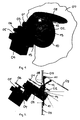
- the image capture device 01 shown schematically in FIG. 1 is designed as an electronic video camera with a CCD chip and has a wide-angle lens 02 which is shown only schematically.
- the image acquisition unit 01 is mounted on a carriage 03, which is mounted linearly displaceable on a bearing block 04.
- the bearing block 04 is fastened in the interior of a vehicle trunk to fasteners, not shown in FIG. 1.
- an electric geared motor 05 with drive disk 06 is provided on the upper side of the bearing block 04.
- the drive pulley 06 is in engagement with the carriage 01, so that the carriage 03 can be pushed or pulled forwards or backwards by a corresponding drive movement of the geared motor 05.
- a protective element 07 which is formed from the plate of the boot lid, arranged.
- a recess 08 is provided in the protective element 07.
- a cover 09 is provided on the outside of the protective element 07, which is pivotally mounted on a mounting plate 10 about a pivot axis 11.
- the mounting plate 10 in turn is mounted in the region of the recess 08 from the outside on the protective element 07, for example, with screws or attached by an adhesive layer.
- the cover 09 is connected by a push rod 12 with the image capture unit 01.
- FIG. 2 shows the image acquisition unit 01 in the activated state.
- the image acquisition unit 01 with the objective 02 passes through the recess 08 in the protection element 07, so that the observation region lying outside the vehicle can be optimally recorded.
- two illumination devices 13 are provided in the mounting plate with which the area behind the rear of the vehicle can be illuminated.
- the geared motor 05 is driven in such a way that the carriage 03 is retracted so far together with the image acquisition unit 01 that the objective 02 no longer projects beyond the recess 08 to the outside.
- the push rod 12 is also pulled inwards, so that the cover 09 closes over the recess 08.
- the cover 09 is then straight close to the mounting plate 10, so that the recess 08 is sealed to the outside.
- FIGS. 3 to 6 show a second embodiment 14 of an image acquisition unit for use for a parking assistance device.
- the image capture unit 14 has a camera mount 15 which can be fixedly mounted in the vehicle and which is fastened, for example, on the inside of a boot lid behind a suitable recess in the boot lid.
- a camera 16 mounted in the camera holder 15 is fixedly mounted in the vehicle.
- the cover 19 is pivotably mounted on a carriage 20.
- the camera holder 15 is shown broken in Fig. 4 .
- the cover 20 is slidably mounted with guide rails 21 in the camera holder 15.
- a spring element not shown, is provided which presses the lid 19 in the closed position down.
- the cover 20 can thereby be opened by hand in the closed position by overcoming the spring force.
- the drive unit 18 essentially consists of an electric motor 22, which acts on a rack 23 via a gear.
- the rack 23 is connected to the carriage 20, so that as a result by driving the electric motor 22, the carriage 20 can be moved linearly.
- the function of the image acquisition unit 14 becomes clear from FIGS. 5 and 6 .
- the drive unit 18 is started and pulls the carriage 20 by means of the rack 23 inwards.
- the cover 19 is thereby pivoted upward by the system at the top edge of the camera against the spring force and releases the camera lens 17, so that the field of view for the camera 16 is released.
- the shutdown of the drive unit 18 in the end position can be done via limit switch or shutdown upon detection of a current increase.
- the front edge 24 protrudes a little way and thereby forms a protection of the camera lens against falling water droplets.
- FIG. 7 shows an adjusting device 25 suitable for fastening an image acquisition unit in a view from above.
- Such an adjusting device 25 can be arranged, for example, between the camera holder 15 and the camera 16 in order to be able to adjust the camera 16 in the correct position after mounting the camera holder 15 on the vehicle.
- a base plate 26 and an attached attachment means 27 is provided at the adjusting device 25.
- the mounting device 27 is used to attach a camera to the adjusting device 25.
- the base plate 27 can be fixed, for example, in three points to a suitable support structure.
- a deformation element 28 is provided which is deformable when adjusting the base plate 27.
- two adjusting screws 29 and 30 are provided in order to adjust the base plate together with the attached camera vertically and horizontally. By turning the adjusting screws 29 and 30, the camera, which is attached to the adjusting device 25, can be pivoted in the horizontal and vertical directions.
Landscapes
- Engineering & Computer Science (AREA)
- Mechanical Engineering (AREA)
- Fittings On The Vehicle Exterior For Carrying Loads, And Devices For Holding Or Mounting Articles (AREA)
- Closed-Circuit Television Systems (AREA)
- Studio Devices (AREA)
Claims (19)
- - Dispositif d'aide à la manoeuvre et/ou au stationnement d'un véhicule poids lourd ou léger comprenant une unité de prise d'images (01), par exemple une caméra vidéo et une unité de formation d'image, avec laquelle les informations d'image saisies par l'unité de prise d'image (01) peuvent être affichées de façon traitée et/ou non traitée dans l'espace intérieur du véhicule, dans lequel l'unité de prise d'images (01) est au moins dans une position de repos, disposée derrière un élément de protection (07) de façon à être sensiblement inaccessible, un évidement (08) correspondant à l'unité de prise d'image (01) étant prévu dans l'élément de protection (07) et l'unité de prise d'image (01) étant disposée de façon déplaçable au moyen d'un dispositif d'entraînement (05) entre la position de repos et au moins une position de service différente de cette dernière, caractérisé en ce que le dispositif d'entraînement est réalisé sous la forme d'une unité du type bimétal.
- - Dispositif selon la revendication 1, caractérisé en ce que l'unité de prise d'images (01) est disposée sur un traîneau (03) qui peut être déplacé linéairement par rapport à l'élément de protection (07).
- - Dispositif selon la revendication 1 ou 2, caractérisé en ce que dans au moins une position de service, l'unité de prise d'images (01) fait saillie au moins partiellement de l'évidement (08) de l'élément de protection (07).
- - Dispositif selon l'une des revendications 1 à 3, caractérisé en ce que l'évidement réalisé en particulier par un espace sensiblement fermé vers l'extérieur, est obturé par un élément de couverture transparent.
- - Dispositif selon la revendication 4, caractérisé en ce que l'élément de couverture peut être chauffé.
- - Dispositif selon l'une des revendications 1 à 5, caractérisé en ce que l'élément de couverture est réalisé en particulier sous la forme d'une plaque en verre revêtue d'une couche conductrice.
- - Dispositif selon l'une des revendications 1 à 6, caractérisé en ce qu'un couvercle (09) monté de façon mobile est prévu sur la face extérieure de l'élément de protection (07), ce couvercle étant déplaçable au moyen de l'unité de bimétal entre une position de repos dans laquelle l'évidement (08) de l'élément de protection (07) est sensiblement complètement recouvert par le couvercle (09) et au moins une position de service différente de cette dernière dans laquelle il est possible de prendre des images de la zone d'observation située à l'extérieur du véhicule au moyen de l'unité de prise d'images disposée derrière l'élément de protection à travers l'évidement ou dans laquelle l'unité de prise d'images (01) fait au moins saillie partiellement de l'évidement (08) de l'élément de protection (07).
- - Dispositif selon la revendication 7, caractérisé en ce que pour l'entraînement de l'unité de prise d'images (01) montée de façon déplaçable et du couvercle (09) monté de façon mobile, une unité commune de bimétal est utilisée, dont les mouvements d'entraînement sont transmis par des éléments de transmission (06, 12) qui relient ensemble ou séparément le couvercle (09) et l'unité de prise d'images (01) à l'unité de bimétal.
- - Dispositif selon la revendication 7 ou 8, caractérisé en ce que le couvercle (09) est réalisé sous forme d'un emblème de fabricant ou d'une étiquette de type.
- - Dispositif selon l'une des revendications 7 à 9, caractérisé en ce que le couvercle (09) est monté pivotant autour d'un axe de pivotement (11) entre une position de repos et une position de service.
- - Dispositif selon l'une des revendications 7 à 9, caractérisé en ce que le couvercle peut être pivoté dans le plan de son corps autour d'un axe de pivotement entre une position de repos et une position de service, l'axe de pivotement étant situé de façon excentrée par rapport au milieu du couvercle et s'étendant de façon sensiblement perpendiculaire au plan du corps du couvercle.
- - Dispositif selon l'une de revendications 7 à 11, caractérisé en de que sur le côté du couvercle dirigé vers l'unité de prise d'images sont prévus des éléments de nettoyage.
- - Dispositif selon l'une des revendications 7 à 12, caractérisé en ce que sur le côté du couvercle dirigé vers l'unité de prise d'images sont prévus des éléments d'étanchéité, en particulier des lèvres d'étanchéité.
- - Dispositif selon l'une des revendications 7 à 13, caractérisé en ce que le couvercle peut être verrouillé dans sa position de repos par un élément de verrouillage.
- - Dispositif selon l'une des revendications 1 à 14, caractérisé en ce que l'unité de prise d'images (01) montée de façon déplaçable et/ou le couvercle (09) monté de façon mobile peuvent être commandés par actionnement d'un élément de commutation et/ou par passage de la marche arrière de façon à déplacer l'unité de prise d'images (01) et/ou le couvercle (09) entre la position de repos et la position de service et inversement.
- - Dispositif selon l'une des revendications 1 à 15, caractérisé en ce qu'un dispositif d'éclairage (13) est associé à l'unité de prise d'images (01) pour éclairer au moins partiellement la zone d'observation à l'extérieur du véhicule.
- - Dispositif selon l'une des revendications 1 à 16, caractérisé en ce que l'élément de protection (07) est réalisé par une partie de la carrosserie du véhicule, en particulier par le couvercle du coffre.
- - Dispositif selon l'une des revendications 1 à 17, caractérisé en ce que l'unité de formation d'image est réalisée sous la forme d'un écran d'affichage sur lequel peuvent également être affichées, au choix, des données et/ou des images d'un système de navigation.
- - Dispositif selon l'une des revendications 1 à 18, caractérisé en ce que l'unité de prise d'images est montée sur un système d'ajustage pouvant être aligné horizontalement et/ou verticalement.
Applications Claiming Priority (4)
| Application Number | Priority Date | Filing Date | Title |
|---|---|---|---|
| DE2002104764 DE10204764A1 (de) | 2002-02-05 | 2002-02-05 | Einpark- und/oder Rangierhilfeeinrichtung |
| DE10204764 | 2002-02-05 | ||
| DE10247056 | 2002-10-09 | ||
| DE10247056 | 2002-10-09 |
Publications (3)
| Publication Number | Publication Date |
|---|---|
| EP1332923A2 EP1332923A2 (fr) | 2003-08-06 |
| EP1332923A3 EP1332923A3 (fr) | 2004-12-01 |
| EP1332923B1 true EP1332923B1 (fr) | 2007-07-11 |
Family
ID=26011002
Family Applications (1)
| Application Number | Title | Priority Date | Filing Date |
|---|---|---|---|
| EP02027831A Expired - Lifetime EP1332923B1 (fr) | 2002-02-05 | 2002-12-12 | Dispositif d'aide à la manoeuvre et au stationnement d'un véhicule |
Country Status (3)
| Country | Link |
|---|---|
| US (1) | US6819231B2 (fr) |
| EP (1) | EP1332923B1 (fr) |
| DE (1) | DE50210454D1 (fr) |
Cited By (3)
| Publication number | Priority date | Publication date | Assignee | Title |
|---|---|---|---|---|
| EP2054572B2 (fr) † | 2006-08-22 | 2014-01-22 | Huf Hülsbeck & Fürst GmbH & Co. KG | Dispositif pour ouvrir une serrure de véhicule automobile et pour la prise d'image dans la zone externe du véhicule |
| CN108833750A (zh) * | 2018-06-20 | 2018-11-16 | 安徽恒泰机械股份有限公司 | 一种应用于新能源汽车后视摄像头的保护结构 |
| US10576906B2 (en) | 2015-01-23 | 2020-03-03 | Witte Automotive Gmbh | Camera arrangement |
Families Citing this family (181)
| Publication number | Priority date | Publication date | Assignee | Title |
|---|---|---|---|---|
| US5910854A (en) | 1993-02-26 | 1999-06-08 | Donnelly Corporation | Electrochromic polymeric solid films, manufacturing electrochromic devices using such solid films, and processes for making such solid films and devices |
| US6822563B2 (en) | 1997-09-22 | 2004-11-23 | Donnelly Corporation | Vehicle imaging system with accessory control |
| US5877897A (en) | 1993-02-26 | 1999-03-02 | Donnelly Corporation | Automatic rearview mirror, vehicle lighting control and vehicle interior monitoring system using a photosensor array |
| US5668663A (en) | 1994-05-05 | 1997-09-16 | Donnelly Corporation | Electrochromic mirrors and devices |
| US6891563B2 (en) | 1996-05-22 | 2005-05-10 | Donnelly Corporation | Vehicular vision system |
| US7655894B2 (en) | 1996-03-25 | 2010-02-02 | Donnelly Corporation | Vehicular image sensing system |
| US6326613B1 (en) | 1998-01-07 | 2001-12-04 | Donnelly Corporation | Vehicle interior mirror assembly adapted for containing a rain sensor |
| US6172613B1 (en) | 1998-02-18 | 2001-01-09 | Donnelly Corporation | Rearview mirror assembly incorporating vehicle information display |
| US8294975B2 (en) | 1997-08-25 | 2012-10-23 | Donnelly Corporation | Automotive rearview mirror assembly |
| US6124886A (en) | 1997-08-25 | 2000-09-26 | Donnelly Corporation | Modular rearview mirror assembly |
| US6445287B1 (en) | 2000-02-28 | 2002-09-03 | Donnelly Corporation | Tire inflation assistance monitoring system |
| US8288711B2 (en) | 1998-01-07 | 2012-10-16 | Donnelly Corporation | Interior rearview mirror system with forwardly-viewing camera and a control |
| US6329925B1 (en) | 1999-11-24 | 2001-12-11 | Donnelly Corporation | Rearview mirror assembly with added feature modular display |
| US6693517B2 (en) | 2000-04-21 | 2004-02-17 | Donnelly Corporation | Vehicle mirror assembly communicating wirelessly with vehicle accessories and occupants |
| US6477464B2 (en) | 2000-03-09 | 2002-11-05 | Donnelly Corporation | Complete mirror-based global-positioning system (GPS) navigation solution |
| US7366595B1 (en) * | 1999-06-25 | 2008-04-29 | Seiko Epson Corporation | Vehicle drive assist system |
| AU2001243285A1 (en) | 2000-03-02 | 2001-09-12 | Donnelly Corporation | Video mirror systems incorporating an accessory module |
| US7370983B2 (en) | 2000-03-02 | 2008-05-13 | Donnelly Corporation | Interior mirror assembly with display |
| US7167796B2 (en) | 2000-03-09 | 2007-01-23 | Donnelly Corporation | Vehicle navigation system for use with a telematics system |
| US7581859B2 (en) | 2005-09-14 | 2009-09-01 | Donnelly Corp. | Display device for exterior rearview mirror |
| WO2002062623A2 (fr) | 2001-01-23 | 2002-08-15 | Donnelly Corporation | Systeme d'eclairage ameliore destine a un vehicule |
| US7255451B2 (en) | 2002-09-20 | 2007-08-14 | Donnelly Corporation | Electro-optic mirror cell |
| KR200277875Y1 (ko) * | 2002-03-11 | 2002-06-14 | 이스턴 마스텍 주식회사 | 자동차의 후방용 감시카메라의 좌우반전 스위칭 장치 |
| AU2003225228A1 (en) | 2002-05-03 | 2003-11-17 | Donnelly Corporation | Object detection system for vehicle |
| US6918674B2 (en) | 2002-05-03 | 2005-07-19 | Donnelly Corporation | Vehicle rearview mirror system |
| US7329013B2 (en) | 2002-06-06 | 2008-02-12 | Donnelly Corporation | Interior rearview mirror system with compass |
| AU2003237424A1 (en) | 2002-06-06 | 2003-12-22 | Donnelly Corporation | Interior rearview mirror system with compass |
| WO2004103772A2 (fr) | 2003-05-19 | 2004-12-02 | Donnelly Corporation | Assemblage de retroviseur pour vehicule |
| AU2003278863A1 (en) | 2002-09-20 | 2004-04-08 | Donnelly Corporation | Mirror reflective element assembly |
| US7310177B2 (en) | 2002-09-20 | 2007-12-18 | Donnelly Corporation | Electro-optic reflective element assembly |
| FR2858280B1 (fr) * | 2003-07-29 | 2008-12-26 | Valeo Systemes Dessuyage | Dispositif de vision arriere pour vehicule automobile |
| US7446924B2 (en) | 2003-10-02 | 2008-11-04 | Donnelly Corporation | Mirror reflective element assembly including electronic component |
| US7308341B2 (en) | 2003-10-14 | 2007-12-11 | Donnelly Corporation | Vehicle communication system |
| JP2005145217A (ja) * | 2003-11-14 | 2005-06-09 | Auto Network Gijutsu Kenkyusho:Kk | 車載表示装置及び車両周辺監視装置 |
| US7526103B2 (en) | 2004-04-15 | 2009-04-28 | Donnelly Corporation | Imaging system for vehicle |
| US7881496B2 (en) | 2004-09-30 | 2011-02-01 | Donnelly Corporation | Vision system for vehicle |
| JP2006168639A (ja) * | 2004-12-17 | 2006-06-29 | Niles Co Ltd | 車両用撮像装置 |
| US7230523B2 (en) * | 2005-01-07 | 2007-06-12 | Delphi Technologies, Inc. | Vehicular rear view mirror/video display |
| USD559881S1 (en) * | 2005-04-22 | 2008-01-15 | Autonetworks Technologies, Ltd | Surveillance camera for an automobile |
| ATE517368T1 (de) | 2005-05-16 | 2011-08-15 | Donnelly Corp | Fahrzeugspiegelanordnung mit zeichen am reflektierenden teil |
| JP2006321273A (ja) * | 2005-05-17 | 2006-11-30 | Denso Corp | 車載撮影システム |
| FR2885860B1 (fr) * | 2005-05-20 | 2007-08-17 | Valeo Vision Sa | Dispositif de detection d'obstacles comportant un systeme d'imagerie pour vehicule automobile |
| JP4349350B2 (ja) | 2005-09-05 | 2009-10-21 | トヨタ自動車株式会社 | 顔画像撮影カメラの搭載構造 |
| USD553660S1 (en) * | 2005-09-27 | 2007-10-23 | Autonetworks Technologies, Ltd. | Surveillance camera for an automobile |
| CN101535087B (zh) | 2005-11-01 | 2013-05-15 | 唐纳利公司 | 具有显示装置的内部后视镜 |
| US7283042B1 (en) | 2005-11-14 | 2007-10-16 | Cawley Fred R | System for observing the area laterally behind a vehicle |
| DE102005062737A1 (de) * | 2005-12-22 | 2007-07-05 | Cuma Kilic | Überwachungseinrichtung für Kraftfahrzeuge |
| EP1814001B1 (fr) * | 2006-01-11 | 2015-09-16 | Siemens Aktiengesellschaft | Appareil d'automatisation et procédé d'opération d'un appareil d'automatisation |
| US8194132B2 (en) | 2006-01-20 | 2012-06-05 | Old World Industries, Llc | System for monitoring an area adjacent a vehicle |
| ATE509296T1 (de) | 2006-03-09 | 2011-05-15 | Gentex Corp | Fahrzeugrückspiegelanordnung mit anzeige von hoher intensität |
| US7511607B2 (en) * | 2006-03-28 | 2009-03-31 | D. Larry Hubbard | Vehicle back-up viewing system |
| JP4742953B2 (ja) * | 2006-03-31 | 2011-08-10 | 株式会社デンソー | 画像処理装置,画像表示システムおよびプログラム |
| US7567167B2 (en) | 2006-04-24 | 2009-07-28 | Reverse Control, Inc. | Wireless signal apparatus for assisting drivers to back large vehicles |
| DE102006023103A1 (de) | 2006-05-16 | 2007-11-22 | Huf Hülsbeck & Fürst Gmbh & Co. Kg | Vorrichtung zur Bilderfassung des Außenbereichs von einem Fahrzeug mittels einer Kamera |
| WO2008024639A2 (fr) | 2006-08-11 | 2008-02-28 | Donnelly Corporation | Système de commande automatique de phare de véhicule |
| DE102006048373A1 (de) * | 2006-10-09 | 2008-04-10 | Huf Hülsbeck & Fürst Gmbh & Co. Kg | Vorrichtung für ein Kraftfahrzeug mit einer drehbar gelagerten Kameraeinheit |
| USD575318S1 (en) * | 2007-02-27 | 2008-08-19 | Zorg Industries, Pty Ltd. | Vehicle camera frame |
| US20090051514A1 (en) * | 2007-08-24 | 2009-02-26 | University Of Kuwait | Car Collision Global Positioning System |
| US7714704B1 (en) * | 2007-08-24 | 2010-05-11 | Joshua Mellen | Removable video safety system for a moving vehicle |
| US8218007B2 (en) | 2007-09-23 | 2012-07-10 | Volkswagen Ag | Camera system for a vehicle and method for controlling a camera system |
| DE102007052401B4 (de) | 2007-10-31 | 2019-01-24 | Huf Hülsbeck & Fürst Gmbh & Co. Kg | Vorrichtung mit einer Kameraeinheit |
| DE102007052402B4 (de) * | 2007-10-31 | 2020-12-17 | Huf Hülsbeck & Fürst Gmbh & Co. Kg | Vorrichtung mit einer Kameraeinheit und Verfahren zum Betrieb einer solchen Vorrichtung |
| US8013720B2 (en) * | 2007-11-02 | 2011-09-06 | Reverse Control, Inc. | Signal apparatus for facilitating safe backup of vehicles |
| DE102008008656A1 (de) * | 2008-02-11 | 2009-08-13 | Huf Hülsbeck & Fürst Gmbh & Co. Kg | Kamerasystem für ein Kraftfahrzeug mit einer Kameraeinheit |
| US8154418B2 (en) | 2008-03-31 | 2012-04-10 | Magna Mirrors Of America, Inc. | Interior rearview mirror system |
| US8572895B2 (en) * | 2008-07-29 | 2013-11-05 | GM Global Technology Operations LLC | Receiver/emitter cover utilizing active material actuation |
| DE102008059918A1 (de) * | 2008-09-09 | 2010-03-11 | Huf Hülsbeck & Fürst Gmbh & Co. Kg | Montagemodul |
| DE102008046453A1 (de) * | 2008-09-09 | 2010-03-11 | Huf Hülsbeck & Fürst Gmbh & Co. Kg | Modulare Bilderfassungseinheit |
| US9487144B2 (en) | 2008-10-16 | 2016-11-08 | Magna Mirrors Of America, Inc. | Interior mirror assembly with display |
| EP2179892A1 (fr) | 2008-10-24 | 2010-04-28 | Magna Electronics Europe GmbH & Co. KG | Procédé de calibrage automatique d'une caméra virtuelle |
| WO2010099416A1 (fr) | 2009-02-27 | 2010-09-02 | Magna Electronics | Système d'alerte pour véhicule |
| US20100289631A1 (en) * | 2009-05-12 | 2010-11-18 | Ford Global Technologies, Llc | Dual-mode vehicle rear vision system |
| US8376595B2 (en) | 2009-05-15 | 2013-02-19 | Magna Electronics, Inc. | Automatic headlamp control |
| US20110102583A1 (en) * | 2009-10-30 | 2011-05-05 | Kim Kinzalow | Rear view camera system and calibration method |
| DE102009060425B4 (de) * | 2009-12-22 | 2021-06-24 | Huf Hülsbeck & Fürst Gmbh & Co. Kg | Kameraeinrichtung zur Bilderfassung eines Außenbereichs an einem Fahrzeug |
| DE102010001108A1 (de) * | 2010-01-15 | 2011-07-21 | Huf Hülsbeck & Fürst GmbH & Co. KG, 42551 | Vorrichtung für ein Kraftfahrzeug mit einer bewegbar gelagerten Kameraeinheit sowie Kraftfahrzeug |
| DE102010001196A1 (de) | 2010-01-15 | 2011-07-21 | Huf Hülsbeck & Fürst GmbH & Co. KG, 42551 | Vereinfachte Vorrichtung einer Kameraeinheit eines Kraftfahrzeugs |
| EP2580622B1 (fr) * | 2010-06-11 | 2018-01-03 | Huf Hülsbeck & Fürst GmbH & Co. KG | Dispositif avec une unité de caméra pour véhicule automobile |
| EP2418123B1 (fr) * | 2010-08-11 | 2012-10-24 | Valeo Schalter und Sensoren GmbH | Procédé et système d'aide du conducteur d'un véhicule aux manýuvres du véhicule lors d'un itinéraire et dispositif de communication portable |
| DE102010045214A1 (de) * | 2010-09-13 | 2012-03-15 | Audi Ag | Kameraanordnung für ein Fahrzeug und Verfahren zum Einbau einer Kameraanordnung in ein Fahrzeug |
| DE112011103834B4 (de) | 2010-11-19 | 2026-03-26 | Magna Electronics, Inc. | Spurhalteassistent und Spurzentrierung |
| US9194943B2 (en) | 2011-04-12 | 2015-11-24 | Magna Electronics Inc. | Step filter for estimating distance in a time-of-flight ranging system |
| US9547795B2 (en) | 2011-04-25 | 2017-01-17 | Magna Electronics Inc. | Image processing method for detecting objects using relative motion |
| KR20130021664A (ko) * | 2011-08-23 | 2013-03-06 | 현대모비스 주식회사 | 차량용 카메라 출납장치 |
| DE112012003931T5 (de) | 2011-09-21 | 2014-07-10 | Magna Electronics, Inc. | Bildverarbeitungssystem für ein Kraftfahrzeug mit Bilddatenübertragung undStromversorgung über ein Koaxialkabel |
| US9681062B2 (en) | 2011-09-26 | 2017-06-13 | Magna Electronics Inc. | Vehicle camera image quality improvement in poor visibility conditions by contrast amplification |
| US9126546B2 (en) * | 2011-10-13 | 2015-09-08 | Robert Bosch Gmbh | System and method to minimize contamination of a rear view camera lens |
| US10071687B2 (en) | 2011-11-28 | 2018-09-11 | Magna Electronics Inc. | Vision system for vehicle |
| US10457209B2 (en) | 2012-02-22 | 2019-10-29 | Magna Electronics Inc. | Vehicle vision system with multi-paned view |
| US8694224B2 (en) | 2012-03-01 | 2014-04-08 | Magna Electronics Inc. | Vehicle yaw rate correction |
| US10609335B2 (en) | 2012-03-23 | 2020-03-31 | Magna Electronics Inc. | Vehicle vision system with accelerated object confirmation |
| US9751465B2 (en) | 2012-04-16 | 2017-09-05 | Magna Electronics Inc. | Vehicle vision system with reduced image color data processing by use of dithering |
| US8879139B2 (en) | 2012-04-24 | 2014-11-04 | Gentex Corporation | Display mirror assembly |
| US10089537B2 (en) | 2012-05-18 | 2018-10-02 | Magna Electronics Inc. | Vehicle vision system with front and rear camera integration |
| US9340227B2 (en) | 2012-08-14 | 2016-05-17 | Magna Electronics Inc. | Vehicle lane keep assist system |
| DE102013217430B4 (de) | 2012-09-04 | 2026-02-26 | Magna Electronics, Inc. | Fahrerassistenzsystem für ein Kraftfahrzeug |
| DE102012109609A1 (de) * | 2012-10-10 | 2014-04-10 | Huf Hülsbeck & Fürst Gmbh & Co. Kg | Vorrichtung zur Aufnahme einer Kamera mit Linearführung |
| DE102012109611A1 (de) * | 2012-10-10 | 2014-04-10 | Huf Hülsbeck & Fürst Gmbh & Co. Kg | Vorrichtung zur Aufnahme einer Kamera mit vier Gelenken |
| US9090234B2 (en) | 2012-11-19 | 2015-07-28 | Magna Electronics Inc. | Braking control system for vehicle |
| US9743002B2 (en) | 2012-11-19 | 2017-08-22 | Magna Electronics Inc. | Vehicle vision system with enhanced display functions |
| US10025994B2 (en) | 2012-12-04 | 2018-07-17 | Magna Electronics Inc. | Vehicle vision system utilizing corner detection |
| US9481301B2 (en) | 2012-12-05 | 2016-11-01 | Magna Electronics Inc. | Vehicle vision system utilizing camera synchronization |
| US20140168415A1 (en) | 2012-12-07 | 2014-06-19 | Magna Electronics Inc. | Vehicle vision system with micro lens array |
| DE102012024660A1 (de) | 2012-12-17 | 2014-06-18 | Connaught Electronics Ltd. | Verfahren zum Betreiben einer Kamera in einem abgedeckten Zustand, Kamera für ein Kraftfahrzeug und Kraftfahrzeug |
| DE102013001721A1 (de) * | 2013-02-01 | 2014-08-07 | Brose Fahrzeugteile Gmbh & Co. Kommanditgesellschaft, Hallstadt | Kameraverstelleinheit für ein Fahrzeug |
| US20140218529A1 (en) | 2013-02-04 | 2014-08-07 | Magna Electronics Inc. | Vehicle data recording system |
| US9092986B2 (en) | 2013-02-04 | 2015-07-28 | Magna Electronics Inc. | Vehicular vision system |
| CN105074544A (zh) | 2013-03-15 | 2015-11-18 | 金泰克斯公司 | 显示镜组件 |
| US10027930B2 (en) | 2013-03-29 | 2018-07-17 | Magna Electronics Inc. | Spectral filtering for vehicular driver assistance systems |
| US9327693B2 (en) | 2013-04-10 | 2016-05-03 | Magna Electronics Inc. | Rear collision avoidance system for vehicle |
| US9762777B2 (en) | 2013-04-24 | 2017-09-12 | Huf Hülsbeck & Fürst Gmbh & Co. Kg | Device with a camera unit |
| US10232797B2 (en) | 2013-04-29 | 2019-03-19 | Magna Electronics Inc. | Rear vision system for vehicle with dual purpose signal lines |
| US10567705B2 (en) | 2013-06-10 | 2020-02-18 | Magna Electronics Inc. | Coaxial cable with bidirectional data transmission |
| US9260095B2 (en) | 2013-06-19 | 2016-02-16 | Magna Electronics Inc. | Vehicle vision system with collision mitigation |
| US20140375476A1 (en) | 2013-06-24 | 2014-12-25 | Magna Electronics Inc. | Vehicle alert system |
| US10326969B2 (en) | 2013-08-12 | 2019-06-18 | Magna Electronics Inc. | Vehicle vision system with reduction of temporal noise in images |
| US9619716B2 (en) | 2013-08-12 | 2017-04-11 | Magna Electronics Inc. | Vehicle vision system with image classification |
| EP2851243A1 (fr) * | 2013-09-20 | 2015-03-25 | Orlaco Products B.V. | Système de visualisation pour véhicule |
| US9575315B2 (en) | 2013-09-24 | 2017-02-21 | Gentex Corporation | Display mirror assembly |
| DE102013018022A1 (de) * | 2013-11-27 | 2015-05-28 | Huf Hülsbeck & Fürst Gmbh & Co. Kg | Kraftfahrzeugkamerasystem |
| US9499139B2 (en) | 2013-12-05 | 2016-11-22 | Magna Electronics Inc. | Vehicle monitoring system |
| US9988047B2 (en) | 2013-12-12 | 2018-06-05 | Magna Electronics Inc. | Vehicle control system with traffic driving control |
| WO2015116915A1 (fr) | 2014-01-31 | 2015-08-06 | Gentex Corporation | Ensemble de rétroéclairage pour un affichage permettant de réduire le moirage |
| CN106061794B (zh) | 2014-03-21 | 2019-06-07 | 金泰克斯公司 | 三态显示镜组件 |
| EP3126195B1 (fr) | 2014-04-01 | 2019-06-05 | Gentex Corporation | Ensemble miroir d'affichage automatique |
| US9623878B2 (en) | 2014-04-02 | 2017-04-18 | Magna Electronics Inc. | Personalized driver assistance system for vehicle |
| US9487235B2 (en) | 2014-04-10 | 2016-11-08 | Magna Electronics Inc. | Vehicle control system with adaptive wheel angle correction |
| US20150358509A1 (en) * | 2014-06-05 | 2015-12-10 | Jennifer Dawn Austin | Vehicle backup camera debris shield |
| DE102014110468A1 (de) * | 2014-07-14 | 2016-01-14 | Huf Hülsbeck & Fürst Gmbh & Co. Kg | Kameraeinheit für Kraftfahrzeuge |
| US9291879B2 (en) * | 2014-08-25 | 2016-03-22 | Ford Global Technologies, Llc | Hidden camera system for vehicle |
| US9925980B2 (en) | 2014-09-17 | 2018-03-27 | Magna Electronics Inc. | Vehicle collision avoidance system with enhanced pedestrian avoidance |
| WO2016044746A1 (fr) | 2014-09-19 | 2016-03-24 | Gentex Corporation | Ensemble rétroviseur |
| US20160097493A1 (en) * | 2014-10-02 | 2016-04-07 | Taylor W. Anderson | Method and apparatus for a lighting assembly with an integrated auxiliary electronic component port |
| FR3027006B1 (fr) * | 2014-10-10 | 2017-12-08 | Valeo Systemes Dessuyage | Dispositif de protection d’un capteur optique |
| WO2016073848A1 (fr) | 2014-11-07 | 2016-05-12 | Gentex Corporation | Actionneur de miroir d'affichage plein écran |
| US10071689B2 (en) | 2014-11-13 | 2018-09-11 | Gentex Corporation | Rearview mirror system with a display |
| DE102014117361A1 (de) * | 2014-11-26 | 2016-06-16 | Georg Dürrstein | Verfahren und Einrichtung zur Überwachung von Fahrzeugbildgebern |
| CN107107825B (zh) | 2014-12-03 | 2020-08-21 | 金泰克斯公司 | 用于车辆的显示镜组件 |
| USD746744S1 (en) | 2014-12-05 | 2016-01-05 | Gentex Corporation | Rearview device |
| DE102014118220A1 (de) * | 2014-12-09 | 2016-06-09 | Huf Hülsbeck & Fürst Gmbh & Co. Kg | Kameraanordnung eines Kraftfahrzeuges |
| DE102014018687A1 (de) * | 2014-12-18 | 2016-06-23 | Huf Hülsbeck & Fürst Gmbh & Co. Kg | Moduleinheit für ein Kraftfahrzeug |
| DE102014018686A1 (de) | 2014-12-18 | 2016-06-23 | Huf Hülsbeck & Fürst Gmbh & Co. Kg | Moduleinheit für ein Kraftfahrzeug |
| US9744907B2 (en) | 2014-12-29 | 2017-08-29 | Gentex Corporation | Vehicle vision system having adjustable displayed field of view |
| US9720278B2 (en) | 2015-01-22 | 2017-08-01 | Gentex Corporation | Low cost optical film stack |
| US9764744B2 (en) | 2015-02-25 | 2017-09-19 | Magna Electronics Inc. | Vehicle yaw rate estimation system |
| JP2018513810A (ja) | 2015-04-20 | 2018-05-31 | ジェンテックス コーポレイション | 装飾を備えた後方視認アセンブリ |
| US10819943B2 (en) | 2015-05-07 | 2020-10-27 | Magna Electronics Inc. | Vehicle vision system with incident recording function |
| EP3297870B1 (fr) | 2015-05-18 | 2020-02-05 | Gentex Corporation | Dispositif de rétroviseur plein affichage |
| JP7060958B2 (ja) | 2015-06-22 | 2022-04-27 | ジェンテックス コーポレイション | 振幅変調光のフリッカ補正のためのビデオストリーム画像処理システムおよび方法 |
| DE102015114829A1 (de) | 2015-09-04 | 2017-03-09 | Huf Hülsbeck & Fürst Gmbh & Co. Kg | Kameramodul für ein Kraftfahrzeug |
| USD798207S1 (en) | 2015-10-30 | 2017-09-26 | Gentex Corporation | Rearview mirror assembly |
| WO2017075473A1 (fr) | 2015-10-30 | 2017-05-04 | Gentex Corporation | Rétroviseur |
| WO2017075420A1 (fr) | 2015-10-30 | 2017-05-04 | Gentex Corporation | Manette à bascule |
| USD797627S1 (en) | 2015-10-30 | 2017-09-19 | Gentex Corporation | Rearview mirror device |
| USD800618S1 (en) | 2015-11-02 | 2017-10-24 | Gentex Corporation | Toggle paddle for a rear view device |
| CN105398402B (zh) * | 2015-11-13 | 2018-05-25 | 周勤行 | 用于车顶全方位拍摄镜头的摆动机构 |
| US10144419B2 (en) | 2015-11-23 | 2018-12-04 | Magna Electronics Inc. | Vehicle dynamic control system for emergency handling |
| US11285878B2 (en) | 2015-12-17 | 2022-03-29 | Magna Electronics Inc. | Vehicle vision system with camera line power filter |
| US10055651B2 (en) | 2016-03-08 | 2018-08-21 | Magna Electronics Inc. | Vehicle vision system with enhanced lane tracking |
| USD845851S1 (en) | 2016-03-31 | 2019-04-16 | Gentex Corporation | Rearview device |
| USD817238S1 (en) | 2016-04-29 | 2018-05-08 | Gentex Corporation | Rearview device |
| US9827901B1 (en) | 2016-05-26 | 2017-11-28 | Dura Operating, Llc | System and method for dynamically projecting information from a motor vehicle |
| DE102016109809A1 (de) * | 2016-05-27 | 2017-11-30 | Huf Hülsbeck & Fürst Gmbh & Co. Kg | Kameravorrichtung für ein Fahrzeug sowie Verfahren zum Erfassen einer Außenumgebung eines Fahrzeugs durch eine Kameravorrichtung |
| US10025138B2 (en) | 2016-06-06 | 2018-07-17 | Gentex Corporation | Illuminating display with light gathering structure |
| US10307800B1 (en) * | 2016-08-04 | 2019-06-04 | Waymo Llc | Self-cleaning spinning cover |
| USD809984S1 (en) | 2016-12-07 | 2018-02-13 | Gentex Corporation | Rearview assembly |
| USD854473S1 (en) | 2016-12-16 | 2019-07-23 | Gentex Corporation | Rearview assembly |
| US20180191966A1 (en) | 2016-12-30 | 2018-07-05 | Gentex Corporation | Full display mirror with on-demand spotter view |
| USD819103S1 (en) * | 2017-02-03 | 2018-05-29 | The Hi-Tech Robotic Systemz Ltd | Autonomous driver assistance device |
| CN110312641A (zh) | 2017-03-17 | 2019-10-08 | 金泰克斯公司 | 双显示倒车摄像系统 |
| CN110217183B (zh) * | 2019-07-09 | 2020-11-06 | 浙江鸣春纺织股份有限公司 | 防尘汽车牌照自动清理装置 |
| US11226540B2 (en) | 2019-07-10 | 2022-01-18 | Danny Ray Duke | Shield for an exterior vehicular component |
| CN110567579A (zh) * | 2019-08-30 | 2019-12-13 | 国网浙江杭州市富阳区供电有限公司 | 一种防火稳定性好的近红外光谱成像传感器组件 |
| NL2026335B1 (en) * | 2020-08-25 | 2022-04-29 | Mci Mirror Controls Int Netherlands B V | Modular cleaning system for cleaning a sensor window of an optical sensing device of a motor vehicle |
| EP4527699A3 (fr) * | 2020-08-25 | 2025-05-28 | MCi (Mirror Controls International) Netherlands B.V. | Système de nettoyage modulaire pour nettoyer une fenêtre de capteur d'un dispositif de détection optique d'un véhicule automobile |
| US11968639B2 (en) | 2020-11-11 | 2024-04-23 | Magna Electronics Inc. | Vehicular control system with synchronized communication between control units |
| US20220219644A1 (en) * | 2021-01-11 | 2022-07-14 | GM Global Technology Operations LLC | Gesture recognition system for a vehicle |
| US20220236380A1 (en) * | 2021-01-28 | 2022-07-28 | Ford Global Technologies, Llc | Rotating sensor assembly |
| JP7766227B2 (ja) | 2021-08-20 | 2025-11-10 | ジェンテックス コーポレイション | 照明アセンブリ及び照明アセンブリを有する照射システム |
| DE102021214455A1 (de) | 2021-12-15 | 2023-06-15 | Volkswagen Aktiengesellschaft | Fahrassistenzsystem für ein Kraftfahrzeug und Verfahren zur Steuerung eines Fahrassistenzsystems |
| US11529968B1 (en) | 2022-06-07 | 2022-12-20 | Robert A. Schaeffer | Method and system for assisting drivers in locating objects that may move into their vehicle path |
Family Cites Families (17)
| Publication number | Priority date | Publication date | Assignee | Title |
|---|---|---|---|---|
| JPS58185325A (ja) | 1982-04-23 | 1983-10-29 | Nissan Motor Co Ltd | フユエルフイラ−リツドの開閉機構 |
| US5303205A (en) * | 1990-02-26 | 1994-04-12 | Trend Tec Inc. | Vehicular distance measuring system with integral mirror display |
| US5121200A (en) * | 1990-07-06 | 1992-06-09 | Choi Seung Lyul | Travelling monitoring system for motor vehicles |
| US5670935A (en) | 1993-02-26 | 1997-09-23 | Donnelly Corporation | Rearview vision system for vehicle including panoramic view |
| GB9418477D0 (en) | 1994-09-14 | 1994-11-02 | Glaverbel | A heated glazing panel and a control circuit for use therewith |
| DE19539642A1 (de) | 1995-10-25 | 1996-11-14 | Daimler Benz Ag | Verfahren zur Visualisierung eines nicht unmittelbar einsehbaren Überwachungsraumes insbesondere bei einem Fahrzeug, und Vorrichtung zur Visualisierung eines nicht unmittelbar einsehbaren Überwachungsraumes |
| US6115651A (en) * | 1998-01-15 | 2000-09-05 | Cruz; Diogenes J. | Large vehicle blindspot monitor |
| DE19801884A1 (de) | 1998-01-20 | 1999-07-22 | Mannesmann Vdo Ag | Überwachungssystem für Fahrzeuge |
| JPH11334471A (ja) * | 1998-05-22 | 1999-12-07 | Mitsubishi Electric Corp | 車載用監視カメラ |
| DE19824855C2 (de) * | 1998-06-04 | 2000-07-13 | Joerns Klaus Peter | Optische Überwachungs- und Aufzeichnungseinrichtung für Fahrzeuge |
| DE10037129B4 (de) * | 1999-09-13 | 2016-06-09 | Volkswagen Ag | Einpark- und/oder Rangierhilfeeinrichtung |
| TWM248657U (en) * | 2000-02-01 | 2004-11-01 | Shie Ji Sheng | Electric backup camera automobile |
| AU2001243285A1 (en) * | 2000-03-02 | 2001-09-12 | Donnelly Corporation | Video mirror systems incorporating an accessory module |
| DE10013425A1 (de) | 2000-03-17 | 2001-09-27 | Bosch Gmbh Robert | Aufnahmevorrichtung und Verfahren zur Fahrzeugumfelderfassung mit wenigstens einer Kamera |
| US6411898B2 (en) * | 2000-04-24 | 2002-06-25 | Matsushita Electric Industrial Co., Ltd. | Navigation device |
| DE10047066A1 (de) * | 2000-09-22 | 2002-04-18 | Porsche Ag | Kamera, eingebaut in ein Kraftfahrzeug |
| US6473001B1 (en) | 2001-08-06 | 2002-10-29 | Alvin S. Blum | Electronic lateral viewers for a vehicle |
-
2002
- 2002-12-12 EP EP02027831A patent/EP1332923B1/fr not_active Expired - Lifetime
- 2002-12-12 DE DE50210454T patent/DE50210454D1/de not_active Expired - Lifetime
-
2003
- 2003-02-04 US US10/357,916 patent/US6819231B2/en not_active Expired - Lifetime
Cited By (5)
| Publication number | Priority date | Publication date | Assignee | Title |
|---|---|---|---|---|
| EP2054572B2 (fr) † | 2006-08-22 | 2014-01-22 | Huf Hülsbeck & Fürst GmbH & Co. KG | Dispositif pour ouvrir une serrure de véhicule automobile et pour la prise d'image dans la zone externe du véhicule |
| US10576906B2 (en) | 2015-01-23 | 2020-03-03 | Witte Automotive Gmbh | Camera arrangement |
| US10994668B2 (en) | 2015-01-23 | 2021-05-04 | Witte Automotive Gmbh | Camera arrangement |
| CN108833750A (zh) * | 2018-06-20 | 2018-11-16 | 安徽恒泰机械股份有限公司 | 一种应用于新能源汽车后视摄像头的保护结构 |
| CN108833750B (zh) * | 2018-06-20 | 2020-12-01 | 温州嘉博乳胶制品有限公司 | 一种应用于新能源汽车后视摄像头的保护结构 |
Also Published As
| Publication number | Publication date |
|---|---|
| EP1332923A2 (fr) | 2003-08-06 |
| US20030146831A1 (en) | 2003-08-07 |
| EP1332923A3 (fr) | 2004-12-01 |
| DE50210454D1 (de) | 2007-08-23 |
| US6819231B2 (en) | 2004-11-16 |
Similar Documents
| Publication | Publication Date | Title |
|---|---|---|
| EP1332923B1 (fr) | Dispositif d'aide à la manoeuvre et au stationnement d'un véhicule | |
| DE10204764A1 (de) | Einpark- und/oder Rangierhilfeeinrichtung | |
| DE69509040T2 (de) | Rückblickeinrichtung für fahrzeuge | |
| DE60214047T2 (de) | Nachtsichtanordnung | |
| EP2033049B1 (fr) | Système caméra pour véhicule à moteur | |
| EP3595933B1 (fr) | Unité d'éclairage et d'enregistrement d'images pouvant être déplacée pour un véhicule automobile | |
| EP3074278B1 (fr) | Système de caméra de véhicule automobile | |
| DE10131459B4 (de) | Video-Überwachungsanordnung für Kraftfahrzeuge | |
| WO2004012962A2 (fr) | Camera mobile pour vehicules a structure bachee | |
| DE3900667A1 (de) | Periskop fuer ein kraftfahrzeug | |
| DE102008012033A1 (de) | Kraftfahrzeug mit einer Kamera | |
| DE102012015950B3 (de) | Kraftfahrzeug | |
| DE10329900A1 (de) | Kamerasystem für ein Kraftfahrzeug | |
| DE102017119832B4 (de) | Rückblicksensorsystem und Kraftfahrzeug | |
| DE102021112701A1 (de) | Fahrzeuganzeigesystem, umfassend eine Aufnahmevorrichtung, die zwischen einer ausgefahrenen und einer eingefahrenen Position beweglich ist | |
| WO2020074244A1 (fr) | Dispositif de maintien pour maintenir au moins une unité de détection d'assistance au conducteur ainsi qu'arrangement d'un dispositif de maintien | |
| DE102023106330B3 (de) | Sensormodul zur Anbringung an einem Flächenbauteil eines Kraftfahrzeuges und Dachmodul zur Bildung eines Fahrzeugdaches an einem Kraftfahrzeug | |
| DE102015209187B3 (de) | Überwachungsvorrichtung für ein Kraftfahrzeug | |
| DE102017109872B4 (de) | Beleuchtungs- und Bildaufnahme-Einheit für ein Kraftfahrzeug | |
| DE102018105657B3 (de) | Rückblicksensoranordnung und fahrzeug | |
| DE10037222B4 (de) | Kameraeinrichtung für Kraftfahrzeuge | |
| DE102017117024B4 (de) | Kameraanordnung und Kraftfahrzeug mit Kameraanordnung | |
| DE102016003430B4 (de) | HUD-System für ein Kraftfahrzeug sowie Verfahren zur Montage eines HUD-Systems in einem Kraftfahrzeug sowie Kraftfahrzeug | |
| DE102022132500B3 (de) | Dachmodul mit einem Dachöffnungssystem und einem Sensormodul | |
| DE102015100039A1 (de) | Abdeckelement für eine Kameravorrichtung |
Legal Events
| Date | Code | Title | Description |
|---|---|---|---|
| PUAI | Public reference made under article 153(3) epc to a published international application that has entered the european phase |
Free format text: ORIGINAL CODE: 0009012 |
|
| AK | Designated contracting states |
Designated state(s): AT BE BG CH CY CZ DE DK EE ES FI FR GB GR IE IT LI LU MC NL PT SE SI SK TR |
|
| AX | Request for extension of the european patent |
Extension state: AL LT LV MK RO |
|
| PUAL | Search report despatched |
Free format text: ORIGINAL CODE: 0009013 |
|
| AK | Designated contracting states |
Kind code of ref document: A3 Designated state(s): AT BE BG CH CY CZ DE DK EE ES FI FR GB GR IE IT LI LU MC NL PT SE SI SK TR |
|
| AX | Request for extension of the european patent |
Extension state: AL LT LV MK RO |
|
| 17P | Request for examination filed |
Effective date: 20050120 |
|
| AKX | Designation fees paid |
Designated state(s): DE FR GB |
|
| 17Q | First examination report despatched |
Effective date: 20060821 |
|
| GRAP | Despatch of communication of intention to grant a patent |
Free format text: ORIGINAL CODE: EPIDOSNIGR1 |
|
| GRAS | Grant fee paid |
Free format text: ORIGINAL CODE: EPIDOSNIGR3 |
|
| GRAA | (expected) grant |
Free format text: ORIGINAL CODE: 0009210 |
|
| AK | Designated contracting states |
Kind code of ref document: B1 Designated state(s): DE FR GB |
|
| REG | Reference to a national code |
Ref country code: GB Ref legal event code: FG4D Free format text: NOT ENGLISH |
|
| GBT | Gb: translation of ep patent filed (gb section 77(6)(a)/1977) |
Effective date: 20070720 |
|
| REF | Corresponds to: |
Ref document number: 50210454 Country of ref document: DE Date of ref document: 20070823 Kind code of ref document: P |
|
| ET | Fr: translation filed | ||
| PLBE | No opposition filed within time limit |
Free format text: ORIGINAL CODE: 0009261 |
|
| STAA | Information on the status of an ep patent application or granted ep patent |
Free format text: STATUS: NO OPPOSITION FILED WITHIN TIME LIMIT |
|
| 26N | No opposition filed |
Effective date: 20080414 |
|
| PGFP | Annual fee paid to national office [announced via postgrant information from national office to epo] |
Ref country code: FR Payment date: 20110107 Year of fee payment: 9 |
|
| PGFP | Annual fee paid to national office [announced via postgrant information from national office to epo] |
Ref country code: GB Payment date: 20101221 Year of fee payment: 9 |
|
| PGFP | Annual fee paid to national office [announced via postgrant information from national office to epo] |
Ref country code: DE Payment date: 20110218 Year of fee payment: 9 |
|
| GBPC | Gb: european patent ceased through non-payment of renewal fee |
Effective date: 20111212 |
|
| REG | Reference to a national code |
Ref country code: FR Ref legal event code: ST Effective date: 20120831 |
|
| REG | Reference to a national code |
Ref country code: DE Ref legal event code: R119 Ref document number: 50210454 Country of ref document: DE Effective date: 20120703 |
|
| PG25 | Lapsed in a contracting state [announced via postgrant information from national office to epo] |
Ref country code: DE Free format text: LAPSE BECAUSE OF NON-PAYMENT OF DUE FEES Effective date: 20120703 Ref country code: GB Free format text: LAPSE BECAUSE OF NON-PAYMENT OF DUE FEES Effective date: 20111212 |
|
| PG25 | Lapsed in a contracting state [announced via postgrant information from national office to epo] |
Ref country code: FR Free format text: LAPSE BECAUSE OF NON-PAYMENT OF DUE FEES Effective date: 20120102 |