EP1332931A2 - Verfahren zur Befestigung eines Schwingungstilgers an einer Halterung - Google Patents
Verfahren zur Befestigung eines Schwingungstilgers an einer Halterung Download PDFInfo
- Publication number
- EP1332931A2 EP1332931A2 EP02019393A EP02019393A EP1332931A2 EP 1332931 A2 EP1332931 A2 EP 1332931A2 EP 02019393 A EP02019393 A EP 02019393A EP 02019393 A EP02019393 A EP 02019393A EP 1332931 A2 EP1332931 A2 EP 1332931A2
- Authority
- EP
- European Patent Office
- Prior art keywords
- openings
- pins
- holding plate
- vibration damper
- spring elements
- Prior art date
- Legal status (The legal status is an assumption and is not a legal conclusion. Google has not performed a legal analysis and makes no representation as to the accuracy of the status listed.)
- Withdrawn
Links
- 238000000034 method Methods 0.000 title claims description 9
- 239000002184 metal Substances 0.000 claims abstract description 5
- 239000011324 bead Substances 0.000 claims description 9
- 238000013459 approach Methods 0.000 claims description 7
- 230000010355 oscillation Effects 0.000 abstract 1
- 239000006096 absorbing agent Substances 0.000 description 2
- 238000004073 vulcanization Methods 0.000 description 2
- 239000013013 elastic material Substances 0.000 description 1
- 238000004519 manufacturing process Methods 0.000 description 1
- 239000000463 material Substances 0.000 description 1
Images


Classifications
-
- F—MECHANICAL ENGINEERING; LIGHTING; HEATING; WEAPONS; BLASTING
- F16—ENGINEERING ELEMENTS AND UNITS; GENERAL MEASURES FOR PRODUCING AND MAINTAINING EFFECTIVE FUNCTIONING OF MACHINES OR INSTALLATIONS; THERMAL INSULATION IN GENERAL
- F16F—SPRINGS; SHOCK-ABSORBERS; MEANS FOR DAMPING VIBRATION
- F16F7/00—Vibration-dampers; Shock-absorbers
- F16F7/10—Vibration-dampers; Shock-absorbers using inertia effect
- F16F7/104—Vibration-dampers; Shock-absorbers using inertia effect the inertia member being resiliently mounted
-
- Y—GENERAL TAGGING OF NEW TECHNOLOGICAL DEVELOPMENTS; GENERAL TAGGING OF CROSS-SECTIONAL TECHNOLOGIES SPANNING OVER SEVERAL SECTIONS OF THE IPC; TECHNICAL SUBJECTS COVERED BY FORMER USPC CROSS-REFERENCE ART COLLECTIONS [XRACs] AND DIGESTS
- Y10—TECHNICAL SUBJECTS COVERED BY FORMER USPC
- Y10T—TECHNICAL SUBJECTS COVERED BY FORMER US CLASSIFICATION
- Y10T29/00—Metal working
- Y10T29/49—Method of mechanical manufacture
- Y10T29/49799—Providing transitory integral holding or handling portion
-
- Y—GENERAL TAGGING OF NEW TECHNOLOGICAL DEVELOPMENTS; GENERAL TAGGING OF CROSS-SECTIONAL TECHNOLOGIES SPANNING OVER SEVERAL SECTIONS OF THE IPC; TECHNICAL SUBJECTS COVERED BY FORMER USPC CROSS-REFERENCE ART COLLECTIONS [XRACs] AND DIGESTS
- Y10—TECHNICAL SUBJECTS COVERED BY FORMER USPC
- Y10T—TECHNICAL SUBJECTS COVERED BY FORMER US CLASSIFICATION
- Y10T29/00—Metal working
- Y10T29/49—Method of mechanical manufacture
- Y10T29/49826—Assembling or joining
- Y10T29/49863—Assembling or joining with prestressing of part
- Y10T29/49876—Assembling or joining with prestressing of part by snap fit
-
- Y—GENERAL TAGGING OF NEW TECHNOLOGICAL DEVELOPMENTS; GENERAL TAGGING OF CROSS-SECTIONAL TECHNOLOGIES SPANNING OVER SEVERAL SECTIONS OF THE IPC; TECHNICAL SUBJECTS COVERED BY FORMER USPC CROSS-REFERENCE ART COLLECTIONS [XRACs] AND DIGESTS
- Y10—TECHNICAL SUBJECTS COVERED BY FORMER USPC
- Y10T—TECHNICAL SUBJECTS COVERED BY FORMER US CLASSIFICATION
- Y10T29/00—Metal working
- Y10T29/53—Means to assemble or disassemble
- Y10T29/53535—Means to assemble or disassemble including means to vibrate work
Definitions
- the invention relates to a method for fastening the elastic Spring elements of a vibration damper on a metal bracket, in particular one to be accommodated in a steering wheel of a motor vehicle Vibration dampers on a bracket or directly in the Steering wheel base, the spring elements in the form of cylindrical pins have, each provided with a bead having an annular groove in appropriately designed openings in the holding plate or steering wheel base engage.
- the vibration dampers are attached using elastic spring elements performed on the vibrating mass and in very different ways are connected to the machine part to be damped.
- the connection is like this to design that the vibrating mass is not even with larger vibrations tears off the machine part. At the same time, it should be as simple as possible constructive structure and require little material.
- the invention is based on the object of offering a method that easy assembly of the elastic spring elements in the openings of the metal bracket allows.
- the task is solved with an input procedure mentioned genus according to the invention in that the vibration absorber and the holding plate are placed one above the other in a device, so that the pins of the vibration damper are aligned with the openings in the Bracket are aligned that approaches existing on the pin the openings are passed through until the retaining plate on the bead of Butt abuts that then grips the approaches of grabs and the pins continue to pull through the openings until the edges of the openings in the ring grooves of the pins snap in and that the lugs through Cutting knife can be separated.
- the Vibrating mass mechanically connected to the holding plate high quantities can be produced at consistent quality.
- FIG. 1 shows a vibration damper 1 made of a vibration mass 2 and a spring element 3 vulcanized thereon from an elastic material.
- the spring element 3 consists of the pin 4 with the bead 5.
- Das Spring element 3 is connected to the vibrating mass 2 by vulcanization.
- the bead 5 has an annular groove 6 approximately in its center.
- the pin 4 is also the approach 7 attached, this happens during the vulcanization of Vibrating mass 2 and spring element 3.
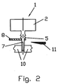
- the Opening 9 and the pin 4 with the neck 7 are in alignment with each other aligned.
- the holding plate 8 lies on a device part, which is not shown in detail and has the gripper 10. In addition, the device still equipped with the cutting knife 11.
- the approach 7 is inserted through the opening 9 until the Bead comes to rest on the edge of the opening 9.
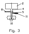
- the approach 7 is then gripped by the gripper 10 and as shown in Figure 3, as long as down pulled until the retaining plate 8 engages in the annular groove 6 of the bead 5. After that the cutting knife 11 advances and separates the attachment 7 from the pin 4.
- FIG. 5 shows the knife 11 then moving away into it Starting position.
- the fastening process between the vibrating mass 2 and the holding plate 8 via the elastic pin 4 is thus ended and the Vibration damper 1 can in a suitable manner in the holding plate 8 Steering wheel to be attached.
Landscapes
- Engineering & Computer Science (AREA)
- General Engineering & Computer Science (AREA)
- Mechanical Engineering (AREA)
- Steering-Linkage Mechanisms And Four-Wheel Steering (AREA)
- Steering Controls (AREA)
- Vibration Prevention Devices (AREA)
- Optical Integrated Circuits (AREA)
- Flanged Joints, Insulating Joints, And Other Joints (AREA)
- Mechanical Coupling Of Light Guides (AREA)
- Fluid-Damping Devices (AREA)
- Vibration Dampers (AREA)
- Perforating, Stamping-Out Or Severing By Means Other Than Cutting (AREA)
Abstract
Description
Claims (1)
- Verfahren zur Befestigung der elastischen Federelemente eines Schwingungstilgers an einer metallenen Halterung, insbesondere eines in einem Lenkrad des Kraftfahrzeugs unterzubringenden Schwingungstilgers an einem Halteblech oder Lenkradboden, wobei die Federelemente die Form von zylindrischen Zapfen haben, die jeweils mit einer eine Ringnut aufweisenden Wulst versehen in entsprechend ausgestaltete Öffnungen im Halteblech einrasten, dadurch gekennzeichnet,dass der Schwingungstilger (1) und das Halteblech (8) übereinander liegend in eine Vorrichtung eingelegt werden, so dass die Zapfen (4) des Schwingungstilgers (1) fluchtend zu den Öffnungen (9) im Halteblech (8) ausgerichtet sind,dass an den Zapfen (4) vorhandene Ansätze (7) durch die Öffnungen (9) hindurchgeführt werden bis das Halteblech (8) an der Wulst (5) anstößt,dass die Ansätze (7) von Greifern (10) erfasst und die Zapfen (4) weiter durch die Öffnungen (9) gezogen werden bis die Ränder der Öffnungen (9) in die Ringnuten (6) einrasten unddass die Ansätze (7) durch Schneidmesser (11) abgetrennt werden.
Applications Claiming Priority (2)
| Application Number | Priority Date | Filing Date | Title |
|---|---|---|---|
| DE10202644A DE10202644C1 (de) | 2002-01-23 | 2002-01-23 | Verfahren zur Befestigung eines Schwingungstilgers an einer Halterung |
| DE10202644 | 2002-01-23 |
Publications (2)
| Publication Number | Publication Date |
|---|---|
| EP1332931A2 true EP1332931A2 (de) | 2003-08-06 |
| EP1332931A3 EP1332931A3 (de) | 2004-10-20 |
Family
ID=7712953
Family Applications (1)
| Application Number | Title | Priority Date | Filing Date |
|---|---|---|---|
| EP02019393A Withdrawn EP1332931A3 (de) | 2002-01-23 | 2002-08-30 | Verfahren zur Befestigung eines Schwingungstilgers an einer Halterung |
Country Status (4)
| Country | Link |
|---|---|
| US (1) | US6807718B2 (de) |
| EP (1) | EP1332931A3 (de) |
| AT (1) | ATE359607T1 (de) |
| DE (2) | DE10202644C1 (de) |
Families Citing this family (21)
| Publication number | Priority date | Publication date | Assignee | Title |
|---|---|---|---|---|
| DE102004045876B4 (de) * | 2004-09-20 | 2006-07-06 | Delphi Technologies, Inc., Troy | Befestigungseinrichtung für ein Lenkstockmodul eines Kraftfahrzeuges |
| DE102006059227A1 (de) * | 2006-12-13 | 2008-06-19 | Hamuel Maschinenbau Gmbh & Co. Kg | Verfahren zur Bearbeitung von Rohlingen und Bearbeitungsmaschine zur Durchführung des Verfahrens |
| US8505701B2 (en) * | 2010-08-18 | 2013-08-13 | Autoliv Asp, Inc. | Mass-damper system |
| US9812684B2 (en) | 2010-11-09 | 2017-11-07 | GM Global Technology Operations LLC | Using elastic averaging for alignment of battery stack, fuel cell stack, or other vehicle assembly |
| JP5272058B2 (ja) | 2011-08-10 | 2013-08-28 | 東洋ゴム工業株式会社 | 防振ユニット |
| US9618026B2 (en) | 2012-08-06 | 2017-04-11 | GM Global Technology Operations LLC | Semi-circular alignment features of an elastic averaging alignment system |
| US9863454B2 (en) | 2013-08-07 | 2018-01-09 | GM Global Technology Operations LLC | Alignment system for providing precise alignment and retention of components of a sealable compartment |
| US9458876B2 (en) | 2013-08-28 | 2016-10-04 | GM Global Technology Operations LLC | Elastically deformable alignment fastener and system |
| US9463831B2 (en) | 2013-09-09 | 2016-10-11 | GM Global Technology Operations LLC | Elastic tube alignment and fastening system for providing precise alignment and fastening of components |
| US9511802B2 (en) | 2013-10-03 | 2016-12-06 | GM Global Technology Operations LLC | Elastically averaged alignment systems and methods |
| US9669774B2 (en) | 2013-10-11 | 2017-06-06 | GM Global Technology Operations LLC | Reconfigurable vehicle interior assembly |
| US9481317B2 (en) | 2013-11-15 | 2016-11-01 | GM Global Technology Operations LLC | Elastically deformable clip and method |
| US9447806B2 (en) | 2013-12-12 | 2016-09-20 | GM Global Technology Operations LLC | Self-retaining alignment system for providing precise alignment and retention of components |
| US9428123B2 (en) | 2013-12-12 | 2016-08-30 | GM Global Technology Operations LLC | Alignment and retention system for a flexible assembly |
| US9446722B2 (en) | 2013-12-19 | 2016-09-20 | GM Global Technology Operations LLC | Elastic averaging alignment member |
| US9599279B2 (en) | 2013-12-19 | 2017-03-21 | GM Global Technology Operations LLC | Elastically deformable module installation assembly |
| US9541113B2 (en) | 2014-01-09 | 2017-01-10 | GM Global Technology Operations LLC | Elastically averaged alignment systems and methods |
| US9428046B2 (en) | 2014-04-02 | 2016-08-30 | GM Global Technology Operations LLC | Alignment and retention system for laterally slideably engageable mating components |
| US9657807B2 (en) | 2014-04-23 | 2017-05-23 | GM Global Technology Operations LLC | System for elastically averaging assembly of components |
| US9429176B2 (en) | 2014-06-30 | 2016-08-30 | GM Global Technology Operations LLC | Elastically averaged alignment systems and methods |
| US9758110B2 (en) | 2015-01-12 | 2017-09-12 | GM Global Technology Operations LLC | Coupling system |
Family Cites Families (7)
| Publication number | Priority date | Publication date | Assignee | Title |
|---|---|---|---|---|
| JPS6231735A (ja) * | 1985-08-05 | 1987-02-10 | Nippon Kokan Kk <Nkk> | 2節振子式動吸振器 |
| US4635892A (en) * | 1985-08-19 | 1987-01-13 | Vibrastop, Inc. | Active vibration suppressor |
| JPH0545588Y2 (de) | 1988-08-08 | 1993-11-22 | ||
| US5906254A (en) * | 1994-10-12 | 1999-05-25 | Lord Corporation | Active systems and devices including active vibration absorbers (AVAS) |
| DE19547714C2 (de) * | 1995-12-20 | 2003-10-23 | Freudenberg Carl Kg | Schwingungstilgeranordnung |
| SE524074C2 (sv) * | 2000-06-02 | 2004-06-22 | Forsheda Ab | Anordning för dämpning av vibrationer hos en vibrationsyta och metoder för montering av en sådan anordning |
| DE10142210C1 (de) * | 2001-08-29 | 2003-05-08 | Freudenberg Carl Kg | Schwingungstilger und dessen Verwendung |
-
2002
- 2002-01-23 DE DE10202644A patent/DE10202644C1/de not_active Expired - Fee Related
- 2002-08-30 EP EP02019393A patent/EP1332931A3/de not_active Withdrawn
-
2003
- 2003-01-13 US US10/342,043 patent/US6807718B2/en not_active Expired - Fee Related
- 2003-01-23 DE DE60313135T patent/DE60313135T2/de not_active Expired - Lifetime
- 2003-01-23 AT AT03701695T patent/ATE359607T1/de not_active IP Right Cessation
Non-Patent Citations (1)
| Title |
|---|
| None * |
Also Published As
| Publication number | Publication date |
|---|---|
| ATE359607T1 (de) | 2007-05-15 |
| DE60313135T2 (de) | 2007-12-13 |
| DE10202644C1 (de) | 2003-06-18 |
| EP1332931A3 (de) | 2004-10-20 |
| DE60313135D1 (de) | 2007-05-24 |
| US6807718B2 (en) | 2004-10-26 |
| US20030145446A1 (en) | 2003-08-07 |
Similar Documents
| Publication | Publication Date | Title |
|---|---|---|
| DE10202644C1 (de) | Verfahren zur Befestigung eines Schwingungstilgers an einer Halterung | |
| EP1216895A2 (de) | Haltevorrichtung | |
| DE19840998B4 (de) | Airbaganordnung bei Fahrzeugen | |
| EP2165875A2 (de) | Befestigungseinrichtung, insbesondere bei Kraftfahrzeugen | |
| DE102020201752B4 (de) | Schwingungsdämpfersystem für eine Lenkradanordnung eines Kraftfahrzeugs | |
| DE60120173T2 (de) | Hubbegrenzung für einen stossdämpfer eines kraftfahrzeuges und herstellverfahren dafür | |
| DE102009055886A1 (de) | Fräsen von Schweißpistolenspitzen | |
| EP2669169B1 (de) | Kettenschaltung für ein Fahrrad | |
| DE19508533C2 (de) | Airbagmodul für Kraftfahrzeuge | |
| DE69719749T2 (de) | Aufhängevorrichtung | |
| DE19908915A1 (de) | Schwingungstilger für ein Lenkrad mit Airbag | |
| DE102018116271A1 (de) | Verfahren zum Verbinden | |
| DE4335072B4 (de) | Airbagvorrichtung für einen Fahrzeugfahrgast | |
| EP0669244A1 (de) | Crashgünstige Aggregatlagerung | |
| DE19948165A1 (de) | Anordnung zur lösbaren Befestigung eines Bauteils an einer Wand | |
| DE69303139T2 (de) | System um ein Aussenkarosserielement an einen Automobilkasten anzubringen | |
| EP3383710B1 (de) | Fahrzeugsicherheitssystem und verfahren zum herstellen eines fahrzeugsicherheitssystems | |
| DE102017208230A1 (de) | Befestigen eines Airbags im Fahrzeug | |
| DE2757844A1 (de) | Tragbares gasmotorgetriebenes schneidwerkzeug | |
| DE102007000329A1 (de) | Umlenkvorrichtung einer Seilsägevorrichtung | |
| DE102008014564A1 (de) | Vorrichtung zum Fördern und Verteilen von Stückgütern mit einem schwingungserregten Förderelement | |
| DE102014007553B4 (de) | Verfahren zum Verbinden von wenigstens zwei Bauteilen sowie Vorrichtung zum Durchführen eines solchen Verfahrens | |
| DE102007002214A1 (de) | Vorrichtung zur Abstützung eines Stoßfängerüberzugs eines Stoßfängers | |
| DE69510349T2 (de) | Werkzeugkupplung mit zentrier- und spanneinrichtungen | |
| DE102005013262A1 (de) | Verfahren zum Anbringen eines Schusskanals an eine Airbagabdeckung mit integrierter Sollbruchlinie und eine verfahrensgemäß hergestellte Baugruppe |
Legal Events
| Date | Code | Title | Description |
|---|---|---|---|
| PUAI | Public reference made under article 153(3) epc to a published international application that has entered the european phase |
Free format text: ORIGINAL CODE: 0009012 |
|
| 17P | Request for examination filed |
Effective date: 20020912 |
|
| AK | Designated contracting states |
Designated state(s): AT BE BG CH CY CZ DE DK EE ES FI FR GB GR IE IT LI LU MC NL PT SE SK TR |
|
| AX | Request for extension of the european patent |
Extension state: AL LT LV MK RO SI |
|
| PUAL | Search report despatched |
Free format text: ORIGINAL CODE: 0009013 |
|
| AK | Designated contracting states |
Kind code of ref document: A3 Designated state(s): AT BE BG CH CY CZ DE DK EE ES FI FR GB GR IE IT LI LU MC NL PT SE SK TR |
|
| AX | Request for extension of the european patent |
Extension state: AL LT LV MK RO SI |
|
| RIC1 | Information provided on ipc code assigned before grant |
Ipc: 7F 16F 7/108 B Ipc: 7B 60R 21/20 A |
|
| AKX | Designation fees paid |
Designated state(s): DE FR SE |
|
| 17Q | First examination report despatched |
Effective date: 20060814 |
|
| GRAP | Despatch of communication of intention to grant a patent |
Free format text: ORIGINAL CODE: EPIDOSNIGR1 |
|
| RIC1 | Information provided on ipc code assigned before grant |
Ipc: F16F 7/104 20060101ALI20070102BHEP Ipc: F16F 7/108 20060101ALI20070102BHEP Ipc: B60R 21/20 20060101AFI20070102BHEP |
|
| STAA | Information on the status of an ep patent application or granted ep patent |
Free format text: STATUS: THE APPLICATION IS DEEMED TO BE WITHDRAWN |
|
| 18D | Application deemed to be withdrawn |
Effective date: 20070616 |