EP1333189A2 - Fahrzeug mit Bremse sowie Einzelradaufhängung - Google Patents
Fahrzeug mit Bremse sowie Einzelradaufhängung Download PDFInfo
- Publication number
- EP1333189A2 EP1333189A2 EP03075351A EP03075351A EP1333189A2 EP 1333189 A2 EP1333189 A2 EP 1333189A2 EP 03075351 A EP03075351 A EP 03075351A EP 03075351 A EP03075351 A EP 03075351A EP 1333189 A2 EP1333189 A2 EP 1333189A2
- Authority
- EP
- European Patent Office
- Prior art keywords
- wheel
- actuator
- pivot pin
- arm member
- vehicle according
- Prior art date
- Legal status (The legal status is an assumption and is not a legal conclusion. Google has not performed a legal analysis and makes no representation as to the accuracy of the status listed.)
- Granted
Links
- 239000000725 suspension Substances 0.000 title claims abstract description 19
- 238000010276 construction Methods 0.000 title claims abstract description 17
- 230000005540 biological transmission Effects 0.000 claims abstract description 28
- 230000033001 locomotion Effects 0.000 claims abstract description 19
- 230000035939 shock Effects 0.000 description 5
- 239000006096 absorbing agent Substances 0.000 description 2
- 230000003213 activating effect Effects 0.000 description 1
- 230000006978 adaptation Effects 0.000 description 1
- 230000002411 adverse Effects 0.000 description 1
- 239000007787 solid Substances 0.000 description 1
Images



Classifications
-
- B—PERFORMING OPERATIONS; TRANSPORTING
- B60—VEHICLES IN GENERAL
- B60G—VEHICLE SUSPENSION ARRANGEMENTS
- B60G3/00—Resilient suspensions for a single wheel
- B60G3/02—Resilient suspensions for a single wheel with a single pivoted arm
- B60G3/12—Resilient suspensions for a single wheel with a single pivoted arm the arm being essentially parallel to the longitudinal axis of the vehicle
- B60G3/14—Resilient suspensions for a single wheel with a single pivoted arm the arm being essentially parallel to the longitudinal axis of the vehicle the arm being rigid
- B60G3/145—Resilient suspensions for a single wheel with a single pivoted arm the arm being essentially parallel to the longitudinal axis of the vehicle the arm being rigid the arm forming the axle housing
-
- F—MECHANICAL ENGINEERING; LIGHTING; HEATING; WEAPONS; BLASTING
- F16—ENGINEERING ELEMENTS AND UNITS; GENERAL MEASURES FOR PRODUCING AND MAINTAINING EFFECTIVE FUNCTIONING OF MACHINES OR INSTALLATIONS; THERMAL INSULATION IN GENERAL
- F16D—COUPLINGS FOR TRANSMITTING ROTATION; CLUTCHES; BRAKES
- F16D65/00—Parts or details
- F16D65/14—Actuating mechanisms for brakes; Means for initiating operation at a predetermined position
- F16D65/16—Actuating mechanisms for brakes; Means for initiating operation at a predetermined position arranged in or on the brake
- F16D65/22—Actuating mechanisms for brakes; Means for initiating operation at a predetermined position arranged in or on the brake adapted for pressing members apart, e.g. for drum brakes
-
- F—MECHANICAL ENGINEERING; LIGHTING; HEATING; WEAPONS; BLASTING
- F16—ENGINEERING ELEMENTS AND UNITS; GENERAL MEASURES FOR PRODUCING AND MAINTAINING EFFECTIVE FUNCTIONING OF MACHINES OR INSTALLATIONS; THERMAL INSULATION IN GENERAL
- F16D—COUPLINGS FOR TRANSMITTING ROTATION; CLUTCHES; BRAKES
- F16D65/00—Parts or details
- F16D65/14—Actuating mechanisms for brakes; Means for initiating operation at a predetermined position
- F16D65/28—Actuating mechanisms for brakes; Means for initiating operation at a predetermined position arranged apart from the brake
-
- F—MECHANICAL ENGINEERING; LIGHTING; HEATING; WEAPONS; BLASTING
- F16—ENGINEERING ELEMENTS AND UNITS; GENERAL MEASURES FOR PRODUCING AND MAINTAINING EFFECTIVE FUNCTIONING OF MACHINES OR INSTALLATIONS; THERMAL INSULATION IN GENERAL
- F16D—COUPLINGS FOR TRANSMITTING ROTATION; CLUTCHES; BRAKES
- F16D2125/00—Components of actuators
- F16D2125/18—Mechanical mechanisms
- F16D2125/20—Mechanical mechanisms converting rotation to linear movement or vice versa
- F16D2125/22—Mechanical mechanisms converting rotation to linear movement or vice versa acting transversely to the axis of rotation
- F16D2125/28—Cams; Levers with cams
-
- F—MECHANICAL ENGINEERING; LIGHTING; HEATING; WEAPONS; BLASTING
- F16—ENGINEERING ELEMENTS AND UNITS; GENERAL MEASURES FOR PRODUCING AND MAINTAINING EFFECTIVE FUNCTIONING OF MACHINES OR INSTALLATIONS; THERMAL INSULATION IN GENERAL
- F16D—COUPLINGS FOR TRANSMITTING ROTATION; CLUTCHES; BRAKES
- F16D2125/00—Components of actuators
- F16D2125/18—Mechanical mechanisms
- F16D2125/58—Mechanical mechanisms transmitting linear movement
- F16D2125/64—Levers
Definitions
- the invention relates to a vehicle on wheels, which vehicle comprises brake means for braking at least one of the wheels, which at least one wheel is rotatable about a wheel axle, which brake means comprise a friction element which can be pressed against the wheel or against a part rotating along with said wheel, an actuator positioned on the outer side of said at least one wheel, which comprises an actuator element capable of reciprocating motion for moving a transmission element fitted with a pivot pin extending between the ends thereof, which transmission element is connected to the actuator element on the one hand and to the friction element on the other hand for actuating the friction element.
- a vehicle such as a truck or a trailer, in order to be able to brake, is fitted with a brake arrangement comprising a pneumatically operating cylinder which, upon being energized, causes a cylinder rod to move in its longitudinal direction. Said movement is transmitted to a pivotable brake arm via a transmission rod, which brake arm is in turn connected to a friction element, as in a drum brake or disc brake system, which friction element is pressed against the wheel or against a part rotating along with said wheel upon suitable pivoting of the brake arm.
- the friction force thus generated causes the wheel to be braked and the vehicle to come to a standstill, if desired.
- the cylinder rod and the transmission rod are in line or joihtly form an integral (cylinder) rod, so that the movement of the cylinder rod is rectilinearly transmitted to the brake arm that is connected to the friction element.
- the cylinder rod and the separate transmission rod that may be provided are subjected to pressure.
- This manner of transmission is disadvantageous in certain respects as regards the physical characteristics of the brake arrangement as a whole, which has to comply with the strictest requirements.
- the cylinder rod and the transmission rod must not vibrate under the influence of the force from the actuator, and the frictional resistance thereof must be kept as low as possible so as to enhance the efficiency of the brake arrangement. This means that lateral forces on the transmission element must be avoided.
- the rectilinear transmission as described above is realised by having the direction of operation of the actuator extend towards the point of engagement of the transmission rod on the brake arm.
- the brake cylinder is usually disposed beside the wheel, seen in top plan view, diagonally above the central axis of the wheel, usually near the wheel suspension.
- a vehicle as referred to in the introduction is known from US patent No 2,516,160, in which the piston rod of a pneumatic cylinder for actuation of a drum brake system is oriented parallel to a wheel axle.
- the movement of the piston rod is transmitted to the brake system by means of a relatively complex kinematic system. Due to the complexity of the disclosed configuration, the cost price thereof is high, whilst in addition the piston rod takes up space beside the wheels, seen in axial direction. In particular in the case of trailers said space might also be suitably utilized as cargo space.
- the object of the invention described herein is to provide a brake arrangement for a vehicle, which is constructed in such a manner that the available space within the wheel housing can be optimally utilised.
- the invention provides a vehicle as referred to in the introduction, which is characterized in that the transmission element comprises a lever mechanism comprising a first arm member and a second arm member, which extend from the pivot pin towards, respectively, the actuator element and the friction element, with the first arm member extending at least partially within the width of said at least one wheel and the second arm member extending at least partially outside the width of said at least one wheel.
- the transmission element comprises a lever mechanism comprising a first arm member and a second arm member, which extend from the pivot pin towards, respectively, the actuator element and the friction element, with the first arm member extending at least partially within the width of said at least one wheel and the second arm member extending at least partially outside the width of said at least one wheel.
- the brake means comprise a brake arm which pivots about a brake pivot, which brake arm is connected to the transmission element at a point spaced from said brake pivot.
- the pivot pin it is preferable for the pivot pin to extend outside the diameter of said at least one wheel and/or parallel to the wheel axle. Especially in the case of such a preferred embodiment it is possible to optimally utilise the unused (so far) space in the wheel housings for the brake system, more specifically for the actuator thereof. In addition, especially the fact that the pivot pin extends parallel to the wheel of shaft makes it possible to minimise or eliminate any transverse forces that may occur upon actuation of the brake means.
- the actuator element extends within the width of said at least one wheel during movement thereof, which movement is even more preferably oriented perpendicularly to the wheel axle.
- the amount of space that is taken up in a disadvantageous manner by the actuator is minimised or eliminated altogether if the actuator extends within the width of said at least one wheel.
- the pivot pin is preferably supported in bearings on two sides.
- the two arm members preferably engage the pivot pin at positions between the two bearings in that case.
- Said bracket can furthermore be employed in a useful manner by connecting the actuator to the bracket.
- the invention furthermore relates to an independent wheel suspension construction for use in a vehicle according to any one of the preceding claims, comprising a frame for mounting the independent wheel suspension construction on the chassis of the vehicle, a supporting arm connected to the frame, which supports a wheel which rotates about a wheel axle, brake means for braking said wheel, which brake means are provided with a friction element which can be pressed against the wheel or against a part rotating along with said wheel, an actuator connected to said supporting arm, which is positioned on the outer side of said at least one wheel, which actuator comprises an actuator element capable of reciprocating motion for moving a transmission element fitted with a pivot pin extending between its ends, which transmission element is connected to the actuator element on the one hand and to the friction element on the other hand for actuating the friction element, in which the transmission element comprises a lever mechanism comprising a first arm member and a second arm member, which extend from said pivot pin towards, respectively, the actuator element and the friction element, with the first arm member extending at least partially within the width of said at least one wheel and the second arm
- the supporting arm is preferably pin-pivoted to the frame.
- the pivot pin is rotatably journalled with respect to the supporting arm, or at least with respect to a part connected thereto.
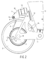
- FIGS 1-4 are various views of the assembly 1 of a wheel 2 with the wheel suspension and the brake arrangement according to the invention.
- the assembly 1, which is an independent wheel suspension construction, is intended for being mounted on the chassis of a trailer.
- the wheel 2 and the associated wheel axle 18 are mounted on a supporting arm 11, which is pivotally connected to a chassis part 12 about a suspension axle 25.
- the independent wheel suspension construction 1 is mounted on the trailer chassis (not shown) via the chassis part 12.
- the supporting arm 11 is furthermore supported on the chassis part 12 via a shock absorber 13 and a shock absorber 14.
- the brake arrangement being used consists of a brake drum 3, which can be actuated by means of a brake arm 4, which pivots about a pin 17 which is fixedly disposed with respect to the wheel 2.
- the brake arm 4 is connected to the cylinder rod 9 of the pneumatic cylinder 10 by means of a rod 5 and a lever mechanism 6 comprising arm members 7 and 8.
- the lever mechanism 6 can pivot as a result of pivoting movement of the pivot pin 15, which forms part of the lever mechanism 6 and which is bearing-mounted in the two legs of the U-shaped mounting bracket 16.
- the pivot pin 15 extends parallel to the wheel axle 18 outside the diameter of the wheel 2.
- the mounting bracket 16 is connected to the supporting arm 11 by means of a solid mounting strip 19, so that any shocks of the wheel 2 caused by road bumps will not affect the operation of the brake arrangement.
- the arm member 7 extends within the width of the wheel 2 whilst being connected to the pivot pin 15 at a position located within said width as well, whereas the arm member 8 extends outside the width of the wheel 2 whilst being connected to the pivot pin 15 at a position located outside said width as well.
- the arm members 7 and 8 extend substantially parallel to each other, viz. perpendicularly to the wheel axle 18.
- the cylinder rod 9 When the pneumatic cylinder 10 is suitably actuated, in a manner which is known per se, the cylinder rod 9 is pushed in forward direction by the cylinder 10, which movement is converted into a pulling movement on the rod 5, via the arm member 7 and the arm member 8 of the lever mechanism 6. During said movement, which takes place in a direction perpendicularly to the wheel axle 18, the arm member 7 remains within the width of the wheel 2.
- the movement of the cylinder rod 9 causes the brake arm 4 to pivot in clockwise direction about the pivot pin 17, as a result of which the brake drum 3 is energized in a manner which is known per se.
- the length of the arm members 7 and 8 introduces yet another degree of freedom. This makes it possible inter alia to adapt the spacing between the cylinder 10 and the wheel 2. If the angle which the arm members 7 and 8 include with each other in the plane perpendicularly to the pivot pin 15 is furthermore varied, the position and the direction of operation of the actuator 10 can be fully adapted to the requirements of the person skilled in the art. Moreover, all these adaptations can be effected without the physical characteristics of the brake arrangement being adversely affected.
Landscapes
- Engineering & Computer Science (AREA)
- General Engineering & Computer Science (AREA)
- Mechanical Engineering (AREA)
- Braking Arrangements (AREA)
Applications Claiming Priority (2)
| Application Number | Priority Date | Filing Date | Title |
|---|---|---|---|
| NL1019900A NL1019900C2 (nl) | 2002-02-05 | 2002-02-05 | Voertuig omvattende remmiddelen alsmede onafhankelijke wielophangingsconstructie. |
| NL1019900 | 2002-02-05 |
Publications (3)
| Publication Number | Publication Date |
|---|---|
| EP1333189A2 true EP1333189A2 (de) | 2003-08-06 |
| EP1333189A3 EP1333189A3 (de) | 2003-09-03 |
| EP1333189B1 EP1333189B1 (de) | 2005-08-31 |
Family
ID=19774486
Family Applications (1)
| Application Number | Title | Priority Date | Filing Date |
|---|---|---|---|
| EP03075351A Expired - Lifetime EP1333189B1 (de) | 2002-02-05 | 2003-02-05 | Fahrzeug mit Bremse sowie Einzelradaufhängung |
Country Status (4)
| Country | Link |
|---|---|
| EP (1) | EP1333189B1 (de) |
| AT (1) | ATE303527T1 (de) |
| DE (1) | DE60301411T2 (de) |
| NL (1) | NL1019900C2 (de) |
Cited By (4)
| Publication number | Priority date | Publication date | Assignee | Title |
|---|---|---|---|---|
| EP1772296A1 (de) | 2005-10-10 | 2007-04-11 | Transport Industry Development Centre B.V. | Fahrzeug |
| CN108622045A (zh) * | 2017-03-24 | 2018-10-09 | 约斯特(中国)汽车部件有限公司 | 车辆制动装置及包括其的车辆 |
| CN108621733A (zh) * | 2017-03-24 | 2018-10-09 | 约斯特(中国)汽车部件有限公司 | 车辆悬挂装置及包括其的车辆 |
| CN108622044A (zh) * | 2017-03-24 | 2018-10-09 | 约斯特(中国)汽车部件有限公司 | 车辆制动装置及包括其的车辆 |
Citations (1)
| Publication number | Priority date | Publication date | Assignee | Title |
|---|---|---|---|---|
| US2516160A (en) | 1946-07-11 | 1950-07-25 | Timken Axle Co Detroit | Brake |
Family Cites Families (3)
| Publication number | Priority date | Publication date | Assignee | Title |
|---|---|---|---|---|
| GB359243A (en) * | 1930-11-11 | 1931-10-22 | Elektronmetall Ges Mit Beschra | Landing wheel, with brake for flying machines |
| GB575645A (en) * | 1944-03-02 | 1946-02-27 | Westinghouse Brake & Signal | Improvements relating to fluid pressure brake cylinders for road and other vehicles |
| US6260645B1 (en) * | 1999-04-22 | 2001-07-17 | Daimlerchrysler Corporation | Electric vehicle with a movable battery tray mounted between frame rails |
-
2002
- 2002-02-05 NL NL1019900A patent/NL1019900C2/nl not_active IP Right Cessation
-
2003
- 2003-02-05 DE DE60301411T patent/DE60301411T2/de not_active Expired - Lifetime
- 2003-02-05 AT AT03075351T patent/ATE303527T1/de not_active IP Right Cessation
- 2003-02-05 EP EP03075351A patent/EP1333189B1/de not_active Expired - Lifetime
Patent Citations (1)
| Publication number | Priority date | Publication date | Assignee | Title |
|---|---|---|---|---|
| US2516160A (en) | 1946-07-11 | 1950-07-25 | Timken Axle Co Detroit | Brake |
Cited By (6)
| Publication number | Priority date | Publication date | Assignee | Title |
|---|---|---|---|---|
| EP1772296A1 (de) | 2005-10-10 | 2007-04-11 | Transport Industry Development Centre B.V. | Fahrzeug |
| NL1030146C2 (nl) * | 2005-10-10 | 2007-04-11 | Transp Industry Dev Ct Bv | Voertuig. |
| CN108622045A (zh) * | 2017-03-24 | 2018-10-09 | 约斯特(中国)汽车部件有限公司 | 车辆制动装置及包括其的车辆 |
| CN108621733A (zh) * | 2017-03-24 | 2018-10-09 | 约斯特(中国)汽车部件有限公司 | 车辆悬挂装置及包括其的车辆 |
| CN108622044A (zh) * | 2017-03-24 | 2018-10-09 | 约斯特(中国)汽车部件有限公司 | 车辆制动装置及包括其的车辆 |
| CN108621733B (zh) * | 2017-03-24 | 2024-05-28 | 约斯特(中国)汽车部件有限公司 | 车辆悬挂装置及包括其的车辆 |
Also Published As
| Publication number | Publication date |
|---|---|
| NL1019900C2 (nl) | 2003-08-07 |
| EP1333189A3 (de) | 2003-09-03 |
| DE60301411D1 (de) | 2005-10-06 |
| DE60301411T2 (de) | 2006-06-08 |
| ATE303527T1 (de) | 2005-09-15 |
| EP1333189B1 (de) | 2005-08-31 |
Similar Documents
| Publication | Publication Date | Title |
|---|---|---|
| CA2496758A1 (en) | Manually actuated brake system for manually towable vehicle | |
| CA2764798C (en) | Bolster mounted brake system | |
| CN107097893A (zh) | 用于车轮的轮缘制动系统 | |
| CA3065998C (en) | Suspension caster with brake lever and wheel fork and yoke portion having common pivot axis | |
| EP1333189B1 (de) | Fahrzeug mit Bremse sowie Einzelradaufhängung | |
| CA2298286C (en) | An adapter system for a railway vehicle braking system | |
| US5785159A (en) | Braking mechanism for railroad cars having both pneumatic and mechanical actuators | |
| CA2442787C (en) | Improved hand brake lever interface for single-cylinder truck-mounted railway car brake | |
| PL187645B1 (pl) | Urządzenie do podnoszenia osi pojazdu z zawieszeniem pneumatycznym | |
| US5167304A (en) | Drum brake torsion/compression strut spring | |
| JPH09506691A (ja) | カム操作式パーキングブレーキレバー付きドラムブレーキ | |
| US5538112A (en) | Parking and emergancy brake actuating lever for drum brake assembly | |
| CN101103209A (zh) | 机械盘式制动组件 | |
| JP6660216B2 (ja) | ブレーキ支持部材及びこれを備えるブレーキ装置 | |
| US6116382A (en) | Braking device for a railway vehicle | |
| US20110005347A1 (en) | parking brake arrangement | |
| EP0085252B1 (de) | Scheibenbrems- und Fahrzeugachsanordnung und Sattelanordnung für eine Scheibenbremse | |
| JP3711330B2 (ja) | ディスクブレーキ装置 | |
| EP0879751A1 (de) | Verbessertes Drehgestell für Schienenfahrzeuge | |
| JP2001260831A (ja) | トレーラの制動装置 | |
| JP2022024864A (ja) | 手押し運搬車の制動装置 | |
| GB1559421A (en) | Apparatus for detecting exessive play in vehicle components | |
| JPS6121329Y2 (de) | ||
| EP1447584A2 (de) | Hydraulisch und mechanisch betätigbare Scheibenbremse | |
| GB2078881A (en) | Railway vehicle braking system |
Legal Events
| Date | Code | Title | Description |
|---|---|---|---|
| PUAI | Public reference made under article 153(3) epc to a published international application that has entered the european phase |
Free format text: ORIGINAL CODE: 0009012 |
|
| PUAL | Search report despatched |
Free format text: ORIGINAL CODE: 0009013 |
|
| AK | Designated contracting states |
Designated state(s): AT BE BG CH CY CZ DE DK EE ES FI FR GB GR HU IE IT LI LU MC NL PT SE SI SK TR |
|
| AX | Request for extension of the european patent |
Extension state: AL LT LV MK RO |
|
| AK | Designated contracting states |
Kind code of ref document: A3 Designated state(s): AT BE BG CH CY CZ DE DK EE ES FI FR GB GR HU IE IT LI LU MC NL PT SE SI SK TR |
|
| AX | Request for extension of the european patent |
Extension state: AL LT LV MK RO |
|
| RIC1 | Information provided on ipc code assigned before grant |
Ipc: 7B 60G 3/12 B Ipc: 7B 60T 1/06 B Ipc: 7F 16D 65/28 A |
|
| 17P | Request for examination filed |
Effective date: 20040302 |
|
| AKX | Designation fees paid |
Designated state(s): AT BE BG CH CY CZ DE DK EE ES FI FR GB GR HU IE IT LI LU MC NL PT SE SI SK TR |
|
| 17Q | First examination report despatched |
Effective date: 20040616 |
|
| GRAP | Despatch of communication of intention to grant a patent |
Free format text: ORIGINAL CODE: EPIDOSNIGR1 |
|
| GRAS | Grant fee paid |
Free format text: ORIGINAL CODE: EPIDOSNIGR3 |
|
| GRAA | (expected) grant |
Free format text: ORIGINAL CODE: 0009210 |
|
| AK | Designated contracting states |
Kind code of ref document: B1 Designated state(s): AT BE BG CH CY CZ DE DK EE ES FI FR GB GR HU IE IT LI LU MC NL PT SE SI SK TR |
|
| PG25 | Lapsed in a contracting state [announced via postgrant information from national office to epo] |
Ref country code: IT Free format text: LAPSE BECAUSE OF FAILURE TO SUBMIT A TRANSLATION OF THE DESCRIPTION OR TO PAY THE FEE WITHIN THE PRESCRIBED TIME-LIMIT;WARNING: LAPSES OF ITALIAN PATENTS WITH EFFECTIVE DATE BEFORE 2007 MAY HAVE OCCURRED AT ANY TIME BEFORE 2007. THE CORRECT EFFECTIVE DATE MAY BE DIFFERENT FROM THE ONE RECORDED. Effective date: 20050831 Ref country code: AT Free format text: LAPSE BECAUSE OF FAILURE TO SUBMIT A TRANSLATION OF THE DESCRIPTION OR TO PAY THE FEE WITHIN THE PRESCRIBED TIME-LIMIT Effective date: 20050831 Ref country code: CZ Free format text: LAPSE BECAUSE OF FAILURE TO SUBMIT A TRANSLATION OF THE DESCRIPTION OR TO PAY THE FEE WITHIN THE PRESCRIBED TIME-LIMIT Effective date: 20050831 Ref country code: SI Free format text: LAPSE BECAUSE OF FAILURE TO SUBMIT A TRANSLATION OF THE DESCRIPTION OR TO PAY THE FEE WITHIN THE PRESCRIBED TIME-LIMIT Effective date: 20050831 Ref country code: CH Free format text: LAPSE BECAUSE OF FAILURE TO SUBMIT A TRANSLATION OF THE DESCRIPTION OR TO PAY THE FEE WITHIN THE PRESCRIBED TIME-LIMIT Effective date: 20050831 Ref country code: FI Free format text: LAPSE BECAUSE OF FAILURE TO SUBMIT A TRANSLATION OF THE DESCRIPTION OR TO PAY THE FEE WITHIN THE PRESCRIBED TIME-LIMIT Effective date: 20050831 Ref country code: LI Free format text: LAPSE BECAUSE OF FAILURE TO SUBMIT A TRANSLATION OF THE DESCRIPTION OR TO PAY THE FEE WITHIN THE PRESCRIBED TIME-LIMIT Effective date: 20050831 Ref country code: BE Free format text: LAPSE BECAUSE OF FAILURE TO SUBMIT A TRANSLATION OF THE DESCRIPTION OR TO PAY THE FEE WITHIN THE PRESCRIBED TIME-LIMIT Effective date: 20050831 Ref country code: SK Free format text: LAPSE BECAUSE OF FAILURE TO SUBMIT A TRANSLATION OF THE DESCRIPTION OR TO PAY THE FEE WITHIN THE PRESCRIBED TIME-LIMIT Effective date: 20050831 |
|
| REG | Reference to a national code |
Ref country code: CH Ref legal event code: EP Ref country code: GB Ref legal event code: FG4D |
|
| REG | Reference to a national code |
Ref country code: IE Ref legal event code: FG4D |
|
| REF | Corresponds to: |
Ref document number: 60301411 Country of ref document: DE Date of ref document: 20051006 Kind code of ref document: P |
|
| PG25 | Lapsed in a contracting state [announced via postgrant information from national office to epo] |
Ref country code: DK Free format text: LAPSE BECAUSE OF FAILURE TO SUBMIT A TRANSLATION OF THE DESCRIPTION OR TO PAY THE FEE WITHIN THE PRESCRIBED TIME-LIMIT Effective date: 20051130 Ref country code: GR Free format text: LAPSE BECAUSE OF FAILURE TO SUBMIT A TRANSLATION OF THE DESCRIPTION OR TO PAY THE FEE WITHIN THE PRESCRIBED TIME-LIMIT Effective date: 20051130 Ref country code: BG Free format text: LAPSE BECAUSE OF FAILURE TO SUBMIT A TRANSLATION OF THE DESCRIPTION OR TO PAY THE FEE WITHIN THE PRESCRIBED TIME-LIMIT Effective date: 20051130 Ref country code: SE Free format text: LAPSE BECAUSE OF FAILURE TO SUBMIT A TRANSLATION OF THE DESCRIPTION OR TO PAY THE FEE WITHIN THE PRESCRIBED TIME-LIMIT Effective date: 20051130 |
|
| PG25 | Lapsed in a contracting state [announced via postgrant information from national office to epo] |
Ref country code: ES Free format text: LAPSE BECAUSE OF FAILURE TO SUBMIT A TRANSLATION OF THE DESCRIPTION OR TO PAY THE FEE WITHIN THE PRESCRIBED TIME-LIMIT Effective date: 20051212 |
|
| PG25 | Lapsed in a contracting state [announced via postgrant information from national office to epo] |
Ref country code: IE Free format text: LAPSE BECAUSE OF NON-PAYMENT OF DUE FEES Effective date: 20060206 |
|
| PG25 | Lapsed in a contracting state [announced via postgrant information from national office to epo] |
Ref country code: PT Free format text: LAPSE BECAUSE OF FAILURE TO SUBMIT A TRANSLATION OF THE DESCRIPTION OR TO PAY THE FEE WITHIN THE PRESCRIBED TIME-LIMIT Effective date: 20060223 |
|
| PG25 | Lapsed in a contracting state [announced via postgrant information from national office to epo] |
Ref country code: MC Free format text: LAPSE BECAUSE OF NON-PAYMENT OF DUE FEES Effective date: 20060228 Ref country code: LU Free format text: LAPSE BECAUSE OF NON-PAYMENT OF DUE FEES Effective date: 20060228 |
|
| PG25 | Lapsed in a contracting state [announced via postgrant information from national office to epo] |
Ref country code: HU Free format text: LAPSE BECAUSE OF FAILURE TO SUBMIT A TRANSLATION OF THE DESCRIPTION OR TO PAY THE FEE WITHIN THE PRESCRIBED TIME-LIMIT Effective date: 20060301 |
|
| REG | Reference to a national code |
Ref country code: CH Ref legal event code: PL |
|
| PLBE | No opposition filed within time limit |
Free format text: ORIGINAL CODE: 0009261 |
|
| STAA | Information on the status of an ep patent application or granted ep patent |
Free format text: STATUS: NO OPPOSITION FILED WITHIN TIME LIMIT |
|
| 26N | No opposition filed |
Effective date: 20060601 |
|
| EN | Fr: translation not filed | ||
| PG25 | Lapsed in a contracting state [announced via postgrant information from national office to epo] |
Ref country code: FR Free format text: LAPSE BECAUSE OF FAILURE TO SUBMIT A TRANSLATION OF THE DESCRIPTION OR TO PAY THE FEE WITHIN THE PRESCRIBED TIME-LIMIT Effective date: 20061027 |
|
| REG | Reference to a national code |
Ref country code: IE Ref legal event code: MM4A |
|
| PG25 | Lapsed in a contracting state [announced via postgrant information from national office to epo] |
Ref country code: EE Free format text: LAPSE BECAUSE OF FAILURE TO SUBMIT A TRANSLATION OF THE DESCRIPTION OR TO PAY THE FEE WITHIN THE PRESCRIBED TIME-LIMIT Effective date: 20050831 |
|
| PG25 | Lapsed in a contracting state [announced via postgrant information from national office to epo] |
Ref country code: TR Free format text: LAPSE BECAUSE OF FAILURE TO SUBMIT A TRANSLATION OF THE DESCRIPTION OR TO PAY THE FEE WITHIN THE PRESCRIBED TIME-LIMIT Effective date: 20050831 |
|
| PG25 | Lapsed in a contracting state [announced via postgrant information from national office to epo] |
Ref country code: FR Free format text: LAPSE BECAUSE OF FAILURE TO SUBMIT A TRANSLATION OF THE DESCRIPTION OR TO PAY THE FEE WITHIN THE PRESCRIBED TIME-LIMIT Effective date: 20050831 Ref country code: CY Free format text: LAPSE BECAUSE OF FAILURE TO SUBMIT A TRANSLATION OF THE DESCRIPTION OR TO PAY THE FEE WITHIN THE PRESCRIBED TIME-LIMIT Effective date: 20050831 |
|
| PGFP | Annual fee paid to national office [announced via postgrant information from national office to epo] |
Ref country code: GB Payment date: 20220223 Year of fee payment: 20 Ref country code: DE Payment date: 20220217 Year of fee payment: 20 |
|
| PGFP | Annual fee paid to national office [announced via postgrant information from national office to epo] |
Ref country code: NL Payment date: 20220216 Year of fee payment: 20 |
|
| REG | Reference to a national code |
Ref country code: DE Ref legal event code: R071 Ref document number: 60301411 Country of ref document: DE |
|
| REG | Reference to a national code |
Ref country code: NL Ref legal event code: MK Effective date: 20230204 |
|
| REG | Reference to a national code |
Ref country code: GB Ref legal event code: PE20 Expiry date: 20230204 |
|
| PG25 | Lapsed in a contracting state [announced via postgrant information from national office to epo] |
Ref country code: GB Free format text: LAPSE BECAUSE OF EXPIRATION OF PROTECTION Effective date: 20230204 |