EP1447584A2 - Hydraulisch und mechanisch betätigbare Scheibenbremse - Google Patents
Hydraulisch und mechanisch betätigbare Scheibenbremse Download PDFInfo
- Publication number
- EP1447584A2 EP1447584A2 EP04425049A EP04425049A EP1447584A2 EP 1447584 A2 EP1447584 A2 EP 1447584A2 EP 04425049 A EP04425049 A EP 04425049A EP 04425049 A EP04425049 A EP 04425049A EP 1447584 A2 EP1447584 A2 EP 1447584A2
- Authority
- EP
- European Patent Office
- Prior art keywords
- brake
- piston
- disc
- disc brake
- mechanical
- Prior art date
- Legal status (The legal status is an assumption and is not a legal conclusion. Google has not performed a legal analysis and makes no representation as to the accuracy of the status listed.)
- Withdrawn
Links
- 230000009977 dual effect Effects 0.000 claims description 2
- 230000001747 exhibiting effect Effects 0.000 claims description 2
- 238000013022 venting Methods 0.000 claims description 2
- 230000006978 adaptation Effects 0.000 claims 1
- 238000007789 sealing Methods 0.000 claims 1
- 239000002783 friction material Substances 0.000 description 4
- 239000012530 fluid Substances 0.000 description 3
- XAGFODPZIPBFFR-UHFFFAOYSA-N aluminium Chemical compound [Al] XAGFODPZIPBFFR-UHFFFAOYSA-N 0.000 description 1
- 229910052782 aluminium Inorganic materials 0.000 description 1
- 239000004411 aluminium Substances 0.000 description 1
Images


Classifications
-
- F—MECHANICAL ENGINEERING; LIGHTING; HEATING; WEAPONS; BLASTING
- F16—ENGINEERING ELEMENTS AND UNITS; GENERAL MEASURES FOR PRODUCING AND MAINTAINING EFFECTIVE FUNCTIONING OF MACHINES OR INSTALLATIONS; THERMAL INSULATION IN GENERAL
- F16D—COUPLINGS FOR TRANSMITTING ROTATION; CLUTCHES; BRAKES
- F16D55/00—Brakes with substantially-radial braking surfaces pressed together in axial direction, e.g. disc brakes
- F16D55/02—Brakes with substantially-radial braking surfaces pressed together in axial direction, e.g. disc brakes with axially-movable discs or pads pressed against axially-located rotating members
- F16D55/22—Brakes with substantially-radial braking surfaces pressed together in axial direction, e.g. disc brakes with axially-movable discs or pads pressed against axially-located rotating members by clamping an axially-located rotating disc between movable braking members, e.g. movable brake discs or brake pads
- F16D55/224—Brakes with substantially-radial braking surfaces pressed together in axial direction, e.g. disc brakes with axially-movable discs or pads pressed against axially-located rotating members by clamping an axially-located rotating disc between movable braking members, e.g. movable brake discs or brake pads with a common actuating member for the braking members
Definitions
- the present finding in general relates to disc brakes for motor vehicles, and in particular it refers to a hydro-mechanical brake for light four-wheelers.
- main braking system also called working or service system
- auxiliary braking system also called parking or emergency system
- disc brakes capable of combining in a single control unit a fluid mechanical control, typical of the main braking system, and a mechanical control, typical of the auxiliary braking system.
- a former application for Utility Model No. MI98U000782 describes a disc brake wherein the fluid mechanical control and the mechanical control are respectively realised with at least one fluid mechanical piston and at least one mechanical pusher placed one inside the other and having, at least in one braking position, respective surfaces forcing the friction material and adjacent to each other.
- the actuators relative to the two braking systems are separate, even though they are combined into a single structure.
- Object of the present invention is that of proposing a hydro-mechanical disc brake, that is, capable of combining a hydraulic control and a mechanical control into a single unit, having a new and original structure, more compact and lighter than the similar brakes of the prior art, and realised with a smaller number of components.
- Another object of the invention is that of providing a disc brake of the hydro-mechanical type provided with a single actuator controllable both hydraulically, for a device operation as main brake, and mechanically, for an operation as auxiliary brake.
- Yet another object of the finding is that of providing a hydro-mechanical disc brake having a single-bloc body that allows an arrangement of the components required for the mechanical operation of the device according to two orientations orthogonal to one another according to the vehicle to which the brake will be fitted.
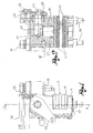
- Fig. 1 shows a side view of the brake under discussion
- Fig. 2 shows a section view of the brake according to line II-II in Fig. 1;
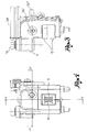
- Fig. 3 shows a view of the brake seen from the side opposed to that of Fig. 1;
- Fig. 4 shows a front view of the brake
- Fig. 5 shows a section view of the brake according to line V-V in Fig. 4;
- Fig. 6 shows a section view of the brake according to line VI-VI in Fig. 4;
- Fig. 7 shows a perspective view of the brake of the previous Figures.
- Fig. 8 shows a perspective view of the brake with a different arrangement of its mechanical actuating means.
- the disc brake under discussion comprises a single-bloc caliper body 11, totally made of aluminium, wherein there is obtained an aperture 12 delimited by parallel walls 12'. On each of said walls there is mounted a plate 13 carrying a friction material or pad 13', the two pads being sided at opposed sides to a brake disc 14 integral with the wheel to be braked (Figs. 7, 8).
- the caliper body 11 supports plates 13 by a single pin 15 around which there is mounted a helical return spring 16 exhibiting a dual conical profile.
- body 11 is constrained to a plate 17 integral to the vehicle chassis by fixed sliding bushes 18 locked to said plate by fastening screws 19.
- the caliper body 11 is shows floating on bushes 18 so as to partly slide on them, transversally relative to the brake disc 14. Suitable guards 18' are arranged between the sliding bushes 18 and body 11.
- a single piston 20 is arranged into the caliper body 11, actuable both hydraulically and mechanically to push the friction material 13' against the brake disc 14.
- Piston 20 is oriented perpendicularly to plates 13 and acts by engaging one of them with one of its end surfaces 20'.
- piston 20 ends with a control head 21 interacting with a cam portion 22 of a pin 22' arranged into the caliper body 11, orthogonally to piston 20.
- actuation lever 23 At an end of pin 22' protruding from body 11 there is fastened an actuation lever 23 to which there is connected a tie rod or flexible cable (not shown) anchored to a reaction clip 24 fastened to and overhanging from body 11.
- the actuation lever 23 is controlled in contrast to a return spring 25 connecting the lever to the clip.
- Chamber 26 for the oil under pressure dispensed by a hydraulic circuit for the piston actuation.
- Chamber 26 communicates with said circuit by a feeding duct 26' and a venting duct 26" obtained in the caliper body 11, as it is clear in Fig. 6.
- the seal of said chamber is obtained by gaskets 27, 28 fitted on piston 20 and on pin 22', respectively.
- the braking system under discussion is completed by adjustment screws 29 adapted for gradually moving the two parallel walls 12a to which there are fitted plates 13 close to pads 13' for compensating the wear of the friction material and prevent an excessive stroke of piston 20.
- the main and the auxiliary braking systems therefore use the same pusher component 20 to cause the braking action.
Landscapes
- Engineering & Computer Science (AREA)
- General Engineering & Computer Science (AREA)
- Mechanical Engineering (AREA)
- Braking Arrangements (AREA)
Applications Claiming Priority (2)
| Application Number | Priority Date | Filing Date | Title |
|---|---|---|---|
| ITBS20030014 ITBS20030014U1 (it) | 2003-01-31 | 2003-01-31 | Freno a disco idromeccanico |
| ITBS20030014U | 2003-01-31 |
Publications (2)
| Publication Number | Publication Date |
|---|---|
| EP1447584A2 true EP1447584A2 (de) | 2004-08-18 |
| EP1447584A3 EP1447584A3 (de) | 2005-05-11 |
Family
ID=32676832
Family Applications (1)
| Application Number | Title | Priority Date | Filing Date |
|---|---|---|---|
| EP04425049A Withdrawn EP1447584A3 (de) | 2003-01-31 | 2004-01-28 | Hydraulisch und mechanisch betätigbare Scheibenbremse |
Country Status (2)
| Country | Link |
|---|---|
| EP (1) | EP1447584A3 (de) |
| IT (1) | ITBS20030014U1 (de) |
Cited By (1)
| Publication number | Priority date | Publication date | Assignee | Title |
|---|---|---|---|---|
| EP4080077A1 (de) * | 2021-04-23 | 2022-10-26 | KNORR-BREMSE Systeme für Nutzfahrzeuge GmbH | Bremssystem und fahrzeug mit dem bremssystem |
Citations (1)
| Publication number | Priority date | Publication date | Assignee | Title |
|---|---|---|---|---|
| ITMI980782U1 (it) | 1998-12-01 | 2000-06-01 | Stilfreni S R L | Freno a disco perfezionato |
Family Cites Families (3)
| Publication number | Priority date | Publication date | Assignee | Title |
|---|---|---|---|---|
| GB1128167A (en) * | 1965-07-30 | 1968-09-25 | Girling Ltd | Improvements in and relating to disc brakes |
| DE1600142B2 (de) * | 1965-08-14 | 1974-01-24 | Alfred Teves Gmbh, 6000 Frankfurt | Druckmittelbetätigte Teilbelagscheibenbremse |
| US3587788A (en) * | 1968-08-07 | 1971-06-28 | John Myers Beach | Automatically operable brake apparatus for trailer vehicles |
-
2003
- 2003-01-31 IT ITBS20030014 patent/ITBS20030014U1/it unknown
-
2004
- 2004-01-28 EP EP04425049A patent/EP1447584A3/de not_active Withdrawn
Patent Citations (1)
| Publication number | Priority date | Publication date | Assignee | Title |
|---|---|---|---|---|
| ITMI980782U1 (it) | 1998-12-01 | 2000-06-01 | Stilfreni S R L | Freno a disco perfezionato |
Cited By (2)
| Publication number | Priority date | Publication date | Assignee | Title |
|---|---|---|---|---|
| EP4080077A1 (de) * | 2021-04-23 | 2022-10-26 | KNORR-BREMSE Systeme für Nutzfahrzeuge GmbH | Bremssystem und fahrzeug mit dem bremssystem |
| WO2022223268A1 (en) * | 2021-04-23 | 2022-10-27 | Knorr-Bremse Systeme für Nutzfahrzeuge GmbH | Braking system and vehicle with braking system |
Also Published As
| Publication number | Publication date |
|---|---|
| ITBS20030014U1 (it) | 2004-08-01 |
| EP1447584A3 (de) | 2005-05-11 |
Similar Documents
| Publication | Publication Date | Title |
|---|---|---|
| EP2047134B1 (de) | Kompakte scheibenbremseneinheit für schienenfahrzeuge | |
| US6378665B1 (en) | Pad retraction spring for disc brake assembly | |
| CN113167344B (zh) | 提供对活塞施加到至少一个制动片上的推力的平衡分布的盘式制动器 | |
| US5070968A (en) | Leading/trailing drum brake having servo parking brake | |
| US7182182B2 (en) | Drum brake and brake shoe for one such brake | |
| US5921354A (en) | Self-energizing anti-creep parking and emergency brake mechanism for disc brake assembly | |
| US3770082A (en) | Disc brake caliper assembly | |
| CN110486394B (zh) | 一种自增力线控制动器 | |
| CN102312948A (zh) | 盘式制动器推杆板到横隔板的粘合附接 | |
| US20080149434A1 (en) | Parking brake and actuator mechanism | |
| JPS63140131A (ja) | ディスクブレーキ | |
| JP2022532804A (ja) | 低剛性の弾性リザーブを有するアクチュエータを備えた電気機械式ドラムブレーキ | |
| EP1447584A2 (de) | Hydraulisch und mechanisch betätigbare Scheibenbremse | |
| US6065571A (en) | Drum brake system and device | |
| JPH09506691A (ja) | カム操作式パーキングブレーキレバー付きドラムブレーキ | |
| KR101279165B1 (ko) | 서브 마스터 실린더 및 이를 구비하는 제동장치 | |
| US3913710A (en) | Shoe drum brakes | |
| CN101103209A (zh) | 机械盘式制动组件 | |
| EP2102051B1 (de) | Parkbremsenanordnung | |
| WO2007148227A1 (en) | Disk brakes | |
| RU228361U1 (ru) | Тормозной суппорт дискового тормоза прицепа грузового автотранспорта | |
| RU218342U1 (ru) | Автоматический дисковый стояночный тормоз для беспилотного транспорта с пружинным приводом | |
| EP1960683B1 (de) | Betriebsscheibenbremse für schwerfahrzeug | |
| AU2023209178A1 (en) | Railway braking system for a railway vehicle having brakes with at least one shoe, and railway vehicle provided with such a system. | |
| JP2007526966A (ja) | 一体化された作動ユニットを有するホイールキャリヤユニット |
Legal Events
| Date | Code | Title | Description |
|---|---|---|---|
| PUAI | Public reference made under article 153(3) epc to a published international application that has entered the european phase |
Free format text: ORIGINAL CODE: 0009012 |
|
| AK | Designated contracting states |
Kind code of ref document: A2 Designated state(s): AT BE BG CH CY CZ DE DK EE ES FI FR GB GR HU IE IT LI LU MC NL PT RO SE SI SK TR |
|
| AX | Request for extension of the european patent |
Extension state: AL LT LV MK |
|
| PUAL | Search report despatched |
Free format text: ORIGINAL CODE: 0009013 |
|
| AK | Designated contracting states |
Kind code of ref document: A3 Designated state(s): AT BE BG CH CY CZ DE DK EE ES FI FR GB GR HU IE IT LI LU MC NL PT RO SE SI SK TR |
|
| AX | Request for extension of the european patent |
Extension state: AL LT LV MK |
|
| RIC1 | Information provided on ipc code assigned before grant |
Ipc: 7F 16D 65/14 B Ipc: 7F 16D 55/224 A |
|
| 17P | Request for examination filed |
Effective date: 20051006 |
|
| AKX | Designation fees paid |
Designated state(s): ES FR IT |
|
| REG | Reference to a national code |
Ref country code: DE Ref legal event code: 8566 |
|
| 17Q | First examination report despatched |
Effective date: 20061012 |
|
| STAA | Information on the status of an ep patent application or granted ep patent |
Free format text: STATUS: THE APPLICATION IS DEEMED TO BE WITHDRAWN |
|
| 18D | Application deemed to be withdrawn |
Effective date: 20070223 |