EP1333308A2 - Kompaktes Beleuchtungssystem und damit versehene Projektionsanzeigevorrichtung - Google Patents
Kompaktes Beleuchtungssystem und damit versehene Projektionsanzeigevorrichtung Download PDFInfo
- Publication number
- EP1333308A2 EP1333308A2 EP03250557A EP03250557A EP1333308A2 EP 1333308 A2 EP1333308 A2 EP 1333308A2 EP 03250557 A EP03250557 A EP 03250557A EP 03250557 A EP03250557 A EP 03250557A EP 1333308 A2 EP1333308 A2 EP 1333308A2
- Authority
- EP
- European Patent Office
- Prior art keywords
- light
- illumination system
- lens
- light source
- conversion unit
- Prior art date
- Legal status (The legal status is an assumption and is not a legal conclusion. Google has not performed a legal analysis and makes no representation as to the accuracy of the status listed.)
- Granted
Links
Images


Classifications
-
- H—ELECTRICITY
- H04—ELECTRIC COMMUNICATION TECHNIQUE
- H04N—PICTORIAL COMMUNICATION, e.g. TELEVISION
- H04N9/00—Details of colour television systems
- H04N9/12—Picture reproducers
- H04N9/31—Projection devices for colour picture display, e.g. using electronic spatial light modulators [ESLM]
- H04N9/3141—Constructional details thereof
- H04N9/315—Modulator illumination systems
-
- G—PHYSICS
- G03—PHOTOGRAPHY; CINEMATOGRAPHY; ANALOGOUS TECHNIQUES USING WAVES OTHER THAN OPTICAL WAVES; ELECTROGRAPHY; HOLOGRAPHY
- G03B—APPARATUS OR ARRANGEMENTS FOR TAKING PHOTOGRAPHS OR FOR PROJECTING OR VIEWING THEM; APPARATUS OR ARRANGEMENTS EMPLOYING ANALOGOUS TECHNIQUES USING WAVES OTHER THAN OPTICAL WAVES; ACCESSORIES THEREFOR
- G03B21/00—Projectors or projection-type viewers; Accessories therefor
- G03B21/14—Details
-
- G—PHYSICS
- G02—OPTICS
- G02B—OPTICAL ELEMENTS, SYSTEMS OR APPARATUS
- G02B27/00—Optical systems or apparatus not provided for by any of the groups G02B1/00 - G02B26/00, G02B30/00
- G02B27/18—Optical systems or apparatus not provided for by any of the groups G02B1/00 - G02B26/00, G02B30/00 for optical projection, e.g. combination of mirror and condenser and objective
-
- G—PHYSICS
- G02—OPTICS
- G02F—OPTICAL DEVICES OR ARRANGEMENTS FOR THE CONTROL OF LIGHT BY MODIFICATION OF THE OPTICAL PROPERTIES OF THE MEDIA OF THE ELEMENTS INVOLVED THEREIN; NON-LINEAR OPTICS; FREQUENCY-CHANGING OF LIGHT; OPTICAL LOGIC ELEMENTS; OPTICAL ANALOGUE/DIGITAL CONVERTERS
- G02F1/00—Devices or arrangements for the control of the intensity, colour, phase, polarisation or direction of light arriving from an independent light source, e.g. switching, gating or modulating; Non-linear optics
- G02F1/01—Devices or arrangements for the control of the intensity, colour, phase, polarisation or direction of light arriving from an independent light source, e.g. switching, gating or modulating; Non-linear optics for the control of the intensity, phase, polarisation or colour
- G02F1/13—Devices or arrangements for the control of the intensity, colour, phase, polarisation or direction of light arriving from an independent light source, e.g. switching, gating or modulating; Non-linear optics for the control of the intensity, phase, polarisation or colour based on liquid crystals, e.g. single liquid crystal display cells
- G02F1/133—Constructional arrangements; Operation of liquid crystal cells; Circuit arrangements
- G02F1/1333—Constructional arrangements; Manufacturing methods
- G02F1/1335—Structural association of cells with optical devices, e.g. polarisers or reflectors
- G02F1/1336—Illuminating devices
- G02F1/133602—Direct backlight
- G02F1/133606—Direct backlight including a specially adapted diffusing, scattering or light controlling members
- G02F1/133607—Direct backlight including a specially adapted diffusing, scattering or light controlling members the light controlling member including light directing or refracting elements, e.g. prisms or lenses
Definitions
- the present invention relates to a compact illumination system utilizing a light source such as an array of light emitting diodes (LEDs) or laser diodes (LDs) consisting of longer life span in the case of a projection display device employing the illumination system.
- a light source such as an array of light emitting diodes (LEDs) or laser diodes (LDs) consisting of longer life span in the case of a projection display device employing the illumination system.
- a conventional projection display device includes a light source 100; a collimating lens 110 which makes a light beam emitted from the light source 100 parallel; light split units which split a white light beam from the collimating lens 110 into red (R), green (G), and blue (B) light beams, respectively; first through third liquid crystal display (LCD) panels 180, 181, and 182 which perform an on/off process on the R, G, and B light beams, respectively, forwarded from the light split units to form color images; a dichroic prism 190 which combines the R, G, and B light beams respectively transmitted through the first, second, and third LCD panels 180, 181, and 182; and a projection lens system 200 which magnifies and projects the image formed by the R, G, and B light beams on a screen (not shown).
- LCD liquid crystal display
- the light split units include a first dichroic mirror 120, which transmits the R light beam in the white light beam emitted from the light source 100 and reflects the remaining G and B light beams, and a second dichroic mirror 140, which transmits the B light beam reflected from the first dichroic mirror 120 and reflects the G light beam reflected from the first dichroic mirror 120.
- the light split unit also includes a first mirror 130 which reflects the R light beam transmitted through the first dichroic mirror 120 on the first LCD panel 180, a second mirror 150 which reflects the B light beam transmitted through the second dichroic mirror 140, and a third mirror 160 which reflects the B light beam reflected from the second mirror 150 on the third LCD panel 182.
- first, second and third focusing lenses 170, 171, and 172 are respectively disposed between the first through third mirrors 130, 140, and 160 and the respective first through third LCD panels 180, 181, and 182.
- a white light beam emitted from the light source 100 is split into R, G, and B light beams, the R, G, and B light beams are processed by the respective first through third LCD panels 180, 181, and 182 according to previously input image signals to form different color images.
- the R, G, and B color images are combined into a single image through the dichroic prism 190, and the combined image is formed on the projection lens system 200 and magnified and projection on a screen.
- the conventional projection display device utilizes, for example, a xenon lamp, a metal-halide lamp, or a UHP lamp as the light source 100.
- Such lamps generates heat of a high temperature of about 500EC.
- a separate cooling fan is used in order to cool the heat.
- this cooling fan is the principle cause of noise and disturbs users when the they are exposed to the hot air discharged from the cooling fan.
- the lamps emits a large amount of ultraviolet rays and infrared rays which are harmful to the users.
- an optical filter for infrared rays and an optical filter for ultraviolet rays are required to prevent them from being emitted. Accordingly, the entire volume of the display device increases while the manufacturing cost also increases.
- the lamps have a spectrum in which all wavelengths widely spread to thus have a narrow color gamut, thereby limiting color selection and degrading color purity.
- the average life span of the lamps is short, which affects the stable use of the lamps.
- an illumination system including a light source; a collimating lens array for making light emitted form the light source be parallel; an optical path conversion unit for reflecting the light incident in parallel from the collimating lens array back toward the light source to initially converge the light; and a secondary focusing lens disposed at a side where the light source is positioned, for converging the light, which has been reflected and converged through the optical path conversion unit, on a predetermined position.
- the optical path conversion unit may include a Fresnel lens for converging the parallel light incident from the collimating lens array, and a mirror for converting a path of the light transmitted through the Fresnel lens toward the secondary focusing lens.
- the Fresnel lens is separated from the mirror by a predetermined gap, and the gap is variable.
- the optical path conversion unit may include an initial focusing lens having at least one convex side, and a mirror for converting a path of the light transmitted through the initial focusing lens toward the secondary focusing lens.
- the initial focusing lens is separated from the mirror by a predetermined gap, and the gap is variable.
- the optical path conversion unit may be realized as at least one convex plane and a reflective coating on the back.
- the optical path conversion unit may be realized as a Fresnel lens including a reflective coating on the back thereof so that the parallel light incident from the collimating lens array is reflected and converged.
- the optical path conversion unit may be realized as a holographic optical element.
- the optical path conversion unit may be realized as a spherical concave mirror.
- the illumination system further includes an optical fiber for leading the light that has been converged through the secondary focusing lens.
- the light source is composed of light emitting diodes (LEDs) or laser diodes (LDs).
- the light source has an array structure.
- the light source includes a plurality of light emitters arranged in the array structure.
- the light emitters emit light of different wavelengths.
- the collimating lens array may include a first cylindrical convex lens for compensating for a saggital plane of the light and a second cylindrical convex lens for compensating for a tangential plane of the light.
- the collimating lens array may be realized as an aspherical fly-eye lens system.
- the collimating lens array may includes a cylindrical convex lens for compensating for a saggital or tangential plane of the light and a spherical convex lens for performing compensation on the light transmitted through the cylindrical convex lens.
- the illumination system includes a light source; a collimating lens array for making light emitted form the light source be parallel; an optical path conversion unit for reflecting the light incident in parallel from the collimating lens array back toward the light source to initially converge the light; and a secondary focusing lens disposed at a side where the light source is positioned, for converging the light, that has been reflected and converged through the optical path conversion unit, on a predetermined position.
- a projection display device includes first through third illumination systems 10R, 10G, and 10B for emitting light beams of different wavelengths; first through third display devices 40R, 40G, and 40B for processing the light beams emitted from the first through third illumination systems 10R, 10G, and 10B according to predetermined image signals to form color images, respectively; first through third optical fibers 20R, 20G, and 20B respectively disposed between the first through third illumination systems 10R, 10G, and 10B and the respective first through third display devices 40R, 40G, and 40B; an optical combining unit 55 for combining the color images formed by the first through third display devices 40R, 40G, and 40B; and a projection lens system 62 for magnifying and projecting the color image formed by the optical combining unit 55 onto a screen (not shown).
- the projection display device also includes first through third collimating lens systems 31R, 31G, and 31B for making light beams emitted from the first through third optical fibers 20R, 20G, and 20B be parallel and leading the parallel light beams to the first through third display devices 40R, 40G, and 40B, respectively.
- Reference numeral 61 denotes a fourth focusing lens for converging the image combined by the optical combining unit 55 on the projection lens system 62.
- the optical combining unit 55 may be a dichroic prism.
- the dichroic prism selectively reflects or transmits an incident light beam according to the wavelength thereof so that R, G, and B color images incident in different directions can face one direction to be combined into one image.
- the first through third illumination systems 10R, 10G, and 10B include the same elements.
- the first, second, and third illumination systems 10R, 10G, and 10B may be designed to emit red, green, and blue light beams, respectively. It is preferable to use small light emitting devices such as laser diodes (LDs) or light emitting diodes (LEDs) for a light source employed in each of the first through third illumination systems 10R, 10G, and 10B.
- LDs laser diodes
- LEDs light emitting diodes
- the first illumination system 10R includes light sources 11 for emitting light beams, a collimating lens array 12 for making the light beams emitted form the light sources 11 be parallel, an optical path conversion unit having a Fresnel lens 13 for initially converging the parallel light beams incident from the collimating lens array 12 and a reflective mirror 14 for converting the travelling directions of the light beams into directions toward the light sources 11, and a secondary focusing lens 15 for converging the light beams, which have been converged by the Fresnel lens 13 and reflected from the reflective mirror 14, on the optical fiber 20R.
- the light sources 11 may be formed in an array structure composed of a plurality of LEDs or LDs to generate a high power.
- the Fresnel lens 13 is separated from the reflective lens 14 by a predetermined gap "t". It is preferable that the gap "t" is variable.
- the focal length of the secondary focusing lens 15 can be adjusted by adjusting the gap "t” so that as much amount of light beams as possible can be converged on the optical fiber 20R by the secondary focusing lens 15.
- the Fresnel lens 13 is cheap and can be freely manufactured from a small size to a large size.
- the light beams are converged on the optical fiber 20R by the secondary focusing lens 15, and the converged light beams are emitted from the opposite output end of the optical fiber 20R in the form of a high power spherical light beam.
- the light beam emitted from the LD can be output in the form of high power spherical light beam via the optical fiber 20R.
- the Fresnel lens 13 and the reflective mirror 14 are separately provided, but they may be realized as the Fresnel lens 13 having a reflective coating instead of the reflective mirror 14 on its back side in order to reflect a light beam travelling through the Fresnel lens 13 to the secondary focusing lens 15.
- the present invention is characterized by a structure in which light beams emitted from the light sources 11 are reflected from the optical path conversion unit including, for example, the Fresnel lens 13 and the reflective mirror 14, to the secondary focusing lens 15 disposed at a side where the light sources 11 are disposed.
- the optical path conversion unit including, for example, the Fresnel lens 13 and the reflective mirror 14, to the secondary focusing lens 15 disposed at a side where the light sources 11 are disposed.
- paths L1 of light beams emitted from the light sources 11 and paths L2 of light beams reflected from the optical path conversion unit to the secondary focusing lens 15 can be secured in the same space, thereby reducing the volume of the illumination system 10R.
- the first illumination system 10R includes light sources 11 for emitting light beams, for example, red light beams, having a predetermined wavelength, a collimating lens array 12 for making the light beams emitted from the light sources 11 be parallel, a holographic optical element 16 for initially converging the parallel light beams by reflecting the parallel light beams toward the light sources 11, and a secondary focusing lens 15 for converging the light beams, which have been converged by the holographic optical element 16, on the optical fiber 20R.
- the holographic optical element 16 is an optical device that can perform the functions of both the Fresnel lens 13 and the reflective mirror 14.
- the holographic optical element 16 has advantages of being slim and also the low manufacturing cost.
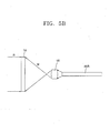
- plane wave reference light R is incident on one side of a recording medium 18 on which a hologram is recorded, and object light M is incident on the opposite side thereof.
- the object light M passes through the optical fiber 20R and the secondary focusing lens 15, is incident on the recording medium 18, and precisely records a hologram. Thereafter, a chemical development process is performed on the recording medium 18, thereby completing a holographic optical element.
- the illumination system 10R employs a spherical concave mirror 17 instead of the holographic optical element 16 as the optical path conversion unit.
- Light beams incident from the light sources 11 are reflected from the spherical concave mirror 17 to the secondary focusing lens 15 at a side where the light sources 11 are disposed and converged on the first optical fiber 20R by the secondary focusing lens 15.
- the optical path conversion unit may be composed of a first focusing lens 27 or 35 with at least one convex plane and a reflective coating 29 or 37 formed on the back of the first focusing lens 27 or 35.
- the optical path conversion unit may be composed of a first focusing lens 35' with one convex side and a reflective mirror 38 separated from the first focusing lens 35' by a predetermined gap t'.
- the focal length of the secondary focusing lens 15 can be adjusted by adjusting the gap t' between the first focusing lens 35' and the reflective mirror 38.
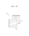
- the collimating lens array 12 may be composed of, for example, a first cylindrical convex lens 12a for compensating for the saggital plane of a light beam and a second cylindrical convex lens 12b for compensating for the tangential plane thereof, as shown in FIG. 10.
- the collimating lens array 12 may be realized as an aspherical fly-eye lens system or may be composed of a cylindrical convex lens for compensating for the saggital or tangential plane of a light beam and a spherical convex lens for performing compensation on the light beam transmitted through the cylindrical convex lens.
- This collimating lens array 12 is particularly suitable for shaping an elliptical light beam emitted from an LD into a parallel light beam.
- loss of light can be minimized by providing the second focusing lens 15 in front of the optical fiber 20R at a side where the light sources 11 are disposed.
- the volume of the optical path conversion unit increases in proportional to the number of light sources 11, and the sectional area of light flux increases as the volume of the optical path conversion unit increases. Accordingly, as the number of light sources 11 increases, a likelihood that light, which has been reflected from the optical path conversion unit and converged, goes beyond the reception angle of the optical fiber 20R also increases.
- the description concerns only the first illumination system 10R emitting a red light beam, the description is applied to the second illumination system 10G emitting a green light beam and to the third illumination system 10B emitting a blue light beam in the same manner.
- Light beams respectively emitted from the first through third illumination systems 10R, 10G, and 10B are incident on the first through third display devices 40R, 40G, and 40B, respectively, through the respective first through third optical fibers 20R, 20G, and 20B.
- the light beams are converged and converted into parallel light beams by the first through third collimating lens systems 31R, 31G, and 31B, respectively.
- Each of the first through third display devices 40R, 40G, and 40B may be a moving mirror device which forms a color image according to the on/off switching operation of a micro mirror in response to an image signal or a liquid crystal display device or liquid crystal on silicon (LCOS) which forms a color image by polarizing incident light.
- Color images formed by the first through third display devices 40R, 40G, and 40B are magnified and projected on a screen through the projection lens system 62.
- light sources emitting red, green, and blue color light beams are provided in independent structures, and three color light beams travelling different optical paths are combined by an optical combination unit, thereby forming a color image.
- light sources emitting red, green, and blue color light beams may be arranged in an array to form a single illumination system.
- the light sources can be arranged in a repeating pattern of a red light source, a green light source, and a blue light source or a group of several red light sources, a group of several green light sources, and a group of blue light sources.
- a color image can be formed using a single-chip liquid crystal display device by sequentially performing on/off control on the light sources emitting red, green, and blue light beams.
- a projection display device employing an illumination system includes a light source 70 including a plurality of small light emitters emitting red, green, and blue light beams in an array structure; an optical path conversion unit 75 for reflecting light of a predetermined wavelength emitted from the light source 70 toward the light source 70; and a secondary focusing lens 76 disposed at a side where the light source 70 is positioned for secondarily converging light which has been reflected and converged by the optical path conversion unit 75.
- the light source 70 has an array structure in which light emitters 70R, 70G, and 70B respectively emitting red, green, and blue light beams are sequentially and repeatedly arranged. The light emitters 70R, 70G, and 70B are sequentially turned on and off for light emission.
- the display device 82 may be a transmissive or reflective type, but a reflective type is used in the second embodiment of a projection display device according to the present invention.
- the display device 82 is an image forming device, such as a digital micro-mirror device (DMD), a reflective LCOS, or a transmissive LCD.
- the optical path could propagate through it and straight through the projection lens (not shown).
- the light sources are then modulated by the data with on/off signals of pixels in LCD.
- light emitters emitting red, green, and blue light beams are arranged in an array structure to form a light source, thereby simplifying the structure of an illumination system and reducing the volume thereof.
- the optical path conversion unit 75 may be composed of the Fresnel lens 13 and the reflective mirror 14, may be realized as a holographic optical element 16 or a spherical concave mirror 17, or may be composed of the focusing lens 27, 35, or 35' and the reflective coating 29 or 37 or the reflective mirror 38.
- an array of LEDs or LDs is used as a light source so that noise and heat generated when a conventional lamp light source is used can be prevented from being generated, and the life span of a light source can be greatly increased.
- harmful ultraviolet or infrared rays are not emitted in the present invention. Since a Fresnel lens or holographic optical elements are used, volume and manufacturing cost can be reduced.
- a light source is reflected back toward the light source through an optical path conversion unit so that the volumes of an illumination system and the volume of a projection display device can be greatly reduced to be compact.
- An optical fiber and a collimating lens array are used, thereby reducing optical loss.
- the elliptical light can be shaped into a high power spherical light using an optical fiber.
Landscapes
- Physics & Mathematics (AREA)
- General Physics & Mathematics (AREA)
- Engineering & Computer Science (AREA)
- Multimedia (AREA)
- Signal Processing (AREA)
- Optics & Photonics (AREA)
- Projection Apparatus (AREA)
- Liquid Crystal (AREA)
Applications Claiming Priority (2)
| Application Number | Priority Date | Filing Date | Title |
|---|---|---|---|
| KR2002005879 | 2002-02-01 | ||
| KR10-2002-0005879A KR100450815B1 (ko) | 2002-02-01 | 2002-02-01 | 조명계 및 이를 채용한 프로젝션 디스플레이 장치 |
Publications (3)
| Publication Number | Publication Date |
|---|---|
| EP1333308A2 true EP1333308A2 (de) | 2003-08-06 |
| EP1333308A3 EP1333308A3 (de) | 2004-04-14 |
| EP1333308B1 EP1333308B1 (de) | 2007-06-13 |
Family
ID=19719038
Family Applications (1)
| Application Number | Title | Priority Date | Filing Date |
|---|---|---|---|
| EP03250557A Expired - Lifetime EP1333308B1 (de) | 2002-02-01 | 2003-01-30 | Kompaktes Beleuchtungssystem und damit versehene Projektionsanzeigevorrichtung |
Country Status (5)
| Country | Link |
|---|---|
| US (1) | US6902310B2 (de) |
| EP (1) | EP1333308B1 (de) |
| JP (1) | JP4115851B2 (de) |
| KR (1) | KR100450815B1 (de) |
| DE (1) | DE60314306T2 (de) |
Cited By (9)
| Publication number | Priority date | Publication date | Assignee | Title |
|---|---|---|---|---|
| WO2006027621A3 (en) * | 2004-09-11 | 2006-06-08 | Power Projector Ltd | Light engine for projection application |
| WO2007138576A1 (en) * | 2006-05-25 | 2007-12-06 | Mirage Innovations Ltd. | Illumination system with optical integrator for an image projector |
| US7492512B2 (en) | 2004-07-23 | 2009-02-17 | Mirage International Ltd. | Wide field-of-view binocular device, system and kit |
| US7499216B2 (en) | 2004-07-23 | 2009-03-03 | Mirage Innovations Ltd. | Wide field-of-view binocular device |
| US7573640B2 (en) | 2005-04-04 | 2009-08-11 | Mirage Innovations Ltd. | Multi-plane optical apparatus |
| US7625882B2 (en) | 2003-05-27 | 2009-12-01 | Vascular Biogenics Ltd. | Oxidized lipids and uses thereof in the treatment of inflammatory diseases and disorders |
| USRE42992E1 (en) | 2003-02-19 | 2011-12-06 | Mirage Innovations Ltd. | Chromatic planar optic display system |
| CN103424973A (zh) * | 2012-05-18 | 2013-12-04 | 株式会社理光 | 光源装置以及图像投影装置以及显示装置 |
| EP2698661A1 (de) * | 2012-08-16 | 2014-02-19 | Ricoh Company, Ltd. | Beleuchtungslichterzeugungsvorrichtung |
Families Citing this family (46)
| Publication number | Priority date | Publication date | Assignee | Title |
|---|---|---|---|---|
| US8071740B2 (en) | 2000-11-17 | 2011-12-06 | Vascular Biogenics Ltd. | Promoters exhibiting endothelial cell specificity and methods of using same for regulation of angiogenesis |
| CN100506284C (zh) | 2001-10-19 | 2009-07-01 | 脉管生物生长有限公司 | 多核苷酸构建体、药物组合物以及靶向的下调血管生成和抗癌的治疗方法 |
| JP3661688B2 (ja) * | 2002-03-26 | 2005-06-15 | セイコーエプソン株式会社 | 照明装置 |
| RU2257511C2 (ru) * | 2003-08-19 | 2005-07-27 | Марков Валерий Николаевич | Многоцелевой оптический излучатель |
| DE10358053A1 (de) * | 2003-12-05 | 2005-07-14 | Siemens Ag | Lichtsignal |
| JP4013928B2 (ja) * | 2004-07-15 | 2007-11-28 | セイコーエプソン株式会社 | 照明装置、非球面レンズの設計方法、非球面レンズ及びプロジェクタ |
| KR100677551B1 (ko) * | 2005-01-05 | 2007-02-02 | 삼성전자주식회사 | Led 패키지, 조명계 및 이를 채용한 프로젝션 시스템 |
| US9128519B1 (en) | 2005-04-15 | 2015-09-08 | Intellectual Ventures Holding 67 Llc | Method and system for state-based control of objects |
| DE112006001819T5 (de) | 2005-07-08 | 2008-06-19 | Electro Scientific Industries, Inc., Portland | Erreichen von konvergenten Lichtstrahlen, die von einer planaren Anordnung von Lichtquellen emittiert werden |
| FR2895526A1 (fr) * | 2005-12-22 | 2007-06-29 | Thomson Licensing Sas | Systeme de retro-eclairage pour panneau d'affichage a cristal liquide et dispositif d'affichage correspondant |
| WO2007115432A1 (fr) * | 2006-04-10 | 2007-10-18 | Renyong Ma | Dispositif collecteur de lumière de diodes optiques |
| JP4963925B2 (ja) * | 2006-10-13 | 2012-06-27 | 三菱電機株式会社 | レーザ光源装置及び映像表示装置 |
| JP2008268271A (ja) * | 2007-04-16 | 2008-11-06 | Mitsubishi Electric Corp | 投写型表示装置 |
| KR101141087B1 (ko) | 2007-09-14 | 2012-07-12 | 인텔렉츄얼 벤처스 홀딩 67 엘엘씨 | 제스처-기반 사용자 상호작용의 프로세싱 |
| US8950900B2 (en) | 2007-10-25 | 2015-02-10 | Martin A. Stuart | Laser energy source device |
| CA2703750C (en) * | 2007-10-25 | 2017-04-04 | Martin A. Stuart | Laser energy source device and method |
| US8159682B2 (en) | 2007-11-12 | 2012-04-17 | Intellectual Ventures Holding 67 Llc | Lens system |
| CN101452192B (zh) * | 2007-12-04 | 2010-09-08 | 深圳Tcl新技术有限公司 | 照明系统及其在视频显示单元中运行的方法 |
| CN101453659B (zh) * | 2007-12-04 | 2010-12-29 | 深圳Tcl新技术有限公司 | 照明系统及其在视频显示单元中运行的方法 |
| CN101451674B (zh) * | 2007-12-04 | 2011-01-19 | 深圳Tcl新技术有限公司 | 照明系统及其在视频显示单元中运行的方法 |
| CN101453620A (zh) * | 2007-12-04 | 2009-06-10 | 深圳Tcl新技术有限公司 | 提供热门节目的方法及电子装置 |
| CN101469829A (zh) * | 2007-12-25 | 2009-07-01 | 深圳Tcl新技术有限公司 | 照明系统及其运行方法 |
| CN101498404A (zh) * | 2008-02-03 | 2009-08-05 | 深圳Tcl新技术有限公司 | 照明系统及其在视频显示单元中的运行方法 |
| US20100039500A1 (en) * | 2008-02-15 | 2010-02-18 | Matthew Bell | Self-Contained 3D Vision System Utilizing Stereo Camera and Patterned Illuminator |
| WO2009110081A1 (ja) * | 2008-03-06 | 2009-09-11 | Necディスプレイソリューションズ株式会社 | 投光光学系、及びこれを用いた投写型表示装置 |
| US8259163B2 (en) | 2008-03-07 | 2012-09-04 | Intellectual Ventures Holding 67 Llc | Display with built in 3D sensing |
| US8595218B2 (en) | 2008-06-12 | 2013-11-26 | Intellectual Ventures Holding 67 Llc | Interactive display management systems and methods |
| US20100097802A1 (en) * | 2008-10-20 | 2010-04-22 | Robe Lighting S.R.O. | Light collection system for an led luminaire |
| US8408772B2 (en) * | 2009-02-13 | 2013-04-02 | Excelitas Technologies LED Solutions, Inc. | LED illumination device |
| RU2579746C2 (ru) * | 2009-07-24 | 2016-04-10 | Конинклейке Филипс Электроникс Н.В. | Управляемая осветительная система |
| JP2012230321A (ja) * | 2011-04-27 | 2012-11-22 | Hitachi Media Electoronics Co Ltd | 走査型画像表示装置 |
| WO2013118272A1 (ja) * | 2012-02-09 | 2013-08-15 | Necディスプレイソリューションズ株式会社 | 照明光学系および投写型表示装置 |
| CN104678692B (zh) * | 2012-03-05 | 2016-06-08 | 海信集团有限公司 | 光源装置、光源产生方法及包含光源装置的激光投影机 |
| CN103365052A (zh) * | 2012-04-11 | 2013-10-23 | 鸿富锦精密工业(深圳)有限公司 | 投影机光源结构 |
| BR112014026322A2 (pt) * | 2012-04-26 | 2017-06-27 | Koninklijke Philips Nv | dispositivo laser em estado sólido bombeado opticamente |
| US9625800B2 (en) | 2012-11-06 | 2017-04-18 | Sony Corporation | Light source, light source apparatus, and image display apparatus to facilitate cooling and handling of the light source |
| JP6236811B2 (ja) * | 2013-03-14 | 2017-11-29 | 株式会社リコー | 光源ユニット並びに照明装置及び画像投射装置 |
| TWI493275B (zh) | 2013-04-20 | 2015-07-21 | Appotronics China Corp | 一種發光裝置及投影系統 |
| WO2015029517A1 (ja) * | 2013-08-27 | 2015-03-05 | 三菱重工業株式会社 | 工作機械 |
| PL410162A1 (pl) * | 2014-11-17 | 2016-05-23 | Wojskowa Akademia Techniczna | Oświetlacz LED z wyjściem światłowodowym |
| CN104680947A (zh) | 2015-02-15 | 2015-06-03 | 北京环宇蓝博科技有限公司 | Led屏幕消除莫尔条纹并提高填充系数的装置及方法 |
| EP3057082B1 (de) | 2015-02-15 | 2019-10-09 | Beijing Universal Lanbo Technology Co., Ltd. | Led-bildschirmabdeckungen und led-anzeigen |
| CN107515508A (zh) * | 2016-06-15 | 2017-12-26 | 江苏艾洛维显示科技股份有限公司 | 平行光路分体式投影机的光纤连接架构 |
| CN106444255A (zh) * | 2016-12-27 | 2017-02-22 | 海信集团有限公司 | 激光投影设备及其激光光源 |
| CN106773482A (zh) * | 2016-12-27 | 2017-05-31 | 海信集团有限公司 | 激光投影设备及其激光光源 |
| US11402617B2 (en) | 2018-07-12 | 2022-08-02 | Clark Wagner | System and method for generating white light for projectors |
Family Cites Families (19)
| Publication number | Priority date | Publication date | Assignee | Title |
|---|---|---|---|---|
| US3525566A (en) * | 1968-07-24 | 1970-08-25 | Gerald Altman | Projection devices and graphic materials therefor |
| US4448504A (en) | 1981-11-18 | 1984-05-15 | Industrial Electronic Engineers, Inc. | Rear end projection system employing aspherical lenses |
| GB8415128D0 (en) * | 1984-06-14 | 1984-07-18 | Chaimowicz J C A | Optical displacement sensors |
| US4979170A (en) * | 1988-01-19 | 1990-12-18 | Qualcomm, Inc. | Alternating sequential half duplex communication system |
| JPH05150190A (ja) * | 1991-12-02 | 1993-06-18 | Nippon Avionics Co Ltd | 直線偏光変換装置 |
| JPH0772419A (ja) * | 1993-06-14 | 1995-03-17 | Nikon Corp | 照明光学系 |
| US6310689B1 (en) * | 1996-08-23 | 2001-10-30 | Asahi Kogaku Kogyo Kabushiki Kaisha | Pattern reading apparatus |
| US5864390A (en) * | 1996-08-28 | 1999-01-26 | Polaroid Corporation | Optical system for use in a photographic printer |
| DE19718933A1 (de) * | 1997-04-28 | 1998-10-29 | Bernd Dr Ozygus | Fokussieroptik zur Strahlformung von Laserdiodenbarren zum Pumpen von Multipath-Moden |
| WO1999049358A1 (en) * | 1998-03-26 | 1999-09-30 | Mitsubishi Denki Kabushiki Kaisha | Image display and light-emitting device |
| JPH11327046A (ja) * | 1998-05-07 | 1999-11-26 | Kajima Corp | 投影器用の投光システム |
| EP1056971A1 (de) * | 1998-12-17 | 2000-12-06 | Koninklijke Philips Electronics N.V. | Lichtmachine |
| JP2000231344A (ja) * | 1999-02-10 | 2000-08-22 | Toshiba Corp | 投写型表示装置の照明装置 |
| JP2001042433A (ja) * | 1999-06-08 | 2001-02-16 | Karlheinz Strobl | 高性能光エンジンシステム、その構成要素、並びにその製造方法 |
| US6280054B1 (en) * | 1999-07-02 | 2001-08-28 | Zight Corporation | Image generator having an improved illumination system |
| JP2001215501A (ja) | 2000-02-02 | 2001-08-10 | Fuji Photo Film Co Ltd | 照明装置および液晶表示装置 |
| KR20010091471A (ko) * | 2000-03-15 | 2001-10-23 | 박호식 | 인터넷 무인경비시스템 구축 및 지원 s/w와 이를 이용한이-비즈니스 모델 |
| JP2001343706A (ja) * | 2000-05-31 | 2001-12-14 | Sony Corp | 映像表示装置 |
| US6741351B2 (en) * | 2001-06-07 | 2004-05-25 | Koninklijke Philips Electronics N.V. | LED luminaire with light sensor configurations for optical feedback |
-
2002
- 2002-02-01 KR KR10-2002-0005879A patent/KR100450815B1/ko not_active Expired - Fee Related
-
2003
- 2003-01-30 US US10/353,948 patent/US6902310B2/en not_active Expired - Fee Related
- 2003-01-30 DE DE60314306T patent/DE60314306T2/de not_active Expired - Lifetime
- 2003-01-30 EP EP03250557A patent/EP1333308B1/de not_active Expired - Lifetime
- 2003-02-03 JP JP2003025835A patent/JP4115851B2/ja not_active Expired - Fee Related
Cited By (13)
| Publication number | Priority date | Publication date | Assignee | Title |
|---|---|---|---|---|
| US7893291B2 (en) | 2000-11-24 | 2011-02-22 | Vascular Biogenics Ltd. | Methods employing and compositions containing defined oxidized phospholipids for prevention and treatment of atherosclerosis |
| USRE42992E1 (en) | 2003-02-19 | 2011-12-06 | Mirage Innovations Ltd. | Chromatic planar optic display system |
| US7625882B2 (en) | 2003-05-27 | 2009-12-01 | Vascular Biogenics Ltd. | Oxidized lipids and uses thereof in the treatment of inflammatory diseases and disorders |
| US7902176B2 (en) | 2003-05-27 | 2011-03-08 | Vascular Biogenics Ltd. | Oxidized lipids and uses thereof in the treatment of inflammatory diseases and disorders |
| US7973023B2 (en) | 2003-05-27 | 2011-07-05 | Vascular Biogenics Ltd. | Oxidized lipids and uses thereof in the treatment of inflammatory diseases and disorders |
| US7492512B2 (en) | 2004-07-23 | 2009-02-17 | Mirage International Ltd. | Wide field-of-view binocular device, system and kit |
| US7499216B2 (en) | 2004-07-23 | 2009-03-03 | Mirage Innovations Ltd. | Wide field-of-view binocular device |
| WO2006027621A3 (en) * | 2004-09-11 | 2006-06-08 | Power Projector Ltd | Light engine for projection application |
| US7573640B2 (en) | 2005-04-04 | 2009-08-11 | Mirage Innovations Ltd. | Multi-plane optical apparatus |
| WO2007138576A1 (en) * | 2006-05-25 | 2007-12-06 | Mirage Innovations Ltd. | Illumination system with optical integrator for an image projector |
| CN103424973A (zh) * | 2012-05-18 | 2013-12-04 | 株式会社理光 | 光源装置以及图像投影装置以及显示装置 |
| EP2698661A1 (de) * | 2012-08-16 | 2014-02-19 | Ricoh Company, Ltd. | Beleuchtungslichterzeugungsvorrichtung |
| US9121570B2 (en) | 2012-08-16 | 2015-09-01 | Ricoh Company, Ltd. | Illumination light generation apparatus |
Also Published As
| Publication number | Publication date |
|---|---|
| KR100450815B1 (ko) | 2004-10-01 |
| US6902310B2 (en) | 2005-06-07 |
| JP2003248270A (ja) | 2003-09-05 |
| DE60314306T2 (de) | 2008-02-14 |
| US20030147255A1 (en) | 2003-08-07 |
| KR20030065846A (ko) | 2003-08-09 |
| JP4115851B2 (ja) | 2008-07-09 |
| EP1333308B1 (de) | 2007-06-13 |
| EP1333308A3 (de) | 2004-04-14 |
| DE60314306D1 (de) | 2007-07-26 |
Similar Documents
| Publication | Publication Date | Title |
|---|---|---|
| EP1333308B1 (de) | Kompaktes Beleuchtungssystem und damit versehene Projektionsanzeigevorrichtung | |
| US6491398B2 (en) | Video projector | |
| US7448758B2 (en) | Illumination unit and projection type image display apparatus employing the same | |
| US6499863B2 (en) | Combining two lamps for use with a rod integrator projection system | |
| US7331680B2 (en) | Illumination unit and projection type image display apparatus employing the same | |
| US20050063196A1 (en) | Light pipe based projection engine | |
| JP3264916B2 (ja) | カラープロジェクタ | |
| KR100597820B1 (ko) | 광학장치와광학장치를구비한표시장치 | |
| US7020379B2 (en) | Illumination optical system including light separation/integration device having diffraction device and image display apparatus including the illumination optical system | |
| US7648244B2 (en) | Illuminating unit and projection-type image display apparatus employing the same | |
| KR100381050B1 (ko) | 액정 프로젝터의 광학계 | |
| KR20070115882A (ko) | 에텐듀 효율이 높은 복수 광원 결합기 | |
| WO2011103807A1 (zh) | 图像投影系统及其光路合成器 | |
| JP5097042B2 (ja) | 照明光学装置及びそれを用いた投写型表示装置 | |
| JPH1082959A (ja) | 投写型映像表示装置 | |
| US12015881B2 (en) | Light source apparatus including a microlens array, projector including a microlens array, microlens array, and light source control method for the light source apparatus including the microlens array | |
| CN211086897U (zh) | 投影系统 | |
| US8182101B2 (en) | Illumination optical system having the longest air interspace distance between a first and a second optical unit where a specific condition is satisfied for the optical system | |
| JPH0933881A (ja) | 液晶ビデオプロジェクタ | |
| KR100359728B1 (ko) | 액정 프로젝터의 광학 장치 | |
| JP2021005060A (ja) | 光源装置およびこれを備える画像投射装置 | |
| JP2012252102A (ja) | 投写型表示装置 | |
| JP2008292673A (ja) | 色分離合成装置及びそれを用いた投射型表示装置 | |
| KR20050078290A (ko) | 프로젝션 시스템 | |
| JP2002365618A (ja) | 液晶ライトバルブおよび液晶プロジェクタ |
Legal Events
| Date | Code | Title | Description |
|---|---|---|---|
| PUAI | Public reference made under article 153(3) epc to a published international application that has entered the european phase |
Free format text: ORIGINAL CODE: 0009012 |
|
| AK | Designated contracting states |
Designated state(s): AT BE BG CH CY CZ DE DK EE ES FI FR GB GR HU IE IT LI LU MC NL PT SE SI SK TR |
|
| AX | Request for extension of the european patent |
Extension state: AL LT LV MK RO |
|
| PUAL | Search report despatched |
Free format text: ORIGINAL CODE: 0009013 |
|
| AK | Designated contracting states |
Kind code of ref document: A3 Designated state(s): AT BE BG CH CY CZ DE DK EE ES FI FR GB GR HU IE IT LI LU MC NL PT SE SI SK TR |
|
| AX | Request for extension of the european patent |
Extension state: AL LT LV MK RO |
|
| RIC1 | Information provided on ipc code assigned before grant |
Ipc: 7G 02F 1/1335 B Ipc: 7H 04N 9/31 B Ipc: 7G 02B 27/00 A Ipc: 7G 02B 6/00 B Ipc: 7G 03B 21/20 B |
|
| 17P | Request for examination filed |
Effective date: 20040818 |
|
| 17Q | First examination report despatched |
Effective date: 20040923 |
|
| AKX | Designation fees paid |
Designated state(s): DE FR GB |
|
| RIC1 | Information provided on ipc code assigned before grant |
Ipc: H04N 9/31 20060101ALI20061115BHEP Ipc: F21K 7/00 20060101ALI20061115BHEP Ipc: G02F 1/1335 20060101ALI20061115BHEP Ipc: G03B 21/20 20060101ALI20061115BHEP Ipc: G02B 27/00 20060101AFI20061115BHEP Ipc: G02B 6/00 20060101ALI20061115BHEP |
|
| GRAP | Despatch of communication of intention to grant a patent |
Free format text: ORIGINAL CODE: EPIDOSNIGR1 |
|
| GRAS | Grant fee paid |
Free format text: ORIGINAL CODE: EPIDOSNIGR3 |
|
| GRAA | (expected) grant |
Free format text: ORIGINAL CODE: 0009210 |
|
| AK | Designated contracting states |
Kind code of ref document: B1 Designated state(s): DE FR GB |
|
| REG | Reference to a national code |
Ref country code: GB Ref legal event code: FG4D |
|
| REF | Corresponds to: |
Ref document number: 60314306 Country of ref document: DE Date of ref document: 20070726 Kind code of ref document: P |
|
| ET | Fr: translation filed | ||
| PLBE | No opposition filed within time limit |
Free format text: ORIGINAL CODE: 0009261 |
|
| STAA | Information on the status of an ep patent application or granted ep patent |
Free format text: STATUS: NO OPPOSITION FILED WITHIN TIME LIMIT |
|
| 26N | No opposition filed |
Effective date: 20080314 |
|
| PGFP | Annual fee paid to national office [announced via postgrant information from national office to epo] |
Ref country code: GB Payment date: 20131220 Year of fee payment: 12 |
|
| PGFP | Annual fee paid to national office [announced via postgrant information from national office to epo] |
Ref country code: DE Payment date: 20131220 Year of fee payment: 12 |
|
| PGFP | Annual fee paid to national office [announced via postgrant information from national office to epo] |
Ref country code: FR Payment date: 20131220 Year of fee payment: 12 |
|
| REG | Reference to a national code |
Ref country code: DE Ref legal event code: R119 Ref document number: 60314306 Country of ref document: DE |
|
| GBPC | Gb: european patent ceased through non-payment of renewal fee |
Effective date: 20150130 |
|
| PG25 | Lapsed in a contracting state [announced via postgrant information from national office to epo] |
Ref country code: GB Free format text: LAPSE BECAUSE OF NON-PAYMENT OF DUE FEES Effective date: 20150130 Ref country code: DE Free format text: LAPSE BECAUSE OF NON-PAYMENT OF DUE FEES Effective date: 20150801 |
|
| REG | Reference to a national code |
Ref country code: FR Ref legal event code: ST Effective date: 20150930 |
|
| PG25 | Lapsed in a contracting state [announced via postgrant information from national office to epo] |
Ref country code: FR Free format text: LAPSE BECAUSE OF NON-PAYMENT OF DUE FEES Effective date: 20150202 |