EP1333710A2 - Méthode und appareil pour absorber l' énergie thermique - Google Patents
Méthode und appareil pour absorber l' énergie thermique Download PDFInfo
- Publication number
- EP1333710A2 EP1333710A2 EP03001362A EP03001362A EP1333710A2 EP 1333710 A2 EP1333710 A2 EP 1333710A2 EP 03001362 A EP03001362 A EP 03001362A EP 03001362 A EP03001362 A EP 03001362A EP 1333710 A2 EP1333710 A2 EP 1333710A2
- Authority
- EP
- European Patent Office
- Prior art keywords
- thermal energy
- electronic component
- absorbing material
- energy absorbing
- thermal
- Prior art date
- Legal status (The legal status is an assumption and is not a legal conclusion. Google has not performed a legal analysis and makes no representation as to the accuracy of the status listed.)
- Granted
Links
Images
Classifications
-
- H—ELECTRICITY
- H10—SEMICONDUCTOR DEVICES; ELECTRIC SOLID-STATE DEVICES NOT OTHERWISE PROVIDED FOR
- H10W—GENERIC PACKAGES, INTERCONNECTIONS, CONNECTORS OR OTHER CONSTRUCTIONAL DETAILS OF DEVICES COVERED BY CLASS H10
- H10W40/00—Arrangements for thermal protection or thermal control
- H10W40/20—Arrangements for cooling
- H10W40/25—Arrangements for cooling characterised by their materials
- H10W40/257—Arrangements for cooling characterised by their materials having a heterogeneous or anisotropic structure, e.g. powder or fibres in a matrix, wire mesh or porous structures
-
- H—ELECTRICITY
- H10—SEMICONDUCTOR DEVICES; ELECTRIC SOLID-STATE DEVICES NOT OTHERWISE PROVIDED FOR
- H10N—ELECTRIC SOLID-STATE DEVICES NOT OTHERWISE PROVIDED FOR
- H10N10/00—Thermoelectric devices comprising a junction of dissimilar materials, i.e. devices exhibiting Seebeck or Peltier effects
-
- H—ELECTRICITY
- H10—SEMICONDUCTOR DEVICES; ELECTRIC SOLID-STATE DEVICES NOT OTHERWISE PROVIDED FOR
- H10W—GENERIC PACKAGES, INTERCONNECTIONS, CONNECTORS OR OTHER CONSTRUCTIONAL DETAILS OF DEVICES COVERED BY CLASS H10
- H10W40/00—Arrangements for thermal protection or thermal control
- H10W40/70—Fillings or auxiliary members in containers or in encapsulations for thermal protection or control
- H10W40/73—Fillings or auxiliary members in containers or in encapsulations for thermal protection or control for cooling by change of state
-
- H—ELECTRICITY
- H10—SEMICONDUCTOR DEVICES; ELECTRIC SOLID-STATE DEVICES NOT OTHERWISE PROVIDED FOR
- H10W—GENERIC PACKAGES, INTERCONNECTIONS, CONNECTORS OR OTHER CONSTRUCTIONAL DETAILS OF DEVICES COVERED BY CLASS H10
- H10W40/00—Arrangements for thermal protection or thermal control
- H10W40/70—Fillings or auxiliary members in containers or in encapsulations for thermal protection or control
- H10W40/73—Fillings or auxiliary members in containers or in encapsulations for thermal protection or control for cooling by change of state
- H10W40/735—Fillings or auxiliary members in containers or in encapsulations for thermal protection or control for cooling by change of state by melting or evaporation of solids
Definitions
- the present invention relates generally to absorbing thermal energy to cool to a thermal load, such as thermal energy generated by electronic components.
- Electronics such as RF sensor transmit/receive (T/R) units, can be relatively inefficient (15-25 %) at converting electrical energy to radiated power and as a result generate waste heat. If there is insufficient thermal mass to absorb this waste heat, mounting surface and junction temperatures of electronic components can rise with consequent component failure. Additionally, waste heat in general can contribute to degradation of materials resulting in reduced lifetime and device failure. Moreover, thermal management solutions can limit device miniaturization.
- an apparatus for absorbing thermal energy has an electronic component, a support structure for the electronic component having a first set of surfaces defining an interior volume containing a plurality of secondary surfaces, and a thermal energy absorbing material integrated within the interior volume, in contact with at least a portion of the secondary surfaces to form a composite structure.
- the thermal energy absorbing material is in operative thermal communication with the electronic component such that at least a portion of the thermal energy generated by the electronic component flows, via the support structure, into the thermal energy absorbing material.
- Exemplary methods are disclosed for controlling a temperature of an electronic component, wherein an electronic component is mounted on a support structure in thermal communication with a thermal energy absorbing material integrated into an interior volume of the support structure, at least a portion of a thermal load from the electronic component is transported to the thermal energy absorbing material, and the portion of the thermal load is absorbed with the thermal energy absorbing material while undergoing an endothermic reaction during a phase change of the material, such that a temperature of the electronic component is maintained below a mounting surface temperature.
- the thermal energy absorbing material can be selected to have a phase change temperature less than the mounting surface temperature.
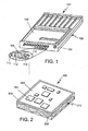
- Figure 1 is an exemplary embodiment of an apparatus for absorbing thermal energy.
- Figure 2 is another exemplary embodiment of an apparatus for absorbing thermal energy.
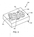
- Figure 3 is a cut-away perspective of an exemplary embodiment of a support structure with an integrated thermal energy absorbing material.
- the present invention is directed to an apparatus for absorbing thermal energy.
- An exemplary apparatus for absorbing thermal energy is illustrated in FIG. 1 as an apparatus 100.
- the FIG. 1 apparatus 100 includes an electronic component 102, a support structure 104 for the electronic component 102, and a thermal energy absorbing material 106.
- the support structure 104 has a first set of surfaces 108 defining an interior volume 110 containing a plurality of secondary surfaces 112.
- the thermal energy absorbing material 106 is integrated within the interior volume 110 of the support structure 104 in contact with at least a portion of the secondary surfaces 112 to form a composite structure.
- the thermal energy absorbing material 106 is in operative thermal communication with the electronic component 102 such that at least a portion of the thermal energy generated by the electronic component flows, via the support structure 104, into the thermal energy absorbing material 106.
- FIG. 2 also shows an exemplary embodiment of an apparatus for absorbing thermal energy.
- a circuit card 202 with electronic components 204 is in direct contact with a support structure 206 having a thermal energy absorbing material 208 integrated within an interior volume 210.
- the electronic component is one or more of a monolithic millimeterwave integrated circuit (MMIC), a radio frequency (RF) power amplifier, an electronic chip, a circuit card, and a thermal battery.
- MMIC millimeterwave integrated circuit
- RF radio frequency
- the electronic component can be an element in a electronic assembly.
- the electronic component can be an element in an inertial measurement unit, a radiating unit, a transmit/receive unit or a thermal reference source.
- the electronic component is supported by a support structure.
- the structural support of the thermal energy absorbing apparatus is formed of material that can be a thermal conductor between the substrate with the integrated thermal energy absorbing material and the electronic component supported thereby.
- the electronic component is affixed to the structural support, is surface mounted to the support structure, is pressure mounted to the support structure, or is otherwise placed in abutting contacting to the support structures such that the electronic component and the support structure are in thermal contact.
- the thermal energy absorbing apparatus sees at least a portion of the waste heat generated by the electronic component when the electronic is in operation.
- the support structure can be formed from a metal-based or ceramic-based material.
- the support structure can be formed from metal-based materials, such as aluminum, foam aluminum, or copper, or formed from ceramic-based material, such as silicon-carbide-aluminum.
- the interior volume of the support structure can be continuously connected.
- the support structure can also have an interior volume composed of a plurality of discrete interior volumes, such as a honeycomb arrangement, or can be a permeable sponge-like structure.
- a suitable support structure is a foam metal with an interior volume in the form of a continuously connected, duodecahedronal shaped open-cell geometry.
- Examples of duodecahedronal shaped open-cell geometry foam metals include DUOCEL® materials available from ERG Materials of Oakland, California.
- Duocelan aluminum foam metal with a continuously connected, duodecahedronal shaped open-cell geometry has an interior volume, density and cell size that are independently variable, with available density ranges from 3% to 50% relative to the solid base metal and cell density of 5, 10, 20 and 40 pores per linear inch.
- duocelan aluminum foam can be cut, turned, milled, drilled, rolled and finished to normal tolerances just like the base aluminum material.
- duocelan aluminum foam can form an integral metal-to-metal bond.
- a duocelan geometry can be practiced in other suitable support structure material, such as vitreous carbon and ceramic-based materials.
- FIG. 3 shows the support structure presented in a cutaway perspective with an integrated thermal energy absorbing material.
- the support structure 300 has a first set of surfaces 302, which define an interior volume 304.
- the interior volume 304 contains a plurality of secondary surfaces 306 and the thermal energy absorbing material 308 is integrated into the interior volume 304.
- the thermal energy absorbing material can be integrated into the support structure of the thermal energy absorbing apparatus by any suitable means.
- the thermal energy absorbing material can be impregnated into the support structure under pressure or vacuum (e.g., injected by a carrier gas, vacuum dragged, and so forth).
- the thermal energy absorbing material can have its temperature changed to undergo a phase change to a malleable state (e.g., changed to a liquid or a viscous condition) and then poured, injected, or encapsulated within the interior volume.
- a foam aluminum support structure can have a thermal energy absorbing material integrated within the interior volume.
- This combination provides structural support for the electronic component, (e.g., Microwave Power Amplifier (MPA), RF transmit/receive element, and so forth), while supplementing the thermal capacity of the structural support with a thermal energy absorbing material.
- Waste heat from the electronic component can be transported via the foam aluminum structure to the thermal energy absorbing material, which absorbs the thermal energy while its temperature rises to the phase change temperature, (e.g., rises to the solid-to-liquid phase change temperature).
- the thermal energy continues to be absorbed by the thermal energy absorbing material while the phase change occurs with the accompanying endothermic reaction.
- the phase change temperature and thermal resistance between the electronic component and thermal energy absorbing material fix the temperature of the electronic component, at least during the phase change.
- the thermal energy absorbing material can make available additional thermal mass for rapid waste heat absorption.
- waste heat generated from the electrical load can be absorbed by the phase change material both to increase the temperature of the phase change material as well as to cause the phase change and to thereby limit the temperature transient caused by operation of the electrical load.
- the increased thermal mass in the form of a phase change material incorporated into the support structure can minimize the impact on the electrical load, passive device, electrical conductor and other associated electronics and electrical circuitry and reduce the incidence of heat related component failure.
- An exemplary thermal energy absorbing apparatus has an integrated support structure and thermal energy absorbing material.
- a support structure for the transmit/receive electronics and/or a support structure for the thermal management structure can be impregnated with a material that has a high specific heat capacity and/or that undergoes a phase change in the temperature range associated with the heat dissipated by the electronic component.
- the electronic component generates waste heat.
- the thermal energy absorbing material absorbs the waste heat thermally conducted from the electronic component to the support structure and raises the temperature of the thermal energy absorbing material. If there is sufficient waste heat, the associated temperature increase in the thermal energy absorbing material can reach the phase change temperature, at which temperature the thermal energy absorbing material remains while continuing to absorb the heat and undergoing the phase change.
- the thermal energy absorbing material can contribute to maintaining junction temperatures below critical levels during operation of the electronic component.
- the electronic components can be maintained below a maximum surface mounting or junction temperature at which dielectric breakdown, junction failure, and other debilitating failures can occur.
- a maximum surface mounting or junction temperature at which dielectric breakdown, junction failure, and other debilitating failures can occur.
- the temperature is about 90°C (e.g., ⁇ 10% or greater) and about 120°C (e.g., ⁇ 10% or greater), respectively.
- the thermal energy absorbing apparatus can operate, (for example, change phase), at or below the maximum temperature for a particular electronic component.
- An exemplary thermal energy absorbing material is a phase change material. That is, the phase change material can be any material selected from a group of materials that change phase (e.g., a transform from solid to liquid, liquid to gas, solid to gas, and/or the reverse transformations, over a narrow temperature range while absorbing (endothermic) or producing (exothermic) large amounts of heat energy). In an endothermic reaction, a portion of the absorbed heat corresponds to the absorption of the latent heat of melting or the latent heat of vaporization for a solid-liquid phase change and a liquid to gas phase change, respectively. To mitigate temperature increases of supported electronic components, the thermal energy absorbing material can be any material that undergoes an endothermic reaction within a desired temperature range of the electronic component.
- a group of materials that change phase e.g., a transform from solid to liquid, liquid to gas, solid to gas, and/or the reverse transformations, over a narrow temperature range while absorbing (endothermic) or producing (exothermic) large amounts of heat energy
- Phase change materials are operative over a wide range of temperatures and include such examples as ice (melting temperature of 32°C and heat of fusion of 144 BTU/pound) and paraffin wax (melting temperature of 126°F and heat of fusion of 63 BTU/pound).
- the general chemical formula for alkanes or paraffins is: C n H 2n+2 .
- normal-paraffins can be used, due to their higher heat storage capacity.
- Other physical properties influencing the performance of phase change materials include the solid specific heat (parameter of heat absorbed as a function of temperature in a single phase), solid and liquid thermal conductivity (parameter of heat transport within the material) and solid and liquid specific density (parameter of mass to volume).
- phase change materials can be found in several forms including granulate, powder, paste and micro-encapsulated (phase change material in small polymer spheres).
- factors to consider when selecting a phase change material include: ecologically impact; toxicity; chemical inertness to other materials; longevity; stability throughout multiple cycles; ability to be recycled; ease of handling, and narrowness of melting temperature band.
- Suitable commercial phase change materials include Rubitherm® available from Rubitherm Gmbh of Hamburg Germany, Climsel® available from Clitnator AB of Skovde, Sweden, and TEAP® available from TEAP Energy of Wangara, Australia.
- the thermal energy absorbing material can be located very near the electronic component to effectively absorb waste heat.
- the available volume can be limited due to the high-density packaging of individual electronic components (e.g., the RF transmit/receive elements, microwave power amplifiers, and so forth), that constitute the larger electronic system, (e.g., the RF transmit/receive unit, radiating unit, inertial measurement unit, thermal reference source, and so forth). Therefore, a thermal energy absorbing material with a large heat of fusion and high specific density can be used for electronic components that are densely packaged.
- a foam aluminum support structure can have a thermal energy absorbing material integrated with the interior volume.
- This combination provides structural support for the electronic component (e.g., MPA, RF transmit/receive element, and so forth), while supplementing the thermal capacity of the system.
- Waste heat from the electronic component can be transported via the foam aluminum structure to the thermal energy absorbing material, which absorbs the thermal energy while its temperature rises to the phase change temperature (e.g., rises to the solid-to-liquid phase change temperature).
- the thermal energy continues to be absorbed by the thermal energy absorbing material while the phase change occurs with the accompanying endothermic reaction.
- the phase change temperature and thermal resistance between the electronic component and phase change material fix the temperature of the electronic component, at least during the phase change.
- thermal energy absorbing material with a suitable support structure can make available additional thermal mass (e.g., the thermal energy absorbing material) for rapid electronic component waste heat absorption for short time periods and therefore contribute to maintaining surface mount and junction temperatures below levels that deleteriously impact the performance of electronic components and/or thermally degrade materials during operation of the electronic component.
- additional thermal mass e.g., the thermal energy absorbing material
- the increased thermal mass in the form of thermal energy absorbing material incorporated into the support structure can minimize and reduce the incidence of the heat related electronic component failure.
- the apparatus for absorbing thermal energy can be operatively integrated into a thermal management structure, as disclosed in commonly-owned U.S. Patent Application No. 10/107,177 entitled "INTEGRATED POWER AND COOLING ARCHITECTURE" filed March 28, 2002, the entire contents of which are hereby incorporated by reference.
- a thermal management structure as disclosed in commonly-owned U.S. Patent Application No. 10/107,177 entitled "INTEGRATED POWER AND COOLING ARCHITECTURE" filed March 28, 2002, the entire contents of which are hereby incorporated by reference.
- several MMICs and other electronic parts can be mounted to a circuit board that is structurally supported by an apparatus for absorbing thermal energy.
- the apparatus has a support structure formed from foam aluminum and a thermal energy absorbing material is integrated within the foam aluminum interior volume.
- the thermal energy absorbing material is Rubitherm RT80, a phase change material.
- the waste heat from the MMIC is transported by the foam aluminum structure and is distributed to the thermal energy absorbing material.
- the solid thermal energy absorbing material absorbs the MMIC generated heat while its temperature rises to the solid to liquid phase change temperature of 79°C.
- the MMIC generated heat continues to be absorbed while the solid changes to a liquid phase.
- the phase change temperature and thermal resistance between the MMIC and thermal energy absorbing material contribute to fix the junction temperature of the MMIC and its operating performance.
- total heat generated by the electronic components is 45 watts for 30 seconds that can be absorbed within the unit while maintaining a MMIC mounting surface temperature of no more than 95°C.
- the support structure with integrated thermal energy absorbing material has a volume of 0.40 cubic inches out of 1.42 cubic inches for the total system; the foam aluminum/thermal energy absorbing material weighs 8.65 grams out of 46.3 grams for the total system; and the thermal energy absorbing material absorbs 700 joules of heat out of total heat load of 1350 joules.
- the system's thermal mass is increased by 48.7%.
- Mounting surface temperature without the thermal energy absorbing material integrated within the interior volume of the support structure would be 102°C (thus exceeding the MMIC mounting surface temperature limit) and the use of solid aluminum for the support structure would increase the weight by 8.7 grams (the invention decreases the system weight by 16%).
- an RF transmit/receive (T/R) module is structurally supported by ERG foam aluminum.
- the T/R module can comprise heat dissipating electronic components (such as a MMIC).
- the foam aluminum has the Rubitherm RT80 phase change material integrated within the foam aluminum interior volume. The waste heat from the T/R module is transported by the foam aluminum structure and is distributed to the thermal energy absorbing material. The solid thermal energy absorbing material absorbs the generated heat while its temperature rises to the solid to liquid phase change temperature of 79°C. The generated heat continues to be absorbed while the solid changes to a liquid phase.
- the phase change temperature and thermal resistance between the MMIC and thermal energy absorbing material fix the junction temperature of the MMIC and its operating performance.
- Total power generated by the electronic components is 22.5 watts for 30 seconds that can be absorbed within the unit while maintaining a MMIC mounting surface temperature of 95°C.
- the structural foam with thermal energy absorbing material filled voids has a volume of 0.20 cubic inches out of 0.71 cubic inches for the total system.
- the foam aluminum/thermal energy absorbing material weight is 4.33 grams out of 23.2 grams for the total system.
- the thermal energy absorbing material absorbs 350 joules of heat out of 675 joules total heat load (the invention increases the system thermal mass by 48.7%).
- Mounting surface temperature without the thermal energy absorbing material integrated within the interior volume of the support structure would be 102°C (thus exceeding the MMIC mounting surface temperature limit) and the weight would increase by 8.7 grams (the invention decreases the system weight by 16%).
- a mobile phone has an electronic component, one of which might be an RF power amplifier.
- an electronic component one of which might be an RF power amplifier.
- quiescent heat dissipation is very low and is dissipated to the surrounding environment with minimal increase in overall component temperature.
- the ambient thermal energy loss rate approximates the quiescent thermal energy generation rate.
- the waste heat from the electronic components can be very high and more thermal energy is absorbed locally to the electronic components.
- the electronic component is structurally supported by foam aluminum having integrated phase change material (PCM) (e.g., paraffin wax blended with boron nitride) within the interior volume.
- PCM phase change material
- the waste heat during transmission is transported into the foam aluminum structure where it is distributed to the thermal energy absorbing material while still limiting the maximum surface mount temperature.
- the solid thermal energy absorbing material absorbs the heat while its temperature rises to the solid to liquid phase change temperature of 52.4°C. The heat continues to be absorbed while some of the solid changes phase to the liquid state.
- any liquid thermal energy absorbing material will revert to a solid by an exothermic process where excess heat is conducted and naturally dissipated to the surrounding environment.
- the exothermic process can be such that ambient losses can accommodate the thermal energy to avoid raising surface mount temperatures.
- a thermal battery provides electrical power to an electronic component, such as in a military application, an airborne platform, and so forth.
- the chemical reaction within the battery produces electrical energy and gives off large amounts of waste heat.
- the battery walls and structure supporting the required chemicals are made of foam aluminum.
- a thermal energy absorbing material such as Rubitherm RT110 PCM, is integrated with the interior volume of the foam aluminum.
- the activated battery waste heat is transported into the foam aluminum support structure where it is distributed to the thermal energy absorbing material.
- the solid thermal energy absorbing material absorbs the heat while its temperature rises to the solid to liquid phase change temperature of 110°C. The heat continues to be absorbed while the solid changes to liquid state.
- a thermal reference source maintains the temperature of a conditioned surface at ⁇ 0.1-0.5°C of a desired fixed temperature for Forward Looking Infrared (FLIR) electronic referencing to set signal gain and level.
- the TRS can use a thermal electric device (TE) to temperature condition the surface resulting in 3.5 watts of waste heat generated on the TE mounting surface (opposite the temperature conditioned surface).
- TE thermal electric device
- the surface conditioning lasts 120 seconds with long time periods (typically one hour) of quiescent, low or no heat dissipating activity.
- TE's are able to maintain a temperature-conditioned surface within ⁇ 30°C of the mounting surface temperature. Quiescent heat dissipation is naturally dissipated to the surrounding environment.
- the TE device when the TE device is temperature conditioning, the heat dissipation is very high and must be absorbed locally.
- the TE is structurally supported by foam aluminum with a thermal energy absorbing material within an interior 0.25 cubic inch volume that forms the mounting surface.
- Thermal energy absorbing material e.g., paraffin wax blended with boron nitride, is integrated within the foam aluminum interior volume.
- the waste heat is transported into the foam aluminum support structure where it is distributed to the thermal energy absorbing material.
- the solid thermal energy absorbing material absorbs the heat while its temperature rises to the solid to liquid phase change temperature of 52.4°C. The heat continues to be absorbed while some of the solid changes to liquid state.
- the TE performance, phase change temperature and thermal resistance between the TE mounting surface and thermal energy absorbing material fix the conditioned surface temperature, which may be as low as 25°C.
- any liquid phase thermal energy absorbing material will revert to a solid phase by an exothermic process where excess heat is conducted and naturally dissipated to the surrounding environment. The whole cycle can then be repeated.
- This configuration relative to an exemplary block of solid aluminum, can provide a 50% weight reduction and better TE performance.
- the temperature-conditioned surface operating point is 50°C for an aluminum block versus 25°C for the thermal energy absorbing apparatus.
- a 6-inch-by-6-inch (6x6) circuit card can operate with a very high waste heat dissipation (e.g., 18 watts) for a fixed length of time (e.g., approximately 300 seconds).
- the circuit card attached by mounting technologies, such as bonding, thermal paste, and so forth directly to a structural support, such as foam aluminum with thermal energy absorbing material integrated within the interior volume has a thickness of 0.085 inches. Waste heat from the circuit card is transported through the foam aluminum structure from a contact location and is distributed to the thermal energy absorbing material.
- the solid thermal energy absorbing material absorbs the heat and the temperature rises to the solid to liquid phase change temperature. The heat continues to be absorbed while the solid changes to liquid.
- the circuit card temperature rise will be approximately 15°C.
- a traditional method is to use a solid aluminum sheet that absorbs the heat and/or transports the heat to some ultimate heat sink has a calculated temperature rise of 41°C.
- an electronic component is mounted on a support structure in thermal communication with a thermal energy absorbing material integrated into an interior volume of the support structure. At least a portion of a thermal load from the electronic component is transported to the thermal energy absorbing material, and the portion of the thermal load is absorbed with the thermal energy absorbing material while undergoing an endothermic reaction during a phase change of the material, such that a temperature of the electronic component is maintained below a mounting surface temperature.
- the thermal energy absorbing material can be selected to have a phase change temperature less than the mounting surface temperature.
- the electronic component can be mounted directly to the support structure.
Landscapes
- Cooling Or The Like Of Electrical Apparatus (AREA)
- Cooling Or The Like Of Semiconductors Or Solid State Devices (AREA)
Applications Claiming Priority (4)
| Application Number | Priority Date | Filing Date | Title |
|---|---|---|---|
| US35092402P | 2002-01-25 | 2002-01-25 | |
| US350924P | 2002-01-25 | ||
| US10/166,202 US6621702B2 (en) | 2002-01-25 | 2002-06-11 | Method and apparatus for absorbing thermal energy |
| US166202 | 2002-06-11 |
Publications (3)
| Publication Number | Publication Date |
|---|---|
| EP1333710A2 true EP1333710A2 (fr) | 2003-08-06 |
| EP1333710A3 EP1333710A3 (fr) | 2006-04-19 |
| EP1333710B1 EP1333710B1 (fr) | 2007-12-12 |
Family
ID=26862054
Family Applications (1)
| Application Number | Title | Priority Date | Filing Date |
|---|---|---|---|
| EP03001362A Expired - Lifetime EP1333710B1 (fr) | 2002-01-25 | 2003-01-24 | Méthode und appareil pour absorber l' énergie thermique |
Country Status (3)
| Country | Link |
|---|---|
| US (1) | US6621702B2 (fr) |
| EP (1) | EP1333710B1 (fr) |
| ES (1) | ES2297059T3 (fr) |
Cited By (5)
| Publication number | Priority date | Publication date | Assignee | Title |
|---|---|---|---|---|
| EP2154462A1 (fr) * | 2008-08-13 | 2010-02-17 | BAE Systems PLC | Corps de stockage de chaleur latente |
| WO2018210950A1 (fr) * | 2017-05-16 | 2018-11-22 | Thales | Matériau thermique à haute capacité et haute conductivité, son procédé de préparation et les composants le comprenant |
| WO2019013870A1 (fr) * | 2017-07-10 | 2019-01-17 | Qualcomm Incorporated | Refroidissement d'enceinte pour gestion thermique de véhicules aériens sans pilote |
| WO2019122419A1 (fr) * | 2017-12-22 | 2019-06-27 | Thales | Materiau thermique ameliore a haute capacite et haute conductivite, son procede de preparation et composants le comprenant |
| EP4598289A1 (fr) * | 2024-02-05 | 2025-08-06 | Rockwell Collins, Inc. | Module de montage de bâti pouvant être monté sur fente configuré pour refroidir un montage de bâti électronique |
Families Citing this family (63)
| Publication number | Priority date | Publication date | Assignee | Title |
|---|---|---|---|---|
| US7312985B2 (en) * | 2002-03-08 | 2007-12-25 | Lg Electronics Inc. | Cooler of notebook personal computer and fabrication method thereof |
| US7938170B2 (en) * | 2002-09-11 | 2011-05-10 | Webasto Ag | Cold or heat accumulator and process for its manufacture |
| DE10257942A1 (de) * | 2002-12-12 | 2004-06-24 | Krauss-Maffei Wegmann Gmbh & Co. Kg | Schutzmodul zum Schutz von Objekten gegen Bedrohungen, insbesondere durch Hohlladungen |
| EP2604215B1 (fr) | 2003-02-25 | 2017-10-11 | Tria Beauty, Inc. | Appareil et procédé de traitement dermatologique inoffensif pour les yeux |
| US8709003B2 (en) | 2003-02-25 | 2014-04-29 | Tria Beauty, Inc. | Capacitive sensing method and device for detecting skin |
| US20040252454A1 (en) * | 2003-06-16 | 2004-12-16 | Auras Technology Ltd. | Laptop computer heat dissipator |
| US20060009749A1 (en) * | 2004-02-19 | 2006-01-12 | Weckwerth Mark V | Efficient diffuse light source assembly and method |
| US8777935B2 (en) | 2004-02-25 | 2014-07-15 | Tria Beauty, Inc. | Optical sensor and method for identifying the presence of skin |
| TW200532422A (en) * | 2004-03-16 | 2005-10-01 | Ind Tech Res Inst | Thermal module with heat reservoir and method of applying the same on electronic products |
| US20050280987A1 (en) * | 2004-06-07 | 2005-12-22 | Kwitek Benjamin J | Phase change materials as a heat sink for computers |
| US20170068291A1 (en) * | 2004-07-26 | 2017-03-09 | Yi-Chuan Cheng | Cellular with a Heat Pumping Device |
| US7086247B2 (en) * | 2004-08-31 | 2006-08-08 | International Business Machines Corporation | Cooling system and method employing auxiliary thermal capacitor unit for facilitating continuous operation of an electronics rack |
| US7312693B2 (en) * | 2005-07-21 | 2007-12-25 | Distribution Control Systems, Inc. | Method of increasing burst capacity for automatic meter reading |
| DE102005039672A1 (de) * | 2005-08-22 | 2007-03-01 | Webasto Ag | Speicher für Kälte oder Wärme |
| US7352578B2 (en) * | 2005-09-12 | 2008-04-01 | Sprint Communications Company L.P. | Fuel cell system with inverter and phase change material |
| US20070115635A1 (en) * | 2005-11-18 | 2007-05-24 | Low Andrew G | Passive cooling for fiber to the premise (FTTP) electronics |
| FR2903222B1 (fr) * | 2006-06-28 | 2008-12-26 | Eads Astrium Sas Soc Par Actio | Disposition de regulation thermique passive a base de boucle fluide diphasique a pompage capillaire avec capacite thermique. |
| US7433190B2 (en) * | 2006-10-06 | 2008-10-07 | Honeywell International Inc. | Liquid cooled electronic chassis having a plurality of phase change material reservoirs |
| US20080174745A1 (en) * | 2007-01-18 | 2008-07-24 | Raytheon Company | Digital light projector with improved contrast |
| US7729108B2 (en) * | 2007-12-11 | 2010-06-01 | Dell Products, Lp | Information handling systems having coatings with porous particles and processes of forming the same |
| DE102008004053A1 (de) * | 2008-01-11 | 2009-07-23 | Airbus Deutschland Gmbh | Spitzenlast-Kühlung von elektronischen Bauteilen durch phasenwechselnde Materialien |
| JP5628792B2 (ja) | 2008-04-25 | 2014-11-19 | トリア ビューティ インコーポレイテッド | 皮膚の存在および皮膚の色素沈着を識別するための光学センサおよびその方法 |
| CN101662901A (zh) * | 2008-08-25 | 2010-03-03 | 深圳富泰宏精密工业有限公司 | 电子装置 |
| US8130496B2 (en) * | 2009-04-01 | 2012-03-06 | Intel Corporation | Device and method for mitigating radio frequency interference |
| US8526184B2 (en) * | 2009-09-09 | 2013-09-03 | Curtiss-Wright Controls, Inc. | Devices having a thermal interface and methods of forming the same |
| US8218321B2 (en) * | 2010-04-14 | 2012-07-10 | Sony Mobile Communications Ab | Self-cooling electrical device |
| US9223138B2 (en) | 2011-12-23 | 2015-12-29 | Microsoft Technology Licensing, Llc | Pixel opacity for augmented reality |
| US9606586B2 (en) | 2012-01-23 | 2017-03-28 | Microsoft Technology Licensing, Llc | Heat transfer device |
| US8934235B2 (en) * | 2012-01-23 | 2015-01-13 | Microsoft Corporation | Heat transfer device with phase change material |
| US9726887B2 (en) | 2012-02-15 | 2017-08-08 | Microsoft Technology Licensing, Llc | Imaging structure color conversion |
| US9297996B2 (en) | 2012-02-15 | 2016-03-29 | Microsoft Technology Licensing, Llc | Laser illumination scanning |
| US9779643B2 (en) | 2012-02-15 | 2017-10-03 | Microsoft Technology Licensing, Llc | Imaging structure emitter configurations |
| US9578318B2 (en) | 2012-03-14 | 2017-02-21 | Microsoft Technology Licensing, Llc | Imaging structure emitter calibration |
| US11068049B2 (en) | 2012-03-23 | 2021-07-20 | Microsoft Technology Licensing, Llc | Light guide display and field of view |
| US9558590B2 (en) | 2012-03-28 | 2017-01-31 | Microsoft Technology Licensing, Llc | Augmented reality light guide display |
| US10191515B2 (en) | 2012-03-28 | 2019-01-29 | Microsoft Technology Licensing, Llc | Mobile device light guide display |
| US9717981B2 (en) | 2012-04-05 | 2017-08-01 | Microsoft Technology Licensing, Llc | Augmented reality and physical games |
| US10502876B2 (en) | 2012-05-22 | 2019-12-10 | Microsoft Technology Licensing, Llc | Waveguide optics focus elements |
| US8989535B2 (en) | 2012-06-04 | 2015-03-24 | Microsoft Technology Licensing, Llc | Multiple waveguide imaging structure |
| US9226428B2 (en) * | 2012-06-28 | 2015-12-29 | Intel Corporation | High heat capacity electronic components and methods for fabricating |
| US9210832B2 (en) * | 2012-08-13 | 2015-12-08 | Asustek Computer Inc. | Thermal buffering element |
| US9311909B2 (en) | 2012-09-28 | 2016-04-12 | Microsoft Technology Licensing, Llc | Sensed sound level based fan speed adjustment |
| US10192358B2 (en) | 2012-12-20 | 2019-01-29 | Microsoft Technology Licensing, Llc | Auto-stereoscopic augmented reality display |
| US8982560B2 (en) * | 2012-12-28 | 2015-03-17 | Intel Corporation | Thermal management of an electronic device |
| EP2974573A2 (fr) * | 2013-03-15 | 2016-01-20 | Finsix Corporation | Procédé et appareil pour commander une chaleur dans des systèmes de conversion d'énergie |
| US9304235B2 (en) | 2014-07-30 | 2016-04-05 | Microsoft Technology Licensing, Llc | Microfabrication |
| US10592080B2 (en) | 2014-07-31 | 2020-03-17 | Microsoft Technology Licensing, Llc | Assisted presentation of application windows |
| US10678412B2 (en) | 2014-07-31 | 2020-06-09 | Microsoft Technology Licensing, Llc | Dynamic joint dividers for application windows |
| US10254942B2 (en) | 2014-07-31 | 2019-04-09 | Microsoft Technology Licensing, Llc | Adaptive sizing and positioning of application windows |
| US20160189841A1 (en) * | 2014-12-31 | 2016-06-30 | General Electric Company | Cooling system and method for a magnetic resonance imaging device |
| US10317677B2 (en) | 2015-02-09 | 2019-06-11 | Microsoft Technology Licensing, Llc | Display system |
| US9535253B2 (en) | 2015-02-09 | 2017-01-03 | Microsoft Technology Licensing, Llc | Display system |
| US9429692B1 (en) | 2015-02-09 | 2016-08-30 | Microsoft Technology Licensing, Llc | Optical components |
| US9513480B2 (en) | 2015-02-09 | 2016-12-06 | Microsoft Technology Licensing, Llc | Waveguide |
| US10018844B2 (en) | 2015-02-09 | 2018-07-10 | Microsoft Technology Licensing, Llc | Wearable image display system |
| US9827209B2 (en) | 2015-02-09 | 2017-11-28 | Microsoft Technology Licensing, Llc | Display system |
| US9372347B1 (en) | 2015-02-09 | 2016-06-21 | Microsoft Technology Licensing, Llc | Display system |
| US9423360B1 (en) | 2015-02-09 | 2016-08-23 | Microsoft Technology Licensing, Llc | Optical components |
| US11086216B2 (en) | 2015-02-09 | 2021-08-10 | Microsoft Technology Licensing, Llc | Generating electronic components |
| US10477724B2 (en) * | 2015-03-09 | 2019-11-12 | Datalogic IP Tech, S.r.l. | Efficient heat exchange systems and methods |
| TW201704008A (zh) | 2015-05-29 | 2017-02-01 | 漢高智慧財產控股公司 | 用於熱管理之系統及其使用方法 |
| US20230275299A1 (en) | 2022-02-25 | 2023-08-31 | Inventus Power, Inc. | Battery pack with thermal protection |
| CN116387779A (zh) * | 2023-03-24 | 2023-07-04 | 安徽大学 | 基于电热耦合和混合电磁耦合的双频带自封装滤波结构 |
Family Cites Families (39)
| Publication number | Priority date | Publication date | Assignee | Title |
|---|---|---|---|---|
| US4047198A (en) * | 1976-04-19 | 1977-09-06 | Hughes Aircraft Company | Transistor cooling by heat pipes having a wick of dielectric powder |
| US4479383A (en) * | 1982-06-18 | 1984-10-30 | Halliburton Company | Borehole apparatus for thermal equalization |
| US4739448A (en) | 1984-06-25 | 1988-04-19 | Magnavox Government And Industrial Electronics Company | Microwave multiport multilayered integrated circuit chip carrier |
| JPH01248551A (ja) * | 1988-03-30 | 1989-10-04 | Toshiba Corp | 半導体パッケージ |
| US5007478A (en) * | 1989-05-26 | 1991-04-16 | University Of Miami | Microencapsulated phase change material slurry heat sinks |
| US5128689A (en) | 1990-09-20 | 1992-07-07 | Hughes Aircraft Company | Ehf array antenna backplate including radiating modules, cavities, and distributor supported thereon |
| US5224356A (en) * | 1991-09-30 | 1993-07-06 | Triangle Research & Development Corp. | Method of using thermal energy absorbing and conducting potting materials |
| US5366801A (en) | 1992-05-29 | 1994-11-22 | Triangle Research And Development Corporation | Fabric with reversible enhanced thermal properties |
| US5353498A (en) | 1993-02-08 | 1994-10-11 | General Electric Company | Method for fabricating an integrated circuit module |
| US6728113B1 (en) | 1993-06-24 | 2004-04-27 | Polychip, Inc. | Method and apparatus for non-conductively interconnecting integrated circuits |
| US5424519A (en) | 1993-09-21 | 1995-06-13 | Battelle Memorial Institute | Microwaved-activated thermal storage material; and method |
| US5630961A (en) | 1993-09-21 | 1997-05-20 | Thermastor Technologies, Ltd. | Microwave-activated mixed-powder thermal storage material; and method |
| US6317321B1 (en) * | 1994-11-04 | 2001-11-13 | Compaq Computer Corporation | Lap-top enclosure having surface coated with heat-absorbing phase-change material |
| US5567544A (en) | 1995-05-26 | 1996-10-22 | Boundless Corp. | Battery |
| US5804297A (en) | 1995-07-05 | 1998-09-08 | Colvin; David P. | Thermal insulating coating employing microencapsulated phase change material and method |
| US5677048A (en) | 1996-03-04 | 1997-10-14 | Gateway Technologies, Inc. | Coated skived foam and fabric article containing energy absorbing phase change material |
| US5955188A (en) | 1996-03-04 | 1999-09-21 | Outlast Technologies, Inc. | Skived foam article containing energy absorbing phase change material |
| US5793603A (en) | 1996-11-19 | 1998-08-11 | Boundless Corp. | Ultracapacitor design having a honey comb structure |
| US6219218B1 (en) | 1997-01-31 | 2001-04-17 | The United States Of America As Represented By The Secretary Of The Navy | Magnetic flux suppression system |
| US6037032A (en) | 1997-09-02 | 2000-03-14 | Lockheed Martin Energy Research Corp. | Pitch-based carbon foam heat sink with phase change material |
| US6077597A (en) | 1997-11-14 | 2000-06-20 | Outlast Technologies, Inc. | Interactive thermal insulating system having a layer treated with a coating of energy absorbing phase change material adjacent a layer of fibers containing energy absorbing phase change material |
| US5884693A (en) * | 1997-12-31 | 1999-03-23 | Dsc Telecom L.P. | Integral heat pipe enclosure |
| US6073684A (en) * | 1998-02-23 | 2000-06-13 | Applied Thermal Technology | Clad casting for laptop computers and the like |
| US6169247B1 (en) * | 1998-06-11 | 2001-01-02 | Lucent Technologies Inc. | Enclosure for electronic components |
| US6099894A (en) | 1998-07-27 | 2000-08-08 | Frisby Technologies, Inc. | Gel-coated microcapsules |
| AU9247098A (en) | 1998-09-16 | 2000-04-03 | Luciano Da Luz Moraes | Mounting of capacitors in electrical control box |
| US6111192A (en) * | 1998-10-09 | 2000-08-29 | Marion Composites | Height reducible EMI shielded electronic enclosure |
| US6202739B1 (en) | 1998-11-25 | 2001-03-20 | Motorola, Inc. | Apparatus including a heat-dissipating apparatus, and method for forming same |
| US6226173B1 (en) | 1999-01-26 | 2001-05-01 | Case Western Reserve University | Directionally-grown capacitor anodes |
| US6261871B1 (en) | 1999-03-11 | 2001-07-17 | Conexant Systems, Inc. | Method and structure for temperature stabilization in flip chip technology |
| US6181558B1 (en) | 1999-08-24 | 2001-01-30 | Cairns Advanced Tech. Inc. | Heat absorber and combination electrical apparatus producing heat and heat absorber |
| US6208254B1 (en) | 1999-09-15 | 2001-03-27 | Fluid Components Intl | Thermal dispersion mass flow rate and liquid level switch/transmitter |
| US6297775B1 (en) | 1999-09-16 | 2001-10-02 | Raytheon Company | Compact phased array antenna system, and a method of operating same |
| US6239502B1 (en) | 1999-11-22 | 2001-05-29 | Bae Systems Controls | Phase change assisted heat sink |
| US6212074B1 (en) | 2000-01-31 | 2001-04-03 | Sun Microsystems, Inc. | Apparatus for dissipating heat from a circuit board having a multilevel surface |
| US6672370B2 (en) * | 2000-03-14 | 2004-01-06 | Intel Corporation | Apparatus and method for passive phase change thermal management |
| US6418017B1 (en) * | 2000-03-30 | 2002-07-09 | Hewlett-Packard Company | Heat dissipating chassis member |
| US6341056B1 (en) | 2000-05-17 | 2002-01-22 | Lsi Logic Corporation | Capacitor with multiple-component dielectric and method of fabricating same |
| US6477035B1 (en) | 2001-10-10 | 2002-11-05 | Lockheed Martin Corporation | Integrally formed energy storage device and method of fabrication |
-
2002
- 2002-06-11 US US10/166,202 patent/US6621702B2/en not_active Expired - Fee Related
-
2003
- 2003-01-24 EP EP03001362A patent/EP1333710B1/fr not_active Expired - Lifetime
- 2003-01-24 ES ES03001362T patent/ES2297059T3/es not_active Expired - Lifetime
Cited By (9)
| Publication number | Priority date | Publication date | Assignee | Title |
|---|---|---|---|---|
| EP2154462A1 (fr) * | 2008-08-13 | 2010-02-17 | BAE Systems PLC | Corps de stockage de chaleur latente |
| WO2018210950A1 (fr) * | 2017-05-16 | 2018-11-22 | Thales | Matériau thermique à haute capacité et haute conductivité, son procédé de préparation et les composants le comprenant |
| FR3066490A1 (fr) * | 2017-05-16 | 2018-11-23 | Thales | Materiau thermique a haute capacite et haute conductivite, son procede de preparation et les composants le comprenant |
| AU2018269662B2 (en) * | 2017-05-16 | 2023-01-12 | Centre National De La Recherche Scientifique | Thermal material with high capacity and high conductivity, method for preparing same and the components that comprise same |
| WO2019013870A1 (fr) * | 2017-07-10 | 2019-01-17 | Qualcomm Incorporated | Refroidissement d'enceinte pour gestion thermique de véhicules aériens sans pilote |
| WO2019122419A1 (fr) * | 2017-12-22 | 2019-06-27 | Thales | Materiau thermique ameliore a haute capacite et haute conductivite, son procede de preparation et composants le comprenant |
| FR3075789A1 (fr) * | 2017-12-22 | 2019-06-28 | Thales | Materiau thermique ameliore a haute capacite et haute conductivite, son procede de preparation et les composants le comprenant |
| US12060301B2 (en) | 2017-12-22 | 2024-08-13 | Thales | Thermal material with high capacity and high conductivity, method for preparing same and components comprising same |
| EP4598289A1 (fr) * | 2024-02-05 | 2025-08-06 | Rockwell Collins, Inc. | Module de montage de bâti pouvant être monté sur fente configuré pour refroidir un montage de bâti électronique |
Also Published As
| Publication number | Publication date |
|---|---|
| US20030142477A1 (en) | 2003-07-31 |
| EP1333710A3 (fr) | 2006-04-19 |
| EP1333710B1 (fr) | 2007-12-12 |
| ES2297059T3 (es) | 2008-05-01 |
| US6621702B2 (en) | 2003-09-16 |
Similar Documents
| Publication | Publication Date | Title |
|---|---|---|
| US6621702B2 (en) | Method and apparatus for absorbing thermal energy | |
| US7002800B2 (en) | Integrated power and cooling architecture | |
| TW533455B (en) | Device for cooling heat-generating electrical and electronic components, and an entire component comprising the same | |
| US7342788B2 (en) | RF power amplifier assembly with heat pipe enhanced pallet | |
| US7191820B2 (en) | Phase-change heat reservoir device for transient thermal management | |
| EP2439821B1 (fr) | Procédé et système de refroidissement de laser à fibres ou amplificateur | |
| US6997241B2 (en) | Phase-change heat reservoir device for transient thermal management | |
| CA2468065A1 (fr) | Utilisation optimisee de materiaux a changement de phase dans des dispositifs refrigerants | |
| US20190198419A1 (en) | Thermally insulating composition and electronic devices assembled therewith | |
| EP2972651B1 (fr) | Dispositifs électroniques assemblés avec une composition absorbant la chaleur et/ou d'isolation thermique | |
| US6215661B1 (en) | Heat spreader | |
| US20050088823A1 (en) | Variable density graphite foam heat sink | |
| US20160141225A1 (en) | Latent heat storage devices | |
| US20040118550A1 (en) | Heatsink with multiple, selectable fin densities | |
| Tong | Thermal management materials and components for 5G devices | |
| JP2004200428A (ja) | 冷却装置 | |
| CN210694775U (zh) | 一种基于相变材料的散热器 | |
| CN114094303A (zh) | 一种相控阵天线的散热结构、相控阵天线及卫星平台 | |
| RU2839573C1 (ru) | Приемо-передающий модуль афар | |
| CN120613321A (zh) | 一种导热件、散热装置、功率模块和车辆 | |
| CN113423244A (zh) | 一种铝基液冷散热结构的制备方法和应用 | |
| CN121484414A (zh) | 一种毫米波瓦式相控阵天线传热-储热系统 | |
| JPH04163299A (ja) | 人工衛星・宇宙機搭載用電子機器の熱制御機構 |
Legal Events
| Date | Code | Title | Description |
|---|---|---|---|
| PUAI | Public reference made under article 153(3) epc to a published international application that has entered the european phase |
Free format text: ORIGINAL CODE: 0009012 |
|
| AK | Designated contracting states |
Designated state(s): AT BE BG CH CY CZ DE DK EE ES FI FR GB GR HU IE IT LI LU MC NL PT SE SI SK TR |
|
| AX | Request for extension of the european patent |
Extension state: AL LT LV MK RO |
|
| PUAL | Search report despatched |
Free format text: ORIGINAL CODE: 0009013 |
|
| AK | Designated contracting states |
Kind code of ref document: A3 Designated state(s): AT BE BG CH CY CZ DE DK EE ES FI FR GB GR HU IE IT LI LU MC NL PT SE SI SK TR |
|
| AX | Request for extension of the european patent |
Extension state: AL LT LV MK RO |
|
| 17P | Request for examination filed |
Effective date: 20060627 |
|
| 17Q | First examination report despatched |
Effective date: 20060905 |
|
| AKX | Designation fees paid |
Designated state(s): ES GB IT |
|
| REG | Reference to a national code |
Ref country code: DE Ref legal event code: 8566 |
|
| GRAP | Despatch of communication of intention to grant a patent |
Free format text: ORIGINAL CODE: EPIDOSNIGR1 |
|
| GRAS | Grant fee paid |
Free format text: ORIGINAL CODE: EPIDOSNIGR3 |
|
| GRAA | (expected) grant |
Free format text: ORIGINAL CODE: 0009210 |
|
| AK | Designated contracting states |
Kind code of ref document: B1 Designated state(s): ES GB IT |
|
| REG | Reference to a national code |
Ref country code: GB Ref legal event code: FG4D |
|
| REG | Reference to a national code |
Ref country code: ES Ref legal event code: FG2A Ref document number: 2297059 Country of ref document: ES Kind code of ref document: T3 |
|
| PLBE | No opposition filed within time limit |
Free format text: ORIGINAL CODE: 0009261 |
|
| STAA | Information on the status of an ep patent application or granted ep patent |
Free format text: STATUS: NO OPPOSITION FILED WITHIN TIME LIMIT |
|
| 26N | No opposition filed |
Effective date: 20080915 |
|
| PGFP | Annual fee paid to national office [announced via postgrant information from national office to epo] |
Ref country code: ES Payment date: 20100126 Year of fee payment: 8 |
|
| PGFP | Annual fee paid to national office [announced via postgrant information from national office to epo] |
Ref country code: IT Payment date: 20100126 Year of fee payment: 8 |
|
| PGFP | Annual fee paid to national office [announced via postgrant information from national office to epo] |
Ref country code: GB Payment date: 20100125 Year of fee payment: 8 |
|
| GBPC | Gb: european patent ceased through non-payment of renewal fee |
Effective date: 20110124 |
|
| PG25 | Lapsed in a contracting state [announced via postgrant information from national office to epo] |
Ref country code: GB Free format text: LAPSE BECAUSE OF NON-PAYMENT OF DUE FEES Effective date: 20110124 |
|
| PG25 | Lapsed in a contracting state [announced via postgrant information from national office to epo] |
Ref country code: IT Free format text: LAPSE BECAUSE OF NON-PAYMENT OF DUE FEES Effective date: 20110124 |
|
| REG | Reference to a national code |
Ref country code: ES Ref legal event code: FD2A Effective date: 20120220 |
|
| PG25 | Lapsed in a contracting state [announced via postgrant information from national office to epo] |
Ref country code: ES Free format text: LAPSE BECAUSE OF NON-PAYMENT OF DUE FEES Effective date: 20110125 |