EP2154462A1 - Corps de stockage de chaleur latente - Google Patents
Corps de stockage de chaleur latente Download PDFInfo
- Publication number
- EP2154462A1 EP2154462A1 EP08275045A EP08275045A EP2154462A1 EP 2154462 A1 EP2154462 A1 EP 2154462A1 EP 08275045 A EP08275045 A EP 08275045A EP 08275045 A EP08275045 A EP 08275045A EP 2154462 A1 EP2154462 A1 EP 2154462A1
- Authority
- EP
- European Patent Office
- Prior art keywords
- storage body
- heat
- heat storage
- open cell
- body according
- Prior art date
- Legal status (The legal status is an assumption and is not a legal conclusion. Google has not performed a legal analysis and makes no representation as to the accuracy of the status listed.)
- Withdrawn
Links
- 238000005338 heat storage Methods 0.000 title claims abstract description 61
- 229910052751 metal Inorganic materials 0.000 claims abstract description 6
- 239000002184 metal Substances 0.000 claims abstract description 6
- 239000006260 foam Substances 0.000 claims description 18
- 239000012782 phase change material Substances 0.000 claims description 14
- 239000011232 storage material Substances 0.000 claims description 11
- 239000004020 conductor Substances 0.000 claims description 8
- 239000002470 thermal conductor Substances 0.000 claims description 5
- 239000011159 matrix material Substances 0.000 claims description 4
- 230000001681 protective effect Effects 0.000 claims description 2
- 239000006262 metallic foam Substances 0.000 abstract description 7
- 238000002844 melting Methods 0.000 abstract description 4
- 230000008018 melting Effects 0.000 abstract description 4
- 239000001993 wax Substances 0.000 description 31
- 239000004411 aluminium Substances 0.000 description 9
- 229910052782 aluminium Inorganic materials 0.000 description 9
- XAGFODPZIPBFFR-UHFFFAOYSA-N aluminium Chemical compound [Al] XAGFODPZIPBFFR-UHFFFAOYSA-N 0.000 description 9
- 238000001816 cooling Methods 0.000 description 8
- 239000000463 material Substances 0.000 description 7
- OKTJSMMVPCPJKN-UHFFFAOYSA-N Carbon Chemical compound [C] OKTJSMMVPCPJKN-UHFFFAOYSA-N 0.000 description 4
- 229910002804 graphite Inorganic materials 0.000 description 4
- 239000010439 graphite Substances 0.000 description 4
- 230000008859 change Effects 0.000 description 3
- 230000001788 irregular Effects 0.000 description 3
- 239000007787 solid Substances 0.000 description 3
- RYGMFSIKBFXOCR-UHFFFAOYSA-N Copper Chemical compound [Cu] RYGMFSIKBFXOCR-UHFFFAOYSA-N 0.000 description 2
- BQCADISMDOOEFD-UHFFFAOYSA-N Silver Chemical compound [Ag] BQCADISMDOOEFD-UHFFFAOYSA-N 0.000 description 2
- 230000008901 benefit Effects 0.000 description 2
- 239000010949 copper Substances 0.000 description 2
- 229910052802 copper Inorganic materials 0.000 description 2
- 230000000694 effects Effects 0.000 description 2
- 239000003822 epoxy resin Substances 0.000 description 2
- 239000007788 liquid Substances 0.000 description 2
- 229910052987 metal hydride Inorganic materials 0.000 description 2
- 150000004681 metal hydrides Chemical class 0.000 description 2
- 229920000647 polyepoxide Polymers 0.000 description 2
- 230000001172 regenerating effect Effects 0.000 description 2
- 229910052709 silver Inorganic materials 0.000 description 2
- 239000004332 silver Substances 0.000 description 2
- UFHFLCQGNIYNRP-UHFFFAOYSA-N Hydrogen Chemical compound [H][H] UFHFLCQGNIYNRP-UHFFFAOYSA-N 0.000 description 1
- 239000004642 Polyimide Substances 0.000 description 1
- 238000010521 absorption reaction Methods 0.000 description 1
- -1 aluminium and copper Chemical class 0.000 description 1
- 230000001413 cellular effect Effects 0.000 description 1
- 239000000919 ceramic Substances 0.000 description 1
- 238000005253 cladding Methods 0.000 description 1
- 239000012611 container material Substances 0.000 description 1
- 238000005520 cutting process Methods 0.000 description 1
- 238000003795 desorption Methods 0.000 description 1
- 238000009826 distribution Methods 0.000 description 1
- 230000009977 dual effect Effects 0.000 description 1
- 239000007789 gas Substances 0.000 description 1
- 238000010438 heat treatment Methods 0.000 description 1
- 239000001257 hydrogen Substances 0.000 description 1
- 229910052739 hydrogen Inorganic materials 0.000 description 1
- 238000003780 insertion Methods 0.000 description 1
- 230000037431 insertion Effects 0.000 description 1
- 239000000155 melt Substances 0.000 description 1
- 229910001092 metal group alloy Inorganic materials 0.000 description 1
- 150000002739 metals Chemical class 0.000 description 1
- 238000000034 method Methods 0.000 description 1
- 230000037361 pathway Effects 0.000 description 1
- 229920001721 polyimide Polymers 0.000 description 1
- 229920000642 polymer Polymers 0.000 description 1
- 230000008569 process Effects 0.000 description 1
- 238000004064 recycling Methods 0.000 description 1
- 239000011819 refractory material Substances 0.000 description 1
- 239000000126 substance Substances 0.000 description 1
Images

Classifications
-
- F—MECHANICAL ENGINEERING; LIGHTING; HEATING; WEAPONS; BLASTING
- F28—HEAT EXCHANGE IN GENERAL
- F28D—HEAT-EXCHANGE APPARATUS, NOT PROVIDED FOR IN ANOTHER SUBCLASS, IN WHICH THE HEAT-EXCHANGE MEDIA DO NOT COME INTO DIRECT CONTACT
- F28D20/00—Heat storage plants or apparatus in general; Regenerative heat-exchange apparatus not covered by groups F28D17/00 or F28D19/00
- F28D20/02—Heat storage plants or apparatus in general; Regenerative heat-exchange apparatus not covered by groups F28D17/00 or F28D19/00 using latent heat
- F28D20/023—Heat storage plants or apparatus in general; Regenerative heat-exchange apparatus not covered by groups F28D17/00 or F28D19/00 using latent heat the latent heat storage material being enclosed in granular particles or dispersed in a porous, fibrous or cellular structure
-
- F—MECHANICAL ENGINEERING; LIGHTING; HEATING; WEAPONS; BLASTING
- F28—HEAT EXCHANGE IN GENERAL
- F28F—DETAILS OF HEAT-EXCHANGE AND HEAT-TRANSFER APPARATUS, OF GENERAL APPLICATION
- F28F13/00—Arrangements for modifying heat-transfer, e.g. increasing, decreasing
- F28F13/003—Arrangements for modifying heat-transfer, e.g. increasing, decreasing by using permeable mass, perforated or porous materials
-
- F—MECHANICAL ENGINEERING; LIGHTING; HEATING; WEAPONS; BLASTING
- F28—HEAT EXCHANGE IN GENERAL
- F28D—HEAT-EXCHANGE APPARATUS, NOT PROVIDED FOR IN ANOTHER SUBCLASS, IN WHICH THE HEAT-EXCHANGE MEDIA DO NOT COME INTO DIRECT CONTACT
- F28D21/00—Heat-exchange apparatus not covered by any of the groups F28D1/00 - F28D20/00
- F28D2021/0019—Other heat exchangers for particular applications; Heat exchange systems not otherwise provided for
- F28D2021/0028—Other heat exchangers for particular applications; Heat exchange systems not otherwise provided for for cooling heat generating elements, e.g. for cooling electronic components or electric devices
- F28D2021/0029—Heat sinks
-
- F—MECHANICAL ENGINEERING; LIGHTING; HEATING; WEAPONS; BLASTING
- F28—HEAT EXCHANGE IN GENERAL
- F28D—HEAT-EXCHANGE APPARATUS, NOT PROVIDED FOR IN ANOTHER SUBCLASS, IN WHICH THE HEAT-EXCHANGE MEDIA DO NOT COME INTO DIRECT CONTACT
- F28D21/00—Heat-exchange apparatus not covered by any of the groups F28D1/00 - F28D20/00
- F28D2021/0019—Other heat exchangers for particular applications; Heat exchange systems not otherwise provided for
- F28D2021/0028—Other heat exchangers for particular applications; Heat exchange systems not otherwise provided for for cooling heat generating elements, e.g. for cooling electronic components or electric devices
- F28D2021/0031—Radiators for recooling a coolant of cooling systems
-
- F—MECHANICAL ENGINEERING; LIGHTING; HEATING; WEAPONS; BLASTING
- F28—HEAT EXCHANGE IN GENERAL
- F28F—DETAILS OF HEAT-EXCHANGE AND HEAT-TRANSFER APPARATUS, OF GENERAL APPLICATION
- F28F13/00—Arrangements for modifying heat-transfer, e.g. increasing, decreasing
- F28F2013/005—Thermal joints
- F28F2013/006—Heat conductive materials
-
- F—MECHANICAL ENGINEERING; LIGHTING; HEATING; WEAPONS; BLASTING
- F28—HEAT EXCHANGE IN GENERAL
- F28F—DETAILS OF HEAT-EXCHANGE AND HEAT-TRANSFER APPARATUS, OF GENERAL APPLICATION
- F28F2270/00—Thermal insulation; Thermal decoupling
-
- Y—GENERAL TAGGING OF NEW TECHNOLOGICAL DEVELOPMENTS; GENERAL TAGGING OF CROSS-SECTIONAL TECHNOLOGIES SPANNING OVER SEVERAL SECTIONS OF THE IPC; TECHNICAL SUBJECTS COVERED BY FORMER USPC CROSS-REFERENCE ART COLLECTIONS [XRACs] AND DIGESTS
- Y02—TECHNOLOGIES OR APPLICATIONS FOR MITIGATION OR ADAPTATION AGAINST CLIMATE CHANGE
- Y02E—REDUCTION OF GREENHOUSE GAS [GHG] EMISSIONS, RELATED TO ENERGY GENERATION, TRANSMISSION OR DISTRIBUTION
- Y02E60/00—Enabling technologies; Technologies with a potential or indirect contribution to GHG emissions mitigation
- Y02E60/14—Thermal energy storage
Definitions
- This invention relates to improved heat storage bodies and in particular, but not exclusively, to improvements to heat storage bodies that use phase change and other types of latent heat thermal storage material to store and subsequently release heat.
- Phase change materials are examples of "latent heat” thermal storage materials (LHTSMs) in which the breaking and making of chemical bonds may be exploited to respectively store and release heat with little change in their temperature. It is known to use waxes, in particular, as the PCM in a heat storage body.
- the present invention resides in a heat storage body, comprising a volume of a latent heat thermal storage material in which one or more portions of an open cell thermally conducting structure are arranged to distribute heat within the thermal storage material heat storage body.
- LHTSM latent heat thermal storage material
- the heat storage body comprises a container for enclosing the volume of LHTSM and the one or more portions of an open cell structure are thermally coupled to one or more walls of the container. This ensures that heat supplied to the heat storage body may be transferred more effectively into and out of the LHTSM.
- the one or more portions of an open cell structure occupy substantially all of the enclosed space within the container such that the phase change material occupies only the spaces within the cells of the open cell structure.
- the greatest volume of wax is in thermal contact with the open cell structure, so maximising the rate of transfer of heat from the open cell structure to the LHTSM, and vice versa during cooling of the heat storage body.
- the ratio in the volume of LHTSM to open cell material is reduced, but the improved rate of heat transfer may be more useful in certain applications. If the container material is thermally conductive, open cell material may be omitted from some volume of the LHTSM adjacent to the walls and floor of the container.
- the shape of the container is arranged to correspond to that of a heat-producing component to be cooled.
- a particular advantage in using an open cell structure, particularly one with a largely homogeneous structure, is that it can be cut to any desired shape to fit closely to a heat-producing component, or merely to occupy a limited available space.
- the container is arranged to at least partially enclose a heat-producing component to be cooled, an electric motor for example, or to have a dual role as a structural component and a heat storage body.
- the heat storage body is detachable from a heat-producing component to be cooled. This may be important where the capacity of a heat storage body is insufficient for longer term operation of a piece of equipment or where the equipment has closely spaced operation cycles leaving insufficient time for the heat storage body to reset, e.g. for a wax body to solidify between meltings.
- the open cell structure may comprise an open cell foam, or another form of 3-dimensional (3-D) matrix structure, whether regular or irregular in form, comprising cellular regions within it.
- Such structures may include a grid structure of rods or wires.
- the open cell structure may be made from any suitable but preferably highly thermally conducting material. Examples include metals such as aluminium and copper, or non-metallic conductors such as oriented graphite (including items made using nanotechnology processes), ceramics or other refractory materials.
- Suitable LHTSMs include PCMs such as wax which may be selected for a particular melting temperature, according to the application. For some applications a PCM which uses phase changes between liquid and gas rather than between solid and liquid may be used, but these will create a significant pressure within the container.
- PCMs such as wax which may be selected for a particular melting temperature, according to the application.
- PCMs which uses phase changes between liquid and gas rather than between solid and liquid may be used, but these will create a significant pressure within the container.
- other types of material are known to have a fully regenerative cooling capability which may be exploited to form a heat storage body in preferred embodiments of the present invention.
- Such materials include solids such as metal hydrides in which the latent heat of absorption and desorption of hydrogen by various metal alloy pairs may be used to provide such a regenerative heat storage body. Inclusion in a heat storage body of an open cell highly thermally conducting material structure, for example a foam structure comprising metal hydrides, is likely to provide improved performance in all preferred embodiment
- a plan view and a cross-sectional view, respectively, are provided through a heat storage body comprising a die cast aluminium box 100 with two pieces of open cell aluminium foam 105 positioned inside the box 100, thermally linked by physical contact with and preferably bonded using a thermally conducting material, silver-loaded epoxy resin, for example, to the inside surfaces of two of the walls 110, 115 and to the base 125 of the box 100.
- a selected phase change material (PCM) 120 in this example a wax as supplied by Rubitherm® or Logitech®, at least partially fills the box 100.
- the open cell foam pieces 105 have been found to act as efficient heat spreaders within the body of wax 120 to carry heat from the walls 110, 115 and the base 125 of the box 100 and to distribute it through the wax 120. This is enabled in particular by the large surface area of the open cell foam in contact with wax 120.
- the wax 120 fills not only the space between the open cell foam pieces 105, but also the open spaces within the open cell foam 105 itself, providing a more efficient and effective transfer of supplied heat into the wax and hence a more even melting of the wax.
- a protective lid 140 to the box 100 is also provided.
- the surface of the wax tends to adopt an irregular profile 130 in the box 100.
- the wax surface profile 135 is generally more even.
- the size of the open cell metal foam sections 105 may be increased in volume as a proportion of the volume of the box 100 to the point where they are in contact with all the walls of the box 100 and wax occupies only the spaces within the open cell foam.
- This arrangement maximises the surface area of metal foam in direct contact with wax and as a consequence the rate of transfer of heat conducted through the metal foam to the wax and, upon cooling, from the wax to the metal foam is substantially maximised. This feature may be of particular importance in certain applications where a rapid transfer of heat is required to meet short term increases in heat output, or to enable more rapid recycling of the heat storage body.
- the total volume of wax in the heat storage body is reduced in proportion to the volume of metal and consequently the total heat storage capacity of the body may be reduced in comparison with an arrangement such as that shown in Figure 1 in which only a proportion of the internal volume of the box is occupied by foam.
- Heat-producing components may be mounted directly onto the walls of the heat storage body if convenient, in particular onto one or more of those walls in thermal contact with a section of open cell foam within the body to improve heat transfer from the component to the wax.
- a highly thermally conductive pathway may be provided to attach to the base 125 of the heat storage body 100 to carry heat from a heat-producing component at a rate sufficiently high to melt the wax 120 in the heat storage body 100.
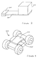
- a heat storage body 100 of the type described above is attached to one end of a good thermal conductor 200 such as a plate containing anisotropic graphite.
- Heat producing components 205 are mounted, using a thermally conductive paste such as a silver-loaded epoxy resin, on another part of the thermal conductor 200 so that heat produced by them may be transferred through the thermal conductor 200 to the heat storage body 100, in order to achieve a temperature at the heat storage body 100 sufficiently high to melt wax within it.
- the thermal conductivity of anisotropic graphite in particular, has been shown to be sufficiently high to enable it to be effective in such a role.
- the anisotropic graphite may be encapsulated in metal such as aluminium or a polymer such as polyimide and may be planar or non-planar in form, to suit the application.
- the simple configuration shown in Figure 2 may be arranged in a number of different ways according to where the heat producing components 205 are located in relation to the heat storage body 100.
- the heat storage body 100 may be mounted on a central part of a planar or non-planar thermal conductor and heat-producing components 205 may be mounted on either side of the heat storage body 100.
- a die cast aluminium box of dimensions 105mm square and 70mm tall contains sufficient wax to store heat equivalent to 35 Watt-hours while remaining within the effective upper operating temperature limit of the chosen wax.
- a heat storage body in close proximity with the equipment to be cooled.
- open cell foam particularly when made using a metal such as aluminium or copper, enables a heat storage body according to the present invention to be formed in any desired three dimensional shape to fit close to or, for example, to at least partially enclose a heat-producing component.
- a heat storage body may be entirely filled with open cell foam of a chosen thermally conductive material, or it may be only partially filled with such foam to enable the proportion of PCM, e.g. wax, to be increased.
- PCM e.g. wax
- more complex shapes may often be more easily implemented by cutting the required shape from a block of open cell foam and then cladding it as required to contain the PCM.
- a heat storage body is provided in the form of an exchangeable lid for use in cooling a piece of motorised equipment likely to be operational in high temperature conditions for relatively short periods of time.
- FIG. 3 a simplified representation of a motorised vehicle 300 is shown.
- the vehicle 300 carries within it a number of high power electrical and electronic components within an electronics bay 305 which need to be cooled during the operational activity of the vehicle.
- the vehicle 300 is also designed to operate in high temperature environments in which more conventional cooling arrangements are likely to be less effective and a supplementary cooling facility is required.
- a detachable lid 310 is provided, of the size and shape required to act as a lid to the electronics bay 305, comprising an aluminium clad section of open cell aluminium foam, shaped according to the requirements of the lid 310, that contains wax.
- Sources of heat within the electronics bay 305 may be thermally coupled to the lid 310 as required for cooling from inside the electronics bay 305.
- the lid 310 may also absorb heat from the external environment so as to reduce or delay any heating effect on the electronics bay 305 from external heat sources. Being detachable, the lid 310 may be quickly and easily replaced at intervals with a regenerated lid 310 to minimise breaks in operation of the vehicle.
- heat storage bodies of appropriate shapes and sizes, whether detachable or fixed, may be applied to assist in the cooling of components in the vehicle 300, for example of the motors and other heat-producing parts.
- Highly thermally conductive materials may be used, as described above with reference to Figure 2 , to channel heat to those heat storage bodies, including the lid 310.
- a heat storage body according to the present invention making use of an open cell structure of highly thermally conducting material to improve the transfer of heat into and out of the phase change or other latent heat material, may be made in any appropriate three dimensional shape and in any required size according to the particular thermal management and physical requirements of a piece of equipment to be cooled or protected from heat.
- Examples of an open cell structure may include open cell foams of various cell densities and regular or irregular 3-D matrix structures such as grids of various types, e.g. of rods and/or of wires, that provide a relatively large surface in contact with the LHTSM, as would be apparent to a person of ordinary skill in the relevant art.
Landscapes
- Engineering & Computer Science (AREA)
- Chemical & Material Sciences (AREA)
- Dispersion Chemistry (AREA)
- Physics & Mathematics (AREA)
- Thermal Sciences (AREA)
- Mechanical Engineering (AREA)
- General Engineering & Computer Science (AREA)
- Cooling Or The Like Of Semiconductors Or Solid State Devices (AREA)
Priority Applications (1)
| Application Number | Priority Date | Filing Date | Title |
|---|---|---|---|
| EP08275045A EP2154462A1 (fr) | 2008-08-13 | 2008-08-13 | Corps de stockage de chaleur latente |
Applications Claiming Priority (1)
| Application Number | Priority Date | Filing Date | Title |
|---|---|---|---|
| EP08275045A EP2154462A1 (fr) | 2008-08-13 | 2008-08-13 | Corps de stockage de chaleur latente |
Publications (1)
| Publication Number | Publication Date |
|---|---|
| EP2154462A1 true EP2154462A1 (fr) | 2010-02-17 |
Family
ID=40262165
Family Applications (1)
| Application Number | Title | Priority Date | Filing Date |
|---|---|---|---|
| EP08275045A Withdrawn EP2154462A1 (fr) | 2008-08-13 | 2008-08-13 | Corps de stockage de chaleur latente |
Country Status (1)
| Country | Link |
|---|---|
| EP (1) | EP2154462A1 (fr) |
Cited By (2)
| Publication number | Priority date | Publication date | Assignee | Title |
|---|---|---|---|---|
| CN102330604A (zh) * | 2010-06-17 | 2012-01-25 | 气体产品与化学公司 | 再生器、再生方法和用于再生器的液体聚合物混合物 |
| CN104697373A (zh) * | 2015-03-17 | 2015-06-10 | 东南大学 | 一种泡沫金属换热结构 |
Citations (10)
| Publication number | Priority date | Publication date | Assignee | Title |
|---|---|---|---|---|
| US3989095A (en) * | 1972-12-28 | 1976-11-02 | Ckd Praha, Oborovy Podnik | Semi conductor cooling system |
| US4341262A (en) * | 1980-05-05 | 1982-07-27 | Alspaugh Thomas R | Energy storage system and method |
| US4446916A (en) * | 1981-08-13 | 1984-05-08 | Hayes Claude Q C | Heat-absorbing heat sink |
| US4572864A (en) * | 1985-01-04 | 1986-02-25 | The United States Of America As Represented By The United States Department Of Energy | Composite materials for thermal energy storage |
| US5404272A (en) * | 1991-10-24 | 1995-04-04 | Transcal | Carrier for a card carrying electronic components and of low heat resistance |
| US5650090A (en) * | 1994-04-15 | 1997-07-22 | Phase Change Laboratories, Inc. | Compositions for thermal energy storage or thermal energy generation |
| WO2001020713A1 (fr) * | 1999-09-16 | 2001-03-22 | Raytheon Company | Procede et appareil de refroidissement equipe d'un materiau a changement de phase et de caloducs |
| US20030015811A1 (en) * | 1997-09-02 | 2003-01-23 | Klett James W. | Pitch-based carbon foam heat sink with phase change material |
| EP1333710A2 (fr) * | 2002-01-25 | 2003-08-06 | Lockheed Martin Corporation | Méthode und appareil pour absorber l' énergie thermique |
| US20080027523A1 (en) * | 2004-10-01 | 2008-01-31 | Emcools-Emergency Medical Cooling Systems Ag | Cover for Cooling a Patient and Cooling Device Comprising Such a Cover |
-
2008
- 2008-08-13 EP EP08275045A patent/EP2154462A1/fr not_active Withdrawn
Patent Citations (10)
| Publication number | Priority date | Publication date | Assignee | Title |
|---|---|---|---|---|
| US3989095A (en) * | 1972-12-28 | 1976-11-02 | Ckd Praha, Oborovy Podnik | Semi conductor cooling system |
| US4341262A (en) * | 1980-05-05 | 1982-07-27 | Alspaugh Thomas R | Energy storage system and method |
| US4446916A (en) * | 1981-08-13 | 1984-05-08 | Hayes Claude Q C | Heat-absorbing heat sink |
| US4572864A (en) * | 1985-01-04 | 1986-02-25 | The United States Of America As Represented By The United States Department Of Energy | Composite materials for thermal energy storage |
| US5404272A (en) * | 1991-10-24 | 1995-04-04 | Transcal | Carrier for a card carrying electronic components and of low heat resistance |
| US5650090A (en) * | 1994-04-15 | 1997-07-22 | Phase Change Laboratories, Inc. | Compositions for thermal energy storage or thermal energy generation |
| US20030015811A1 (en) * | 1997-09-02 | 2003-01-23 | Klett James W. | Pitch-based carbon foam heat sink with phase change material |
| WO2001020713A1 (fr) * | 1999-09-16 | 2001-03-22 | Raytheon Company | Procede et appareil de refroidissement equipe d'un materiau a changement de phase et de caloducs |
| EP1333710A2 (fr) * | 2002-01-25 | 2003-08-06 | Lockheed Martin Corporation | Méthode und appareil pour absorber l' énergie thermique |
| US20080027523A1 (en) * | 2004-10-01 | 2008-01-31 | Emcools-Emergency Medical Cooling Systems Ag | Cover for Cooling a Patient and Cooling Device Comprising Such a Cover |
Cited By (2)
| Publication number | Priority date | Publication date | Assignee | Title |
|---|---|---|---|---|
| CN102330604A (zh) * | 2010-06-17 | 2012-01-25 | 气体产品与化学公司 | 再生器、再生方法和用于再生器的液体聚合物混合物 |
| CN104697373A (zh) * | 2015-03-17 | 2015-06-10 | 东南大学 | 一种泡沫金属换热结构 |
Similar Documents
| Publication | Publication Date | Title |
|---|---|---|
| Nofal et al. | Thermal management of lithium-ion battery cells using 3D printed phase change composites | |
| Yang et al. | Numerical analysis and experimental visualization of phase change material melting process for thermal management of cylindrical power battery | |
| Yang et al. | Finned heat pipe assisted low melting point metal PCM heat sink against extremely high power thermal shock | |
| Ling et al. | Review on thermal management systems using phase change materials for electronic components, Li-ion batteries and photovoltaic modules | |
| EP0732743A2 (fr) | Dissipateurs de chaleur | |
| CA2964864C (fr) | Dispositif de capacite thermique | |
| EP2719013B1 (fr) | Système de gestion thermique de stockage d'énergie utilisant des matériaux à changement de phase à températures multiples | |
| Fang et al. | Porous-material-based composite phase change materials for a lithium-ion battery thermal management system | |
| US20070292751A1 (en) | Battery Apparatus with Heat Absorbing Body | |
| US20140369005A1 (en) | Passive thermal management device | |
| Kinkelin et al. | Theoretical and experimental study of a thermal damper based on a CNT/PCM composite structure for transient electronic cooling | |
| US11387506B2 (en) | Thermal management systems including vapor chambers and phase change materials and vehicles including the same | |
| CN114148550A (zh) | 一种用于卫星的一体化柔性储能散热装置 | |
| GB2462620A (en) | Latent heat storage body comprising a thermally conductive structure | |
| WO2009088565A2 (fr) | Procédé de création d'un puits de chaleur dans lequel est noyé du graphite thermo-pyrolytique | |
| Almajali et al. | Effect of copper coating on infiltrated PCM/foam | |
| CN105655665A (zh) | 一种动力电池的散热装置 | |
| US11243032B2 (en) | Heat sink devices and methods of using such devices for thermal management | |
| Ahmadi et al. | Lung-inspired PCM-impregnated heat sinks for transient thermal management of high-power GaN electronic chips | |
| EP2154462A1 (fr) | Corps de stockage de chaleur latente | |
| JP2015055470A (ja) | ヒートパイプ及び箔、発泡体又は他の多孔性媒体と共に相変化材料を使用したエネルギー貯蔵並びに熱管理 | |
| CN114497813B (zh) | 相变复合膜及包括所述相变复合膜的电池和芯片组件 | |
| JP7593717B2 (ja) | バスバー | |
| JP7826359B2 (ja) | 相変化材料を含むバスバ | |
| Singh et al. | Rayleigh-Bénard performance effect on battery cooling using CPCM with novel fin configuration |
Legal Events
| Date | Code | Title | Description |
|---|---|---|---|
| PUAI | Public reference made under article 153(3) epc to a published international application that has entered the european phase |
Free format text: ORIGINAL CODE: 0009012 |
|
| AK | Designated contracting states |
Kind code of ref document: A1 Designated state(s): AT BE BG CH CY CZ DE DK EE ES FI FR GB GR HR HU IE IS IT LI LT LU LV MC MT NL NO PL PT RO SE SI SK TR |
|
| AX | Request for extension of the european patent |
Extension state: AL BA MK RS |
|
| STAA | Information on the status of an ep patent application or granted ep patent |
Free format text: STATUS: THE APPLICATION HAS BEEN WITHDRAWN |
|
| 18W | Application withdrawn |
Effective date: 20100225 |