EP1334793B1 - Soudage à haute resistance de soudage par friction à mouvement cyclique - Google Patents
Soudage à haute resistance de soudage par friction à mouvement cyclique Download PDFInfo
- Publication number
- EP1334793B1 EP1334793B1 EP02025893A EP02025893A EP1334793B1 EP 1334793 B1 EP1334793 B1 EP 1334793B1 EP 02025893 A EP02025893 A EP 02025893A EP 02025893 A EP02025893 A EP 02025893A EP 1334793 B1 EP1334793 B1 EP 1334793B1
- Authority
- EP
- European Patent Office
- Prior art keywords
- friction stir
- stir welding
- welding tool
- heater
- temperature
- Prior art date
- Legal status (The legal status is an assumption and is not a legal conclusion. Google has not performed a legal analysis and makes no representation as to the accuracy of the status listed.)
- Revoked
Links
Images





Classifications
-
- B—PERFORMING OPERATIONS; TRANSPORTING
- B23—MACHINE TOOLS; METAL-WORKING NOT OTHERWISE PROVIDED FOR
- B23K—SOLDERING OR UNSOLDERING; WELDING; CLADDING OR PLATING BY SOLDERING OR WELDING; CUTTING BY APPLYING HEAT LOCALLY, e.g. FLAME CUTTING; WORKING BY LASER BEAM
- B23K20/00—Non-electric welding by applying impact or other pressure, with or without the application of heat, e.g. cladding or plating
- B23K20/24—Preliminary treatment
-
- B—PERFORMING OPERATIONS; TRANSPORTING
- B23—MACHINE TOOLS; METAL-WORKING NOT OTHERWISE PROVIDED FOR
- B23K—SOLDERING OR UNSOLDERING; WELDING; CLADDING OR PLATING BY SOLDERING OR WELDING; CUTTING BY APPLYING HEAT LOCALLY, e.g. FLAME CUTTING; WORKING BY LASER BEAM
- B23K20/00—Non-electric welding by applying impact or other pressure, with or without the application of heat, e.g. cladding or plating
- B23K20/12—Non-electric welding by applying impact or other pressure, with or without the application of heat, e.g. cladding or plating the heat being generated by friction; Friction welding
- B23K20/122—Non-electric welding by applying impact or other pressure, with or without the application of heat, e.g. cladding or plating the heat being generated by friction; Friction welding using a non-consumable tool, e.g. friction stir welding
- B23K20/123—Controlling or monitoring the welding process
- B23K20/1235—Controlling or monitoring the welding process with temperature control during joining
-
- Y—GENERAL TAGGING OF NEW TECHNOLOGICAL DEVELOPMENTS; GENERAL TAGGING OF CROSS-SECTIONAL TECHNOLOGIES SPANNING OVER SEVERAL SECTIONS OF THE IPC; TECHNICAL SUBJECTS COVERED BY FORMER USPC CROSS-REFERENCE ART COLLECTIONS [XRACs] AND DIGESTS
- Y10—TECHNICAL SUBJECTS COVERED BY FORMER USPC
- Y10T—TECHNICAL SUBJECTS COVERED BY FORMER US CLASSIFICATION
- Y10T428/00—Stock material or miscellaneous articles
- Y10T428/12—All metal or with adjacent metals
- Y10T428/12493—Composite; i.e., plural, adjacent, spatially distinct metal components [e.g., layers, joint, etc.]
Definitions
- the present invention relates to an apparatus and method of manufacturing a structural assembly by friction stir welding, according to the preambles of claims 1 and 10 wherein the method comprises the steps of: forming a friction stir weld joint in at least one structural member using a rotating friction stir welding tool to construct the structural assembly.
- Friction stir welding is utilized to join workpieces to form structural assemblies that can be used in the manufacture of military and commercial aircraft, as well as in other applications requiring high strength weld joints.
- friction stir welding involves inserting the threaded pin 10a of a rotating friction stir welding tool 10 between the opposing faces of a pair of workpieces 12, 14 while urging the workpieces together.
- Friction stir welding can also be used to repair cracks or other defects in a single workpiece.
- the rotation of the threaded pin 10a between the opposing faces of the workpieces 12, 14, or within a single workpiece creates friction that generates sufficient heat energy to plasticize the workpiece material in the weld zone 16 .
- the friction stir welding tool 10 also includes a concave shoulder adapted to consolidate the plasticized workpiece material within the weld zone 16 as the friction stir welding tool is moved along the interface 11 between workpieces or through a single workpiece.
- a friction stir weld joint 18 forms, joining the workpieces together in a unitary assembly, as the plasticized regions of the workpieces 12, 14 flow together and cool in the weld zone 16 . See U.S. Patent No. 5,460,317 to Thomas et al. for a general discussion of friction stir welding.
- the formation of the weld joint 18 is autogenous and is created by the solidification of the plasticized parent materials rather than a filler material, as is commonly used in conventional welding processes.
- the friction stir weld joint 18 comprises a nugget having a refined grain structure with grains having an equiaxed shape and grain sizes ranging in order of magnitude from approximately 2.54 (.0001) to 5.08 x 10 -4 cm (.0002 inches) (approximately 3 to 5 microns).
- the friction stir weld joint 18 resists the formation and propagation of microcracks and exhibits improved strength, ductility and toughness, as well as improved corrosion and fatigue resistance.
- the frictional heat necessary to plasticize the workpiece material during friction stir welding can degrade the material properties of the parent materials.
- the frictional heat created by the rotating friction stir welding tool 10 is conducted from the weld zone 16 through the workpieces 12, 14 into the ambient environment, creating a heat-affected region 20 around the weld zone 16 .
- the elevated temperatures associated with the friction stir welding process can degrade the material properties of the parent materials, including the strength, stiffness, and ductility of the workpieces 12, 14 .
- Material property degradation is particularly problematic when friction stir welding precipitation hardened parent materials, which have improved mechanical properties obtained through solution and precipitation heat treatments.
- the resolution heat treatment includes solution heat treating the workpieces 12, 14 at a predetermined temperature schedule and then rapidly cooling the workpieces by quenching. The solution heat treating process is then followed by a precipitation heat treatment involving either natural or artificial aging at a second predetermined temperature schedule to recover the parent material properties.
- friction stir weld joints 18 commonly have grain sizes of up to 0,64 cm of up to (0.25 inches) after the resolution heat treatment.
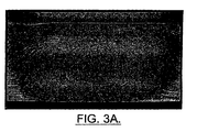
- the large grains in the friction stir weld joint 18 resulting from the resolution heat treatment adversely affect the material properties of the weld joint, including reducing the hardness, ductility, resistance to intergranular corrosion, and fatigue resistance.
- an apparatus as mentioned at the outset which additionally has at least one friction stir welding tool heater for heating said tool, said at least one heater being structured so as to be electrically insulated from the at least one structural member.
- the apparatus includes a friction stir welding tool in rotatable communication with the spindle.
- the friction stir welding tool defines a cavity.
- the apparatus includes at least one heater adapted to thermally communicate with the friction stir welding tool to thereby heat the tool and wherein the at least one heater is at least partially received in the cavity of the friction stir welding tool.
- the at least one heater can include a resistance heating coil, an induction heating coil, a quartz lamp, a gas torch, or a laser.
- the at least one heater thermally communicates with the friction stir welding tool through convection, conduction, irradiation or induction.
- the apparatus includes a sensor in thermal communication with the friction stir welding tool for measuring the temperature of the friction stir welding tool.
- the apparatus includes a controller in electrical communication with the sensor and in operable communication with the at least one heater. The controller is configured to automatically modify the heat output of the at least one heater to modify the temperature of the friction stir welding tool.
- the present invention provides an apparatus for friction stir welding at least one structural member, including a machine having a rotatable spindle.
- a friction stir welding tool is in rotatable communication with the spindle.
- the apparatus includes at least one heater adapted to thermally communicate with the friction stir welding tool to thereby heat the tool and wherein the at least one heater is structured so as to be electrically insulated from the at least one structural member.
- the at least one heater can include a resistance heating coil, an induction heating coil, a quartz lamp, a gas torch, or a laser.
- the friction stir welding tool defines a cavity adapted to at least partially receive the at least one heater.
- the at least one heater is spaced from the friction stir welding tool.
- the at least one heater thermally communicates with the friction stir welding tool through convection, conduction, irradiation or induction.
- the apparatus includes a sensor in thermal communication with the friction stir welding tool for measuring the temperature of the friction stir welding tool.
- the apparatus includes a controller in electrical communication with the sensor and in operable communication with the at least one heater. The controller is configured to automatically modify the heat output of the at least one heater to modify the temperature of the friction stir welding tool.
- the present invention also provides a method of manufacturing a structural assembly according to claim 1 including forming a friction stir weld joint in at least one structural member using a rotating friction stir welding tool.
- the method includes heating the friction stir weld tool prior to the forming step with at least one heater to thereby inhibit grain growth in the weld joint.
- the forming and heating steps are repeated to thereby join at least one additional structural member to the structural assembly.
- the at least one structural member is precipitation hardened at a predetermined temperature schedule prior to the forming step.
- the structural assembly is solution heat treated at a predetermined temperature schedule subsequent to the forming step. Thereafter, the structural assembly is precipitation heat treated by aging at a second predetermined temperature schedule.
- the heating step comprises transferring heat to the friction stir welding tool through convection, conduction, irradiation, or induction.
- the heating step comprises heating the friction stir welding tool to a temperature between about 600 °F and about 1000 F.
- the method includes measuring the temperature of the friction stir welding tool.
- the method includes automatically modifying the heat output of the at least one heater to thereby modify the temperature of the friction stir welding tool.
- the present invention provides a method and apparatus for constructing an improved precipitation hardened structural assembly having one or more friction stir weld joints with refined grain structure.
- the method and apparatus for constructing the structural assembly minimize degradation of the material properties of the friction stir weld joint during subsequent resolution heat treatments thereby effectively realizing the improved material properties associated with both friction stir welding and precipitation hardening.
- the structural assembly 22 is formed of first and second structural members 24a, 24b joined at least partially along an interface defined between the structural members by a friction stir weld joint 28 .
- the structural assembly 22 can be formed of a single structural member 24 or three or more structural members wherein the friction stir weld joint 28 is formed to repair a crack or other defect in a structural member or is formed to join the structural members, respectfully.
- the friction stir weld joint 28 can be formed to provide a region of refined grain structure within a second region of a structural member 24 having comparatively high operational stress. See copending U.S. Patent Application No. 09/589,504 filed on June 7, 2001, which is assigned to the assignee of the present invention, for a general discussion of friction stir grain refinement of structural members.
- Each structural member 24 can be machined, through known manufacturing means, from a single workpiece into a predetermined shape and thickness as required by the specific design loads and specifications of the resulting structural assembly 22 .
- a CNC milling machine can be used to machine each structural member 24 , as necessary.
- the structural members 24 can be manufactured in variety of configurations, including, for purposes of example only and not limitation, plates, blocks, tubular members and curvilinear members.
- each structural member 24 can be formed of a variety of materials, as required by the specific design loads and specifications of the resulting structural assembly 22 .
- the structural members 24 are formed of materials that can be precipitation hardened, as discussed more fully below, and preferably are formed of materials having high strength to weight ratios, including, for purposes of example only and not limitation, aluminum, aluminum alloys, titanium, and titanium alloys.
- the structural members can be formed of either similar or dissimilar metals.
- the structural members 24a, 24b are joined by friction stir welding, the structural members can be formed of dissimilar metals that would be unweldable or uneconomical to join by conventional fusion welding techniques.
- Unweldable materials when joined by conventional fusion welding techniques, produce relatively weak weld joints that tend to crack during weld solidification. Such materials include aluminum and some aluminum alloys, particularly AA series 2000 and 7000 alloys.
- the use of friction stir welding permits structural members 24a, 24b formed of unweldable materials to be securely joined.
- Friction stir welding also can be used to securely join weldable materials to other weldable and to unweldable materials.
- the method of the present invention permits the materials that form the structural members 24a, 24b to be chosen from a wider variety of light weight, high strength metals and alloys, thereby facilitating reduction of the overall weight of the resulting structural assembly 22 .
- Weight and strength are of critical concern in the aerospace industry.
- one or more of the structural members can be precipitation hardened prior to forming the structural assembly 22 and then the entire structural assembly resolution heat treated.
- the structural assembly 22 is precipitation hardened after being formed, but the individual structural members 24 are not precipitation hardened prior to forming the assembly.
- Precipitation hardening of metal alloys is a process whereby the mechanical properties of the metal alloy are improved by the formation of uniformly dispersed particles or precipitates of one or more secondary phases within the original phase matrix. Precipitation hardening requires that the metal alloy undergo two heat treatment processes, the first process being a solution heat treatment and the second process being a precipitation heat treatment.
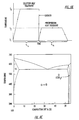
- FIG. 4A there is shown a hypothetical phase diagram for a precipitation-hardenable metal alloy composed of alloying elements A and B.
- Figure 4A illustrates a phase diagram for a binary system
- precipitation-hardenable metal alloys may contain two or more alloying elements.
- the alloy must have an appreciable maximum solubility of one element in the other, on the order of several percent, and a solubility limit that rapidly decreases in concentration of the major element with temperature reduction. Both of these requirements are satisfied by the hypothetical phase diagram of Figure 4A, where the maximum solubility is designated by M. Additionally, the composition of a precipitation-hardenable metal alloy must be less than the maximum solubility M.
- Examples of some of the binary and ternary metal alloys that are precipitation hardenable include aluminum-calcium, aluminum-chromium, aluminum-cobalt, aluminum-copper, aluminum-iron-titanium, aluminum-gallium-germanium, aluminum-gallium-indium, aluminum-germanium-tin, aluminum-lithium, aluminum-lithium-magnesium, aluminum-manganese, aluminum-molybdenum, aluminum-nickel-titanium, aluminum-niobium, aluminum-silicon, copper-beryllium, copper-tin, magnesium-aluminum, as well as some ferrous alloys.
- element A designates the original phase matrix
- element B designates the solute or secondary element.
- the phase associated with the secondary alloying element must first be completely dissolved, such that the only remaining phase is the phase associated with the original phase matrix.
- the phase associated with the secondary alloying element is dissolved through a solution heat treatment process at a first predetermined temperature schedule.
- the solution heat treatment process reference is made to Figure 4A and the metal alloy composed of a predetermined percentage of elements A and B designated by C 1 .
- the hypothetical metal alloy of the structural member will be in an equilibrium state and will contain both the ⁇ phase of element A and the ⁇ phase of element B.
- the temperature of the structural member is raised to temperature To.
- the ⁇ phase or solute atoms of element B begin to dissolve.
- the structural member is maintained at temperature To for a sufficient period of time, designated t 1 , to allow all of the ⁇ phase to dissolve so that the alloy contains only the ⁇ phase of composition C 1 .
- the structural member is rapidly cooled or quenched to ambient temperature, which is designated by T 1 , as shown in Figures 4A and 4B.
- T 1 ambient temperature
- the rapid cooling inhibits the formation of the ⁇ phase so that only the ⁇ phase solid solution supersaturated with B atoms is present.
- the structural member in the ⁇ phase at this temperature is in a nonequilibrium state with an incomplete temper, such that generally the ⁇ phase will gradually begin to form in the existing ⁇ phase matrix. In this nonequilibrium state, most metal alloys are relatively soft and weak.
- precipitation heat treating or aging requires that the structural assembly 22 undergo an isothermal heat treatment whereby the temperature of the assembly is raised to a predetermined temperature, designated by T 2 , for a predetermined amount of time, designated t 2 .
- T 2 is within the ⁇ and ⁇ two-phase region of the hypothetical phase diagram and is a temperature at which the diffusion rates for the B atoms become appreciable. The diffusion of the B atoms into a ⁇ phase results in the formation of finely dispersed particles of the B alloy element. Once the desired amount of diffusion has taken place, the structural assembly 22 may be cooled to room temperature.
- the character of the ⁇ phase particles, and thus the strength and hardness for a given metal alloy used to form the structural assembly 22 is dependent upon the precipitation temperature, designated T 2 , and the aging time at this temperature, designated t 2 .
- T 2 precipitation temperature
- t 2 aging time at this temperature
- some metal alloys will age at room temperature over an extended period of time, commonly denoted natural aging, while other metal alloys require artificially raised temperatures, commonly denoted artificial aging.
- FIG. 4C there is shown a binary system phase diagram for aluminum and copper adapted from Metals Handbook: Metallography, Structures and Phase Diagrams , Vol. 8, 8th edition, ASM Handbook Committee, T. Lyman Editor, American Society for Metals, 1973, p. 259., to further illustrate the solution heat treatment and precipitation heat treatment processes. From the diagram, the temperature range (previously designated T 0 ) to solution heat treat an aluminum-copper metal alloy having a known composition of wt% copper (previously designated C 1 ) so as to completely dissolve the copper atoms can be determined.
- the time period necessary to completely dissolve the copper atoms is dependent upon the material composition, C 1 , and the temperature, T 0 , and can be readily determined by those skilled in the art.
- the resulting alloy Upon completing the solution heat treating, the resulting alloy has an incomplete temper and is in a nonequilibrium state.
- the precipitation heat treatment process is then conducted at a temperature range of approximately 100 to 300 °C (previously designated T 2 ) for t 2 hours to complete the temper and stabilize the material properties.
- T 2 previously designated
- the structural assembly 22 includes at least one friction stir weld joint 28 that is formed prior to precipitation hardening of the assembly.
- the structural members are positioned relative to one another such that the members define an interface 32 therebetween.
- the structural members 24a, 24b preferably are secured so as to prevent movement of the members relative to one another.
- the structural members 24a, 24b can be secured to each other by spot welding or using a clamp, as is known in the art.
- the structural members 24a, 24b can then be secured to a worktable by means of a clamp or similar device (not shown).
- the structural member When forming a friction stir weld joint 28 in a single structural member 24 , the structural member preferably is secured to a worktable by means of a clamp or similar device.
- the structural members 24a, 24b are then joined to one another by friction stir welding along the interface 32 between the members, which defines the welding path 34 of the friction stir welding tool 30 .
- a rotating friction stir welding pin 30a which is attached to a friction stir welding tool 30 is forced through the outer surfaces 35 of the structural members 24a, 24b.
- the frictional heat generated by the rotating pin 30a creates a plasticized region or weld zone 36 between the structural members 24a, 24b.
- a heat-affected region 40 is created about the weld zone 16.
- a friction stir weld joint 28 can similarly be formed in a single structural member 24 to repair a crack or other defect or to form a region of refined grain structure within a second region of the structural member having comparatively high operational stress.
- a device having a rotatable spindle, such as a CNC machine, can be used to rotate and move the friction stir welding tool 30 , as is known in the art, and such devices are collectively referred to herein as "milling machines" 47 .
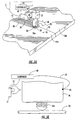
- the friction stir welding tool 30 is heated using at least one heater 41 prior to and during formation of the friction stir weld joint 28 .
- the temperature or temperature range to which the friction stir welding tool 30 is heated depends on the particular material or materials being welded. For example, for aluminum and aluminum alloys, the friction stir welding tool 30 is heated to between about 315,6°C (600°F) to about 537,8°C (1000 °F), and preferably, is heated to about 398,9°C (750 °F).
- heating the friction stir welding tool 30 prior to and during friction stir welding inhibits grain growth within the resulting friction stir weld joint 28 during subsequent precipitation hardening of the structural assembly 22 .
- friction stir welding imposes a critical amount of cold working on the structural assembly.
- the cold working results in residual strain in the weld joint that causes grain growth during subsequent solution heat treatments. It is believed that heating the friction stir welding tool prior to and during welding converts the cold working into hot working so that no residual strain occurs in the weld joint and, thus, no appreciable grain growth during subsequent solution heat treatments.
- the heater 41 is positioned externally of the friction stir welding tool 30 .
- the heater 41 can be attached to the milling machine 47 used to rotate and move the friction stir welding tool 30 so that the heater automatically moves with the tool.
- the heater 41 can be attached to a rigid or adjustable arm 48 or the like that is attached to the milling machine 47 .
- the heater 41 can be moved separately from the milling machine 47 .
- the heater is moved using a robotic arm controlled by a controller or microprocessor, such as a computer operating under software control.
- the heater 41 is moved manually by the operator.
- the heater 41 can comprises a laser that thermally communicates with, or transfers heat to, the friction stir welding tool 30 primarily by irradiation.
- the heater 41 comprises a gas torch that transfers heat to the friction stir welding tool 30 by convection and irradiation.
- the gas torch can use a liquefied hydrocarbon gas as fuel.
- the heater 41 can comprise a quartz lamp that transfers heat to the friction stir welding tool 30 by convection and irradiation.
- the heater 41 can comprise an induction heating coil positioned at least partially around the friction stir welding tool 30 that transfers heat to the friction stir welding tool by induction.
- the position of the heater 41 relative to the friction stir welding tool 30 will depend on a variety of factors, including the configuration of the structural member 24 or members 24a, 24b, and the type of heater being used.
- the heater 41 is positioned on the trailing side of the tool 30 so that heat is transferred in the direction of travel of the tool, as illustrated by the arrow 34 .
- the heater 41 can be positioned so that it transfers heat toward the tool 34 in a direction perpendicular to the direction of travel of the tool or transfers heat toward the tool in a direction opposite to the direction of tool travel.
- the heater 41 is positioned at least partially within a cavity or recess 43 defined by the friction stir welding tool 30 .
- the heater 41 can comprise one or more resistance heaters that transfer heat to the friction stir welding tool 30 by conduction and, depending on the size of the cavity, convection.
- the heater 41 can rotate with the friction stir welding tool 30 within the cavity or recess 43 or the heater can be isolated from the rotation of the friction stir welding tool 30 using bearings (not shown).
- the heaters 41 are preferably in intimate contact with friction stir welding tool 30 .
- the heater 41 can comprise a quartz lamp, gas torch or laser positioned within the cavity 43 defined by the friction stir welding tool 30 such that the heater transfers heat to the friction stir welding tool by convection and irradiation.
- the heater 41 can comprise an induction heating coil positioned within the cavity 43 defined by the friction stir welding tool 30 such that the heater transfers heat to the friction stir welding tool by induction.
- the heater 41 includes suitable wiring 51 to connect the heater to an energy source (not shown), as is known in the art.
- the heater 41 can be powered by the milling machine or by a separate energy source.
- the heater 41 preferably is electrically insulated from the structural member or members being welded.
- the heater 41 can be in electrical communication through suitable wiring 51 with a controller or microprocessor 49 , such as a computer operating under computer software control, that is configured to control the heat or energy output of the heater.
- the controller 49 can include the controller for the milling machine 47 .
- the heat output of the heater 41 can also be manually controlled.
- the wiring 51 preferably includes one or more electrical connectors (not shown) having electrically conductive rollers that continuously conduct electricity to the heater from the power source and/or controller 49 , but that allow the portion of the wiring connected to the heater to rotate while the remainder of the wiring remains fixed to thereby prevent the wiring from twisting.
- the friction stir welding tool 30 preferably includes at least one sensor 45 , such as a thermocouple, optical thermocouple, thermopile, thermometer, bimetallic temperature-sensitive element, thermoresistive element, resistance temperature detector, thermistors, a pyrometer, that is in thermal communication with the friction stir welding tool 30 for measuring the temperature of the tool prior to and during friction stir welding.
- the sensor 45 can be attached or mounted directly to the friction stir welding tool 30 using suitable fasteners or adhesive (not shown).
- an optical thermocouple can be used to monitor the temperature of the friction stir welding tool 30 from a distance.
- an optical thermocouple can be attached to the milling machine 47 using a rigid or adjustable arm or the like (not shown) so that the optical thermocouple moves with the friction stir welding tool 30 or, alternatively, the optical thermocouple 41 can be moved separately from the milling machine using a robotic arm (not shown) controlled by a controller or microprocessor, such as a computer operating under software control. In another embodiment, the optical thermocouple is moved manually by the operator.
- the sensor 45 is in electrical communication through suitable wiring 52 with the controller 49 .
- the wiring 52 preferably includes one or more electrical connectors (not shown) having electrically conductive rollers that continuously conduct the signal from the heater to the power source and/or controller 49, but that allow the portion of the wiring connected to the sensor to rotate while the remainder of the wiring remains fixed to thereby prevent the wiring from twisting.
- the senor 45 measures the temperature of the friction stir welding tool 30 continuously or at predetermined intervals and then transmits a signal representative of the temperature of the friction stir welding tool to the controller 49 .
- the controller 49 compares the temperature reading from the sensor 45 to a predetermined temperature or value.
- the controller will automatically modify the heat output of the heater 41 to thereby modify the temperature of the friction stir welding tool. More specifically, if the temperature of the friction stir welding tool 30 , as measured by the sensor 45 , is less than the predetermined temperature or value, the controller 49 will increase the heat output of the heater 41 to thereby increase the temperature of the friction stir welding tool. If the temperature of the friction stir welding tool 30 , as measured by the sensor 45 , is greater than the predetermined temperature or value, the controller 49 will decrease the heat output of the heater 41 to thereby decrease the temperature of the friction stir welding tool.
- the resulting structural assembly 22 can be resolution heat treated, as described above.
- the friction stir weld joint or joints 28 will not exhibit appreciable grain growth during or after the resolution heat treatment.
- the friction stir weld joint 28 has a refined grain structure having grain size of less than about 5 microns.
- the structural assembly 22 may be installed by attaching the assembly to other structural assemblies, so as to form the frame of an aircraft.
- the method includes mounting a friction stir welding tool to a rotatable spindle such that the friction stir welding tool rotates with the spindle. See block 61 .
- the friction stir welding tool is heated with a heater to thereby inhibit grain growth in the weld joint. See block 62 .
- the heating step includes transferring heat to the friction stir welding tool through convection, conduction, irradiation, or induction. See block 63 .
- the heating step includes heating the friction stir welding tool to a temperature between about 315,6°C (600 °F) and about 537,8°C (1000 °F). See block 64 .
- the friction stir welding tool is inserted into at least one structural member. See block 65 .
- the friction stir welding tool is heated concurrently with the inserting step. See block 66 .
- the at least one structural member can be precipitation hardened prior to the inserting step. See block 60 .
- the friction stir welding tool is moved through the at least one structural member to form the friction stir weld joint. See block 67 .
- the temperature of the friction stir welding tool is measured. See block 68 .
- the heat output of the at least one heater is then automatically modified to thereby modify the temperature of the friction stir welding tool. See block 69 .
- the at least one structural member and friction stir weld joint are solution heat treated at a predetermined temperature schedule subsequent to the moving step. See block 70 . Thereafter, the at least one structural member and friction stir weld joint are precipitation heat treated by aging at a second predetermined temperature schedule. See block 71 .
- the method includes heating a friction stir weld tool with a heater to thereby inhibit grain growth in the weld joint. See block 81 .
- the heating step includes transferring heat to the friction stir welding tool through convection, conduction, irradiation, or induction. See block 82 .
- the heating step includes heating the friction stir welding tool to a temperature between about 315,6°C (600 °F) and about 537,8°C (1000 °F) See block 83 .
- a friction stir weld joint is then formed in at least one structural member using the rotating friction stir welding tool. See block 84 .
- the at least one structural member can be precipitation hardened at a predetermined temperature schedule prior to the forming step. See block 80 .
- the friction stir weld tool is heated during the forming step with a heater to thereby inhibit grain growth in the weld joint. See block 85 .
- the temperature of the friction stir welding tool is measured. See block 86 .
- the heat output of the at least one heater can then be automatically modified to thereby modify the temperature of the friction stir welding tool. See block 87 .
- the forming and heating steps are repeated to thereby join at least one additional structural member to the structural assembly. See block 88 .
- the structural assembly is solution heat treated at a predetermined temperature schedule subsequent to the forming step. See block 89 . Thereafter, the structural assembly is precipitation heat treated by aging at a second predetermined temperature schedule. See block 90 .
Landscapes
- Engineering & Computer Science (AREA)
- Mechanical Engineering (AREA)
- Pressure Welding/Diffusion-Bonding (AREA)
Claims (16)
- Procédé de fabrication d'un ensemble structurel (22) formé de matériaux pouvant être durcis par précipitation, comprenant les étapes consistant à :former (84) un joint soudé par friction malaxage (28) dans au moins un élément structurel (24a, b) à l'aide d'un outil de soudage par friction malaxage (30) pour construire l'ensemble structurel (22) ; caractérisé parle chauffage (83, 85) de l'outil de soudage par friction malaxage (30) avant ladite étape de formation (84) avec au moins un élément chauffant (41) pour ainsi inhiber la croissance de grain dans le joint soudé (28), et le traitement thermique de résolution ou le durcissement par précipitation de l'ensemble structurel (22).
- Procédé selon la revendication 1, caractérisé par la répétition (88) desdites étapes de formation et de chauffage (83-85) pour ainsi assembler au moins un élément structurel supplémentaire (24a, b) à l'ensemble structurel (22).
- Procédé selon la revendication 1 ou 2, caractérisé par le durcissement par précipitation (80) d'au moins un élément structurel (24a, b) selon un programme de température prédéterminé avant ladite étape de formation (84).
- Procédé selon l'une quelconque des revendications 1 à 3, caractérisé en ce que le traitement thermique de mise en solution (89) de l'ensemble structurel (22) est réalisé selon un programme de température prédéterminé suite à ladite étape de formation (84).
- Procédé selon la revendication 4, caractérisé en ce que l'ensemble structurel (22) est vieilli selon un second programme de température prédéterminé.
- Procédé selon l'une quelconque des revendications 1 à 5, caractérisé en ce que ladite étape de chauffage (62, 64 ; 83, 85) comprend l'étape consistant à transférer de la chaleur à l'outil de soudage par friction malaxage (30) par un type de transfert de chaleur sélectionné dans le groupe comprenant la convection, la conduction, l'irradiation et l'induction.
- Procédé selon l'une quelconque des revendications 1 à 6, caractérisé en ce que ladite étape de chauffage (62, 64 ; 83, 85) comprend le chauffage (64 ; 83) de l'outil de soudage par friction malaxage (30) jusqu'à une température comprise entre environ 315,6 °C et environ 537,8 °C.
- Procédé selon l'une quelconque des revendications 1 à 7, caractérisé en ce qu'il comprend en outre l'étape consistant à mesurer (68 ; 86) la température de l'outil de soudage par friction malaxage (30).
- Procédé selon la revendication 8, caractérisé en ce qu'il comprend en outre l'étape consistant à modifier automatiquement (69 ; 87) la production de chaleur d'au moins un élément chauffant (41) pour ainsi modifier la température de l'outil de soudage par friction malaxage (30).
- Appareil pour le soudage par friction malaxage d'au moins un élément structurel (24a, b), comprenant :une machine (47) ayant une tige rotative ; etun outil de soudage par friction malaxage (30) en communication rotative avec ladite tige ;caractérisé par
au moins un élément chauffant (41) de l'outil de soudage par friction malaxage pour chauffer ledit outil (30), ledit au moins un élément chauffant (41) étant structuré de manière à être isolé électriquement d'au moins un élément structurel (24a, b). - Appareil selon la revendication 10, caractérisé en ce que ledit outil de soudage par friction malaxage (30) définit une cavité (43) adaptée pour recevoir au moins partiellement au moins un élément chauffant (41).
- Appareil selon la revendication 10 ou 11, caractérisé en ce qu'au moins un élément chauffant (41) est sélectionné dans le groupe constitué d'une bobine de chauffage par résistance, d'une bobine de chauffage par induction, d'une lampe à quartz, d'un chalumeau à gaz et d'un laser.
- Appareil selon l'une quelconque des revendications 10 à 12, caractérisé en ce qu'au moins un élément chauffant (41) communique thermiquement avec ledit outil de soudage par friction malaxage par l'intermédiaire d'un type de transfert de chaleur sélectionné dans le groupe constitué de la convection, la conduction, l'irradiation et l'induction.
- Appareil selon la revendication 10, caractérisé en ce qu'au moins un élément chauffant (41) est espacé dudit outil de soudage par friction malaxage (30).
- Appareil selon l'une quelconque des revendications 10 à 14, caractérisé par un capteur (45) en communication thermique avec ledit outil de soudage par friction malaxage (30) pour mesurer la température dudit outil de soudage par friction malaxage (30).
- Appareil selon la revendication 15, caractérisé par un dispositif de régulation (49) en communication électrique avec ledit capteur (45) et en communication opérationnelle avec le au moins un élément chauffant (41), ledit dispositif de régulation (49) étant configuré pour modifier automatiquement la production de chaleur dudit au moins un élément chauffant (41) afin de modifier la température dudit outil de soudage par friction malaxage (30).
Priority Applications (1)
| Application Number | Priority Date | Filing Date | Title |
|---|---|---|---|
| EP07005582A EP1813377B1 (fr) | 2001-12-26 | 2002-11-20 | Appareil de soudage par friction malaxage |
Applications Claiming Priority (2)
| Application Number | Priority Date | Filing Date | Title |
|---|---|---|---|
| US10/035,865 US6780525B2 (en) | 2001-12-26 | 2001-12-26 | High strength friction stir welding |
| US35865 | 2001-12-26 |
Related Child Applications (1)
| Application Number | Title | Priority Date | Filing Date |
|---|---|---|---|
| EP07005582A Division EP1813377B1 (fr) | 2001-12-26 | 2002-11-20 | Appareil de soudage par friction malaxage |
Publications (2)
| Publication Number | Publication Date |
|---|---|
| EP1334793A1 EP1334793A1 (fr) | 2003-08-13 |
| EP1334793B1 true EP1334793B1 (fr) | 2007-03-21 |
Family
ID=21885248
Family Applications (2)
| Application Number | Title | Priority Date | Filing Date |
|---|---|---|---|
| EP02025893A Revoked EP1334793B1 (fr) | 2001-12-26 | 2002-11-20 | Soudage à haute resistance de soudage par friction à mouvement cyclique |
| EP07005582A Expired - Lifetime EP1813377B1 (fr) | 2001-12-26 | 2002-11-20 | Appareil de soudage par friction malaxage |
Family Applications After (1)
| Application Number | Title | Priority Date | Filing Date |
|---|---|---|---|
| EP07005582A Expired - Lifetime EP1813377B1 (fr) | 2001-12-26 | 2002-11-20 | Appareil de soudage par friction malaxage |
Country Status (6)
| Country | Link |
|---|---|
| US (1) | US6780525B2 (fr) |
| EP (2) | EP1334793B1 (fr) |
| JP (1) | JP2003236681A (fr) |
| CA (3) | CA2863628C (fr) |
| DE (1) | DE60218976T2 (fr) |
| ES (1) | ES2282360T3 (fr) |
Families Citing this family (64)
| Publication number | Priority date | Publication date | Assignee | Title |
|---|---|---|---|---|
| DE69712078T2 (de) * | 1997-12-19 | 2002-12-12 | Esab Ab, Goeteborg/Gothenburg | Schweissvorrichtung |
| CN1191144C (zh) | 2000-05-08 | 2005-03-02 | 布莱阿姆青年大学 | 摩擦搅拌焊接的超级研磨工具和方法 |
| DE10036170C1 (de) * | 2000-07-25 | 2001-12-06 | Eads Deutschland Gmbh | Laserunterstütztes Reibrührschweißverfahren |
| EP2080579A1 (fr) * | 2001-03-07 | 2009-07-22 | Showa Denko K.K. | Procédé de jointure par friction-malaxage, procédé de fabrication d'éléments aboutés joints et appareil de jointure par friction-malaxage |
| DE60206893T2 (de) * | 2001-03-29 | 2006-07-27 | Mazda Motor Corp. | Drehendes reibungschweissverfahren und vorrichtung |
| DE10139687C1 (de) * | 2001-08-11 | 2003-02-20 | Eads Deutschland Gmbh | Reibrührwerkzeug zum Reibschweißen |
| US6780525B2 (en) * | 2001-12-26 | 2004-08-24 | The Boeing Company | High strength friction stir welding |
| US6908690B2 (en) * | 2002-04-29 | 2005-06-21 | The Boeing Company | Method and apparatus for friction stir welding |
| US6742697B2 (en) * | 2002-04-29 | 2004-06-01 | The Boeing Company | Joining of structural members by friction plug welding |
| US6726085B2 (en) * | 2002-05-14 | 2004-04-27 | The Boeing Company | Method and apparatus for producing a refined grain structure |
| US6776328B2 (en) * | 2002-09-17 | 2004-08-17 | The Boeing Company | Radiation assisted friction welding |
| JP2004195525A (ja) * | 2002-12-20 | 2004-07-15 | Hitachi Ltd | 摩擦攪拌接合方法 |
| US6802444B1 (en) * | 2003-03-17 | 2004-10-12 | The United States Of America As Represented By The National Aeronautics And Space Administration | Heat treatment of friction stir welded 7X50 aluminum |
| FR2855083B1 (fr) * | 2003-05-20 | 2006-05-26 | Pechiney Rhenalu | Procede de fabrication de pieces en alliage d'aluminium soudees par friction |
| US7216793B2 (en) * | 2003-08-22 | 2007-05-15 | Edison Welding Institute, Inc. | Friction stir welding travel axis load control method and apparatus |
| US7121448B2 (en) * | 2003-08-29 | 2006-10-17 | General Electric Company | Friction stir welding apparatus and associated thermal management systems and methods |
| US20050167401A1 (en) * | 2004-02-02 | 2005-08-04 | Stresswave, Inc. | Treatment of spot welded joints for fatigue life improvement |
| US20050246884A1 (en) * | 2004-02-27 | 2005-11-10 | Chan-Tung Chen | Friction welding structure for striking plate of golf club head and method therefor |
| US20050210820A1 (en) * | 2004-03-24 | 2005-09-29 | Shinmaywa Industries, Ltd. | Frame and method for fabricating the same |
| US10316616B2 (en) * | 2004-05-28 | 2019-06-11 | Schlumberger Technology Corporation | Dissolvable bridge plug |
| US8211247B2 (en) * | 2006-02-09 | 2012-07-03 | Schlumberger Technology Corporation | Degradable compositions, apparatus comprising same, and method of use |
| KR100571522B1 (ko) * | 2004-06-24 | 2006-04-17 | 한국기계연구원 | 표면이동마찰용접법에 의한 미세립 금속판재의 고상접합방법 |
| US7614539B2 (en) * | 2004-09-13 | 2009-11-10 | The Boeing Company | Method to improve properties of aluminum alloys processed by solid state joining |
| ATE431770T1 (de) * | 2004-09-14 | 2009-06-15 | Alcan Rhenalu | Geschweisstes strukturelement mit mindestens zwei aluminiumlegierungsteilen, die verschiedene metallurgische zustände haben, und verfahren zur herstellung solch eines elements |
| JP4468125B2 (ja) * | 2004-09-27 | 2010-05-26 | 三菱重工業株式会社 | 摩擦撹拌接合方法及び装置 |
| US7225969B2 (en) * | 2004-12-10 | 2007-06-05 | Gm Global Technology Operations, Inc. | Friction stir processing for surface properties |
| US20060177284A1 (en) * | 2005-02-07 | 2006-08-10 | The Boeing Company | Method for preparing pre-coated aluminum and aluminum-alloy fasteners and components having high-shear strength and readily deformable regions |
| US20060283918A1 (en) * | 2005-02-11 | 2006-12-21 | London Blair D | Use of friction stir processing and friction stir welding for nitinol medical devices |
| US8567494B2 (en) | 2005-08-31 | 2013-10-29 | Schlumberger Technology Corporation | Well operating elements comprising a soluble component and methods of use |
| US8083871B2 (en) | 2005-10-28 | 2011-12-27 | Automotive Casting Technology, Inc. | High crashworthiness Al-Si-Mg alloy and methods for producing automotive casting |
| US8231947B2 (en) * | 2005-11-16 | 2012-07-31 | Schlumberger Technology Corporation | Oilfield elements having controlled solubility and methods of use |
| US8220554B2 (en) * | 2006-02-09 | 2012-07-17 | Schlumberger Technology Corporation | Degradable whipstock apparatus and method of use |
| US8770261B2 (en) | 2006-02-09 | 2014-07-08 | Schlumberger Technology Corporation | Methods of manufacturing degradable alloys and products made from degradable alloys |
| US8211248B2 (en) * | 2009-02-16 | 2012-07-03 | Schlumberger Technology Corporation | Aged-hardenable aluminum alloy with environmental degradability, methods of use and making |
| US8695868B2 (en) * | 2006-08-30 | 2014-04-15 | Fluor Technologies Corporation | Compositions and methods for dissimilar material welding |
| US20080277036A1 (en) * | 2007-05-11 | 2008-11-13 | Luxfer Group Limited | Method for manufacturing tanks |
| US8673209B2 (en) * | 2007-05-14 | 2014-03-18 | Alcoa Inc. | Aluminum alloy products having improved property combinations and method for artificially aging same |
| US8840737B2 (en) * | 2007-05-14 | 2014-09-23 | Alcoa Inc. | Aluminum alloy products having improved property combinations and method for artificially aging same |
| US20080311421A1 (en) * | 2007-06-15 | 2008-12-18 | United Technologies Corporation | Friction stir welded structures derived from AL-RE-TM alloys |
| US20090007774A1 (en) * | 2007-07-02 | 2009-01-08 | Terence Savas | Aircraft actuator piston |
| KR100986934B1 (ko) * | 2007-07-13 | 2010-10-08 | 현대자동차주식회사 | 연료전지의 금속분리판 용접장치 |
| US20090255980A1 (en) * | 2008-04-15 | 2009-10-15 | Lockheed Martin Corporation | Control systems for friction stir welding of titanium alloys and other high temperature materials |
| WO2010019232A1 (fr) * | 2008-08-11 | 2010-02-18 | Sii Megadiamond, Inc. | Procédé pour utiliser des paramètres de commande d'outil modifiables pour commander la température de l'outil durant un soudage par friction-malaxage |
| US8206517B1 (en) | 2009-01-20 | 2012-06-26 | Alcoa Inc. | Aluminum alloys having improved ballistics and armor protection performance |
| FR2945464B1 (fr) | 2009-05-13 | 2012-03-23 | Alcan Rhenalu | Procede d'assemblage par soudage de pieces en alliage d'aluminium. |
| JP5391046B2 (ja) * | 2009-12-07 | 2014-01-15 | 川崎重工業株式会社 | 摩擦攪拌接合装置及びその接合方法 |
| US8141764B1 (en) | 2010-04-06 | 2012-03-27 | United Launch Alliance, Llc | Friction stir welding apparatus, system and method |
| US7866532B1 (en) | 2010-04-06 | 2011-01-11 | United Launch Alliance, Llc | Friction stir welding apparatus, system and method |
| US8123104B1 (en) | 2010-04-06 | 2012-02-28 | United Launch Alliance, Llc | Friction welding apparatus, system and method |
| JP2012107593A (ja) * | 2010-11-19 | 2012-06-07 | Hitachi Ltd | 蒸気タービンバルブ |
| US10647064B2 (en) * | 2011-12-01 | 2020-05-12 | Lawrence Livermore National Security, Llc | System and method for light assisted friction stir processing and welding of metallic and non-metallic materials |
| US8672211B2 (en) * | 2012-05-18 | 2014-03-18 | GM Global Technology Operations LLC | Vibration welding system with thin film sensor |
| JP5942034B2 (ja) * | 2013-02-26 | 2016-06-29 | 株式会社日立製作所 | 摩擦撹拌接合装置および接合方法 |
| WO2015045299A1 (fr) * | 2013-09-30 | 2015-04-02 | Jfeスチール株式会社 | Procédé de soudage par friction-malaxage pour acier de structure et procédé de fabrication de raccord lié pour acier de structure |
| WO2015045421A1 (fr) * | 2013-09-30 | 2015-04-02 | Jfeスチール株式会社 | Procédé d'assemblage par friction/brassage de tôles et procédé de production d'un joint lié |
| WO2015045420A1 (fr) * | 2013-09-30 | 2015-04-02 | Jfeスチール株式会社 | Procédé d'assemblage par friction/brassage de tôles et procédé de production d'un joint lié |
| JP2016124002A (ja) * | 2014-12-26 | 2016-07-11 | トヨタ自動車株式会社 | 摩擦点接合装置および摩擦点接合方法 |
| JP6143915B1 (ja) * | 2016-04-28 | 2017-06-07 | 株式会社日立パワーソリューションズ | 摩擦攪拌接合装置 |
| JP6766446B2 (ja) * | 2016-05-25 | 2020-10-14 | 株式会社Ihi | 摩擦撹拌接合装置 |
| US11135674B2 (en) * | 2016-06-27 | 2021-10-05 | Kawasaki Jukogyo Kabushiki Kaisha | Friction stir spot welding method and friction stir spot welding device |
| JP6875698B2 (ja) * | 2017-02-27 | 2021-05-26 | 国立大学法人大阪大学 | 摩擦攪拌接合装置及び摩擦攪拌接合方法 |
| JP6624127B2 (ja) * | 2017-03-13 | 2019-12-25 | Jfeスチール株式会社 | 表面改質装置および表面改質方法、ならびに金属材の製造方法 |
| FR3083630B1 (fr) * | 2018-07-03 | 2020-11-27 | Constellium Issoire | Procede de fabrication d'une piece bi-metallique, mettant en œuvre un traitement thermique induisant une dilatation |
| WO2022010718A1 (fr) * | 2020-07-09 | 2022-01-13 | Lam Research Corporation | Traitement par friction-malaxage pour la résistance à la corrosion |
Family Cites Families (34)
| Publication number | Priority date | Publication date | Assignee | Title |
|---|---|---|---|---|
| GB9125978D0 (en) * | 1991-12-06 | 1992-02-05 | Welding Inst | Hot shear butt welding |
| US7235212B2 (en) * | 2001-02-09 | 2007-06-26 | Ques Tek Innovations, Llc | Nanocarbide precipitation strengthened ultrahigh strength, corrosion resistant, structural steels and method of making said steels |
| US6516992B1 (en) * | 1996-05-31 | 2003-02-11 | The Boeing Company | Friction stir welding with simultaneous cooling |
| JP3081799B2 (ja) * | 1996-11-01 | 2000-08-28 | 昭和アルミニウム株式会社 | アルミニウム材の接合方法 |
| US5829664A (en) * | 1996-11-15 | 1998-11-03 | Aluminum Company Of America | Resistance heated stir welding |
| JP3081808B2 (ja) * | 1997-02-17 | 2000-08-28 | 昭和アルミニウム株式会社 | 摩擦撹拌接合法 |
| US6264088B1 (en) * | 1997-05-16 | 2001-07-24 | Esab Ab | Welding assembly for friction stir welding |
| JPH10328855A (ja) * | 1997-05-30 | 1998-12-15 | Showa Alum Corp | 異種金属が接合された導電性接合体の製造方法 |
| JP3394156B2 (ja) * | 1997-06-12 | 2003-04-07 | 株式会社日立製作所 | 溶接構造物とその製造法 |
| JP3891642B2 (ja) * | 1997-06-26 | 2007-03-14 | 昭和電工株式会社 | 摩擦撹拌接合方法 |
| JP3081817B2 (ja) * | 1997-08-19 | 2000-08-28 | 昭和アルミニウム株式会社 | 異種金属製ワーク同士の摩擦撹拌接合方法 |
| NO980542D0 (no) * | 1998-02-09 | 1998-02-09 | Norsk Hydro As | Modifisert omröringsfriksjonssveising |
| US6168067B1 (en) | 1998-06-23 | 2001-01-02 | Mcdonnell Douglas Corporation | High strength friction stir welding |
| JP4286962B2 (ja) * | 1999-04-21 | 2009-07-01 | 昭和電工株式会社 | 摩擦攪拌接合方法 |
| US6168066B1 (en) * | 1999-04-21 | 2001-01-02 | Lockheed Martin Corp. | Friction stir conduction controller |
| JP2001047260A (ja) * | 1999-08-06 | 2001-02-20 | Mitsubishi Heavy Ind Ltd | 長手方向に断面形状が変化している部材の製造方法、その製造方法により製造された部材およびその部材を用いた航空機 |
| US6457629B1 (en) * | 1999-10-04 | 2002-10-01 | Solidica, Inc. | Object consolidation employing friction joining |
| EP1160029B1 (fr) | 1999-12-27 | 2005-03-02 | Mazda Motor Corporation | Procede de traitement de surface et tete de cylindre ainsi traitee |
| US6302315B1 (en) * | 2000-05-01 | 2001-10-16 | General Tool Company | Friction stir welding machine and method |
| US6398883B1 (en) * | 2000-06-07 | 2002-06-04 | The Boeing Company | Friction stir grain refinement of structural members |
| DE10035332C1 (de) * | 2000-07-20 | 2002-02-28 | Eads Deutschland Gmbh | Verfahren und Vorrichtung zum Reibrührschweißen |
| IL156386A0 (en) * | 2000-12-21 | 2004-01-04 | Alcoa Inc | Aluminum alloy products and artificial aging method |
| US6712916B2 (en) * | 2000-12-22 | 2004-03-30 | The Curators Of The University Of Missouri | Metal superplasticity enhancement and forming process |
| JP2002273579A (ja) * | 2001-03-15 | 2002-09-25 | Hitachi Ltd | 鉄基材料の接合方法およびその構造物 |
| IL142101A0 (en) | 2001-03-19 | 2002-03-10 | Rotem Ind Ltd | Improved process and apparatus for friction stir welding |
| JP4294231B2 (ja) * | 2001-04-20 | 2009-07-08 | 昭和電工株式会社 | 摩擦撹拌接合法及び摩擦撹拌接合用工具の加熱装置 |
| DE10139687C1 (de) | 2001-08-11 | 2003-02-20 | Eads Deutschland Gmbh | Reibrührwerkzeug zum Reibschweißen |
| US6660106B1 (en) * | 2001-08-22 | 2003-12-09 | The Boeing Company | Methods of manufacture of spin-forming blanks, particularly for fabrication of rocket domes |
| US6543671B2 (en) * | 2001-09-05 | 2003-04-08 | Lockheed Martin Corporation | Apparatus and method for friction stir welding using filler material |
| JP4235873B2 (ja) * | 2001-09-10 | 2009-03-11 | 株式会社安川電機 | 摩擦撹拌接合法の加熱装置 |
| JP4235874B2 (ja) * | 2001-09-20 | 2009-03-11 | 株式会社安川電機 | 摩擦撹拌接合法の加熱装置 |
| SE522075C2 (sv) | 2001-10-23 | 2004-01-13 | Svensk Kaernbraenslehantering | Förfarande för friktionsomröringssvetsning |
| CN100406190C (zh) * | 2001-11-02 | 2008-07-30 | 波音公司 | 形成具有残余压应力分布形式的焊接接头的装置和方法 |
| US6780525B2 (en) * | 2001-12-26 | 2004-08-24 | The Boeing Company | High strength friction stir welding |
-
2001
- 2001-12-26 US US10/035,865 patent/US6780525B2/en not_active Expired - Lifetime
-
2002
- 2002-11-05 CA CA2863628A patent/CA2863628C/fr not_active Expired - Lifetime
- 2002-11-05 CA CA2685022A patent/CA2685022C/fr not_active Expired - Lifetime
- 2002-11-05 CA CA2411133A patent/CA2411133C/fr not_active Expired - Lifetime
- 2002-11-20 ES ES02025893T patent/ES2282360T3/es not_active Expired - Lifetime
- 2002-11-20 EP EP02025893A patent/EP1334793B1/fr not_active Revoked
- 2002-11-20 EP EP07005582A patent/EP1813377B1/fr not_active Expired - Lifetime
- 2002-11-20 DE DE60218976T patent/DE60218976T2/de not_active Expired - Lifetime
- 2002-12-25 JP JP2002374787A patent/JP2003236681A/ja active Pending
Also Published As
| Publication number | Publication date |
|---|---|
| EP1813377A2 (fr) | 2007-08-01 |
| ES2282360T3 (es) | 2007-10-16 |
| CA2411133A1 (fr) | 2003-06-26 |
| DE60218976D1 (de) | 2007-05-03 |
| CA2863628C (fr) | 2018-07-24 |
| CA2685022A1 (fr) | 2003-06-26 |
| US6780525B2 (en) | 2004-08-24 |
| CA2863628A1 (fr) | 2003-06-26 |
| EP1813377B1 (fr) | 2012-01-04 |
| EP1334793A1 (fr) | 2003-08-13 |
| JP2003236681A (ja) | 2003-08-26 |
| CA2685022C (fr) | 2015-01-06 |
| US20030116608A1 (en) | 2003-06-26 |
| DE60218976T2 (de) | 2007-12-20 |
| CA2411133C (fr) | 2010-06-08 |
| EP1813377A3 (fr) | 2009-08-26 |
Similar Documents
| Publication | Publication Date | Title |
|---|---|---|
| EP1334793B1 (fr) | Soudage à haute resistance de soudage par friction à mouvement cyclique | |
| EP1439933B1 (fr) | Appareil et procede de formation de joints soudes presentant des motifs de contrainte residuelle de compression | |
| Zhang et al. | A comparative study on the microstructure and properties of copper joint between MIG welding and laser-MIG hybrid welding | |
| US6726085B2 (en) | Method and apparatus for producing a refined grain structure | |
| Marzbanrad et al. | Characterization of the influence of tool pin profile on microstructural and mechanical properties of friction stir welding | |
| US6168067B1 (en) | High strength friction stir welding | |
| US3823299A (en) | Metallurgical bonding and forming processes and apparatus | |
| Upadhyay et al. | Thermal management in friction-stir welding of precipitation-hardened aluminum alloys | |
| JP4328622B2 (ja) | 軽金属部品を接合する方法および装置 | |
| Yilbas et al. | Investigation into the properties of friction-welded aluminium bars | |
| Verma et al. | Study of temperature distribution and parametric optimization during fsw of AA6082 using statistical approaches | |
| Colligan | Friction Stir Welding of Aluminum Alloys | |
| Risonarta et al. | Artificial aging heat treatment post-effect on profile and mechanical properties of the AA 6061 friction welding joint | |
| Xue et al. | Electromagnetic induction heating pulsation aging for large friction stir welded 2219 aluminum structures: experiments and simulation | |
| Mohammadtaheri et al. | The effects of heat treatment and cold working on the microstructure of aluminum alloys welded by friction stir welding (FSW) technique | |
| Chaturvedi et al. | Friction Stir Welding and Design | |
| Farooq et al. | Optimization of process parameters of friction stir welded joint of dissimilar aluminum alloy AA5083 and AA6082 | |
| Gangadhariah | Design and Optimization of Friction Stir Welding | |
| Ma’arif et al. | Characteristic of friction welding weld joint of AA6061 on elevated environmental temperature | |
| Mohammed et al. | Metallographic Studies of Friction Welded High Strength Aluminium Alloy (AA7075) | |
| Aloyaydi | The Control of Friction Stir Welding Plunge Force and Power and Energy Consumption Through the Variation of Process Parameters | |
| Kundu | Abnormal grain growth of AA2195 friction stir weld nugget during solution heat treatment | |
| Abbass et al. | INTERNATIONAL JOURNAL OF ENGINEERING SCIENCES & RESEARCH TECHNOLOGY OPTIMIZATION OF FRICTION STIR SPOT WELDING PARAMETERS OF DISSIMILAR WELDED JOINTS OF ALUMINUM ALLOY (AA2024T3) WITH PURE COPPER SHEETS | |
| Zettler | The Development of Process Technology for the Friction Stir Welding of Thick Section Aluminium Alloys |
Legal Events
| Date | Code | Title | Description |
|---|---|---|---|
| PUAI | Public reference made under article 153(3) epc to a published international application that has entered the european phase |
Free format text: ORIGINAL CODE: 0009012 |
|
| AK | Designated contracting states |
Designated state(s): AT BE BG CH CY CZ DE DK EE ES FI FR GB GR IE IT LI LU MC NL PT SE SK TR |
|
| AX | Request for extension of the european patent |
Extension state: AL LT LV MK RO SI |
|
| 17P | Request for examination filed |
Effective date: 20040204 |
|
| AKX | Designation fees paid |
Designated state(s): DE ES FR GB IT |
|
| 17Q | First examination report despatched |
Effective date: 20040419 |
|
| GRAP | Despatch of communication of intention to grant a patent |
Free format text: ORIGINAL CODE: EPIDOSNIGR1 |
|
| GRAS | Grant fee paid |
Free format text: ORIGINAL CODE: EPIDOSNIGR3 |
|
| GRAA | (expected) grant |
Free format text: ORIGINAL CODE: 0009210 |
|
| AK | Designated contracting states |
Kind code of ref document: B1 Designated state(s): DE ES FR GB IT |
|
| REG | Reference to a national code |
Ref country code: GB Ref legal event code: FG4D |
|
| REF | Corresponds to: |
Ref document number: 60218976 Country of ref document: DE Date of ref document: 20070503 Kind code of ref document: P |
|
| ET | Fr: translation filed | ||
| REG | Reference to a national code |
Ref country code: ES Ref legal event code: FG2A Ref document number: 2282360 Country of ref document: ES Kind code of ref document: T3 |
|
| PLBI | Opposition filed |
Free format text: ORIGINAL CODE: 0009260 |
|
| PLAX | Notice of opposition and request to file observation + time limit sent |
Free format text: ORIGINAL CODE: EPIDOSNOBS2 |
|
| 26 | Opposition filed |
Opponent name: AIRBUS SAS/AIRBUS FRANCE/AIRBUS UK LIMITED AIRBUS Effective date: 20071221 |
|
| PLBB | Reply of patent proprietor to notice(s) of opposition received |
Free format text: ORIGINAL CODE: EPIDOSNOBS3 |
|
| PLAB | Opposition data, opponent's data or that of the opponent's representative modified |
Free format text: ORIGINAL CODE: 0009299OPPO |
|
| RDAF | Communication despatched that patent is revoked |
Free format text: ORIGINAL CODE: EPIDOSNREV1 |
|
| R26 | Opposition filed (corrected) |
Opponent name: AIRBUS SAS(FR)/ AIRBUS OPERATIONS SAS(FR)/ AIRBUS Effective date: 20071221 |
|
| APBM | Appeal reference recorded |
Free format text: ORIGINAL CODE: EPIDOSNREFNO |
|
| APBP | Date of receipt of notice of appeal recorded |
Free format text: ORIGINAL CODE: EPIDOSNNOA2O |
|
| APAH | Appeal reference modified |
Free format text: ORIGINAL CODE: EPIDOSCREFNO |
|
| APBQ | Date of receipt of statement of grounds of appeal recorded |
Free format text: ORIGINAL CODE: EPIDOSNNOA3O |
|
| PGFP | Annual fee paid to national office [announced via postgrant information from national office to epo] |
Ref country code: FR Payment date: 20121206 Year of fee payment: 11 Ref country code: DE Payment date: 20121128 Year of fee payment: 11 |
|
| REG | Reference to a national code |
Ref country code: DE Ref legal event code: R064 Ref document number: 60218976 Country of ref document: DE Ref country code: DE Ref legal event code: R103 Ref document number: 60218976 Country of ref document: DE |
|
| PGFP | Annual fee paid to national office [announced via postgrant information from national office to epo] |
Ref country code: ES Payment date: 20121126 Year of fee payment: 11 Ref country code: GB Payment date: 20121126 Year of fee payment: 11 |
|
| APBU | Appeal procedure closed |
Free format text: ORIGINAL CODE: EPIDOSNNOA9O |
|
| RDAG | Patent revoked |
Free format text: ORIGINAL CODE: 0009271 |
|
| STAA | Information on the status of an ep patent application or granted ep patent |
Free format text: STATUS: PATENT REVOKED |
|
| 27W | Patent revoked |
Effective date: 20130218 |
|
| GBPR | Gb: patent revoked under art. 102 of the ep convention designating the uk as contracting state |
Effective date: 20130218 |
|
| REG | Reference to a national code |
Ref country code: DE Ref legal event code: R107 Ref document number: 60218976 Country of ref document: DE Effective date: 20130926 |
|
| PGFP | Annual fee paid to national office [announced via postgrant information from national office to epo] |
Ref country code: IT Payment date: 20131126 Year of fee payment: 12 |