EP1334903A2 - Freigabemechanismus für Triggerschalter - Google Patents
Freigabemechanismus für Triggerschalter Download PDFInfo
- Publication number
- EP1334903A2 EP1334903A2 EP03000971A EP03000971A EP1334903A2 EP 1334903 A2 EP1334903 A2 EP 1334903A2 EP 03000971 A EP03000971 A EP 03000971A EP 03000971 A EP03000971 A EP 03000971A EP 1334903 A2 EP1334903 A2 EP 1334903A2
- Authority
- EP
- European Patent Office
- Prior art keywords
- release mechanism
- mechanism according
- sliding part
- release
- actuating element
- Prior art date
- Legal status (The legal status is an assumption and is not a legal conclusion. Google has not performed a legal analysis and makes no representation as to the accuracy of the status listed.)
- Granted
Links
Images


Classifications
-
- B—PERFORMING OPERATIONS; TRANSPORTING
- B62—LAND VEHICLES FOR TRAVELLING OTHERWISE THAN ON RAILS
- B62K—CYCLES; CYCLE FRAMES; CYCLE STEERING DEVICES; RIDER-OPERATED TERMINAL CONTROLS SPECIALLY ADAPTED FOR CYCLES; CYCLE AXLE SUSPENSIONS; CYCLE SIDECARS, FORECARS, OR THE LIKE
- B62K23/00—Rider-operated controls specially adapted for cycles, i.e. means for initiating control operations, e.g. levers, grips
- B62K23/02—Rider-operated controls specially adapted for cycles, i.e. means for initiating control operations, e.g. levers, grips hand actuated
- B62K23/06—Levers
-
- B—PERFORMING OPERATIONS; TRANSPORTING
- B62—LAND VEHICLES FOR TRAVELLING OTHERWISE THAN ON RAILS
- B62M—RIDER PROPULSION OF WHEELED VEHICLES OR SLEDGES; POWERED PROPULSION OF SLEDGES OR SINGLE-TRACK CYCLES; TRANSMISSIONS SPECIALLY ADAPTED FOR SUCH VEHICLES
- B62M25/00—Actuators for gearing speed-change mechanisms specially adapted for cycles
- B62M25/02—Actuators for gearing speed-change mechanisms specially adapted for cycles with mechanical transmitting systems, e.g. cables, levers
- B62M25/04—Actuators for gearing speed-change mechanisms specially adapted for cycles with mechanical transmitting systems, e.g. cables, levers hand actuated
-
- Y—GENERAL TAGGING OF NEW TECHNOLOGICAL DEVELOPMENTS; GENERAL TAGGING OF CROSS-SECTIONAL TECHNOLOGIES SPANNING OVER SEVERAL SECTIONS OF THE IPC; TECHNICAL SUBJECTS COVERED BY FORMER USPC CROSS-REFERENCE ART COLLECTIONS [XRACs] AND DIGESTS
- Y10—TECHNICAL SUBJECTS COVERED BY FORMER USPC
- Y10T—TECHNICAL SUBJECTS COVERED BY FORMER US CLASSIFICATION
- Y10T74/00—Machine element or mechanism
- Y10T74/20—Control lever and linkage systems
- Y10T74/20396—Hand operated
- Y10T74/20402—Flexible transmitter [e.g., Bowden cable]
-
- Y—GENERAL TAGGING OF NEW TECHNOLOGICAL DEVELOPMENTS; GENERAL TAGGING OF CROSS-SECTIONAL TECHNOLOGIES SPANNING OVER SEVERAL SECTIONS OF THE IPC; TECHNICAL SUBJECTS COVERED BY FORMER USPC CROSS-REFERENCE ART COLLECTIONS [XRACs] AND DIGESTS
- Y10—TECHNICAL SUBJECTS COVERED BY FORMER USPC
- Y10T—TECHNICAL SUBJECTS COVERED BY FORMER US CLASSIFICATION
- Y10T74/00—Machine element or mechanism
- Y10T74/21—Elements
- Y10T74/2133—Pawls and ratchets
- Y10T74/2136—Pivoted pawls
- Y10T74/214—Multiple tooth
-
- Y—GENERAL TAGGING OF NEW TECHNOLOGICAL DEVELOPMENTS; GENERAL TAGGING OF CROSS-SECTIONAL TECHNOLOGIES SPANNING OVER SEVERAL SECTIONS OF THE IPC; TECHNICAL SUBJECTS COVERED BY FORMER USPC CROSS-REFERENCE ART COLLECTIONS [XRACs] AND DIGESTS
- Y10—TECHNICAL SUBJECTS COVERED BY FORMER USPC
- Y10T—TECHNICAL SUBJECTS COVERED BY FORMER US CLASSIFICATION
- Y10T74/00—Machine element or mechanism
- Y10T74/21—Elements
- Y10T74/2133—Pawls and ratchets
- Y10T74/2141—Sliding pawls
Definitions
- the present invention relates to a step-by-step release mechanism Release of the shift cable of a bicycle gear shift according to the preamble of Claim 1.
- the utility model DE 9015515 shows a step switch for controlling Bicycle gearbox, the lever of which is equipped with a pair of jacks.
- the handles reach into a toothed pulley with a cable spool to wind up the shift cable connected is.
- the control lever always returns in any direction after actuation his standby position back.
- Position friction or locking devices are provided in the housing of the switch are arranged and with the cable spool or the toothed washer interact.
- the pawls are arranged on the lever in relation to the housing in such a way that when one pawl snaps into the tooth lock washer, the other Pawl by a lifting device outside the respective effective range of the Toothed lock washer fixed and thus put out of function.
- the current position of the Rope spool is held by a spring-loaded latching device, however only remains effective up to a certain holding force and then possibly the cable reel biased by the shift cable slips out of control.
- the holding force of the locking device is overcome. This is the shift cable pre-tensioned rope spool further rotated to the next stop position and the corresponding one Switching path released. Occasionally it comes in during gear changes Release direction, due to the non-positive locking device for skipping the targeted gear position.
- the aim of the invention is to use the release mechanism proposed here state of the art, reliable release and To achieve stopping.
- the gear ratio selected should be form-fitting be fixed.
- such a release mechanism consists of a cable spool that is rotatably connected to a toothed lock washer and one with holding and catch pawls equipped holding element, which alternately in the tooth contour during the release process engages and thus a gradual release of the spring-loaded cable allows.
- a switching process in the release direction takes place in two sections and is performed by the Actuation of the trigger lever initiated. This will disengage the pawl brought so that the cable spool can twist until the catch abuts a corresponding tooth on the toothed disc. Returns the spring-loaded Release lever back to its starting position, so the catch pawl gives Toothed washer free, the cable spool rotates due to the cable tension continue until the pawl on a corresponding tooth on the toothed disc is applied.
- the object of the invention is now to provide a release mechanism for step by step To release the shift cable to create one with simple and few components Reliable release and holding process as well as a form-fitting fixation the shift cable in the appropriate gear position guaranteed.
- the step-by-step triggering process is essentially proposed by the interaction of a linearly moving sliding part with a Toothed pulley, which is connected to the cable spool in a rotationally fixed manner.
- This Toothed washer is equipped with holding and fangs, which are opposite on the circumference are arranged.
- the sliding part engages around the toothed disc and has at least one rigid Holding and a rigid catch pawl, which alternate depending on the current position of the sliding part, engages in the holding or fangs.
- the pawl In the rest position the pawl is always engaged and positively fixes the current switching position or counteracts a twisting of the rope spool. If the sliding part over an actuator moves out of the rest position, so the shift allows the pawl a rotation of the toothed disc or by the Gear cable pre-tensioned cable spool until the catch pawl also moved in immerses the gear teeth and prevents further twisting. Will the actuator relieved, then the spring-loaded sliding part returns his starting position back.
- the catch pawl comes out of the area again the fangs and the toothed disc are rotated further until they are now in the retaining teeth engaging pawl locked the tooth lock washer again and the Approval process ended.
- the shift path required for a gear change becomes thus achieved in two stages, on the one hand by turning the toothed disc up to to engage the catch pawl and on the other hand by turning the toothed disc until the pawl engages.
- the holding teeth and the holding pawls have in contrast to the fangs and Catch pawls have a pronounced, coordinated sawtooth contour.
- the steep one Flank ensures a secure positive locking of the toothed lock washer in the Wegpausen.
- the flat flank supports the evasion process of the holding tooth during a switching process in the winding direction.
- the sliding part is linearly guided on the housing part, which is also the axis the toothed pulley or the cable reel, using elongated holes and guide bolts.
- the guided movement of the sliding part or the release process runs very smooth.
- the invention is always on the cable spool and thus also on the toothed pulley and in the release direction acting shift cable voltage used.
- the contour of the is nearby the latch located slot stepped or strongly convex.
- the sliding part, the holding pawl and thus also the corresponding part are attached to this contour Holding tooth moves slightly in the pull-up direction, causing it to move accordingly the contour, the actuation force required for the release process elevated.
- the sliding part is activated manually via an actuating element from the rest position, here the pawl is engaged, to the intermediate position, the catch is engaged, shifted.
- the actuator can be a Button that acts directly on the sliding part and together with the sliding part is guided on the housing part. Sliding part and actuating part can even be fixed together be connected or form a common component.
- the actuator is designed as a pivot lever.
- the swivel axis is in Guided part of the housing and runs essentially either in or parallel to the lock washer plane or is arranged perpendicular to it. To get a better one Ergonomics, the swivel axis can also be arranged slightly inclined to the toothed disk level become.
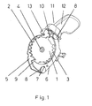
- the toothed pulley 1 carries on Extent of the holding teeth 2 and the fangs 3.
- the holding teeth 2 and the fangs 3 lie face each other and have different tooth contours.
- the holding teeth 2 have a pronounced sawtooth contour with a steep and a flat flank.
- In the middle of the toothed disc there is a bore 4 for receiving a central one Axis that is guided in the housing part 5.
- the sliding part 6 has two Slot guides 7 and can be moved with two guide pins 8 on the housing part 5 hinged. The sliding part 6 engages around the toothed disc 1 and is with two rigid jacks.
- the holding pawl 9 engages in the basic position shown into a tooth gap of the holding teeth 2 while the catch pawl 10 is disengaged the fangs 3 is located.
- the holding pawl 9 also has a sawtooth contour, which is coordinated with the contour of the holding teeth 2. The steep flank ensures a positive fixation of the toothed disc 1 in the basic position and the flat Flank facilitates the disengagement of the sliding part 6 when in the toothed disc 1 in Winding direction is switched.
- the release process is initiated with the actuating element 11 by the Swivel lever 12 pivots about the swivel axis 13 and a transmission contour on the actuating element 11 on a corresponding counter surface on the sliding part 1 acts.
- the counter surface on the sliding part 1 runs perpendicular to the toothed disk plane. If the pivot lever 12 is released again after actuation, so brings a bias spring, which is supported on the housing part 5, the pivot lever 12 and a return spring, the sliding part 6 back to the basic position.
- Fig. 2 shows the release mechanism in the catch position.
- the pivot lever 12 is in the actuation position and by means of the transmission contour, which acts on the counter surface 16 on the sliding part 6, the holding pawl 9 is moved out of the area of the holding teeth 2.
- the elongated holes 7 in the sliding part 6 and the guide pin 8 guide and limit the linear movement the sliding part 6.
- Fig. 3 shows the exploded view of the release device with its essential Components.
- the actuating element 11 with swivel lever 12 and transmission contour 14 is articulated on the housing part 5 by means of the pivot axis 13.
- the preload spring 15, which is supported on the housing part 5, holds the actuating element 11 in the basic position.
- the sliding part 6 engages around the toothed disc 1 and has a rigid pawl 9 and a rigid catch pawl 10, which, depending on the position of the Actuate the actuating element 11 in the holding teeth 2 or 3.
- With a Transfer contour on the actuator 11 is the release movement of the Actuating element 11 introduced into the sliding part 6 via the counter surface 16.
- the guide bolts 8 are fixed in the housing part 5 and ensure a linear movement the sliding part 6 along the slot guide 7.
- the sliding part 6 is returned to the basic position by means of the return spring 17 if this is the case Actuator 11 allowed.
- the cable spool 18 is non-rotatable with the toothed pulley 1 connected and rotates about the centering pin 19 through the hole 4 of the toothed disc 1 runs and is anchored to the housing part 5.
- Fig. 4 shows the release mechanism in plan view.
- the pivot lever 12 is not yet fully activated.
- the pawl 9 on the retaining tooth 2 is already partially disengaged.
- the cable pulley is biased by the cable pulley 1 and thus also the Holding pawl 9 or the sliding part 6 biased in the unwinding direction.
- the starting contour 20 of the slot of the slot guide 7 is designed so that the sliding part 6 when moving out of the basic position, along the guide pin 8 performs a slight evasive movement in the winding direction.
Landscapes
- Engineering & Computer Science (AREA)
- Mechanical Engineering (AREA)
- Chemical & Material Sciences (AREA)
- Combustion & Propulsion (AREA)
- Transportation (AREA)
- Mechanical Control Devices (AREA)
- Flexible Shafts (AREA)
- Gear-Shifting Mechanisms (AREA)
- Storing, Repeated Paying-Out, And Re-Storing Of Elongated Articles (AREA)
- Transmission Devices (AREA)
Abstract
Description
- Fig. 1
- zeigt den Freigabemechanismus in der Grundstellung
- Fig. 2
- zeigt den Freigabemechanismus in der Fangstellung
- Fig. 3
- zeigt eine Explosionsdarstellung mit den wesentlichen Komponenten
- Fig. 4
- zeigt den Freigabemechanismus in der Draufsicht
- 1
- Zahnscheibe
- 2
- Haltezahn
- 3
- Fangzahn
- 4
- Bohrung
- 5
- Gehäuseteil
- 6
- Schiebeteil
- 7
- Langlochführung
- 8
- Führungsbolzen
- 9
- Halteklinke
- 10
- Fangklinke
- 11
- Betätigungselement
- 12
- Schwenkhebel
- 13
- Schwenkachse
- 14
- Übertragungskontur
- 15
- Vorspannfeder
- 16
- Gegenfläche
- 17
- Rückholfeder
- 18
- Seilspule
- 19
- Zentrierbolzen
- 20
- Anlaufkontur
Claims (15)
- Freigabemechanismus zur Freigabe eines Zugmittels zur Steuerung von Fahrradgetrieben umfassend eine Seilspule 18 zum Aufwickeln des vorgespannten Schaltzuges, eine Auslösevorrichtung zum Fixieren bzw. Freigeben der durch den Schaltzug vorgespannten Seilspule 18 in Abwickelrichtung und einem Betätigungselement 11 zum Einleiten des Auslösevorganges sowie einem Gehäuseteil 5 zur Aufnahme und Führung der Bauteile
dadurch gekennzeichnet, dass die Auslösevorrichtung im wesentlichen aus einer, mit der Seilspule 18 verbundenen Zahnscheibe 1 und einem, mit gegenüberliegenden Klinken 9,10 ausgestatteten Schiebeteil 6 gebildet wird und dass die Klinken 9,10 während des Auslösevorganges wechselweise am Umfang der Zahnscheibe 1 eingreifen. - Freigabemechanismus nach Anspruch 1,
dadurch gekennzeichnet, dass das Schiebeteil 6 über mindestens eine starre Halte- 9 und Fangklinke 10 verfügt und federnd am Gehäuseteil 5 angelenkt ist, damit das Schiebeteil 6 aus der Fangstellung wieder in die Haltestellung zurückgeführt wird. - Freigabemechanismus nach Anspruch 1,
dadurch gekennzeichnet, dass das Schiebeteil 6, insbesondere mit mindestens einer Langlochführung 7 am Gehäuseteil 5 geführt wird und eine annähernd lineare Bewegung in der Zahnscheibenebene oder parallel zur Zahnscheibenebene ausführt. - Freigabemechanismus nach Anspruch 1,
dadurch gekennzeichnet, dass Mittel zur Erhöhung ausschließlich der Auslösekraft unter Nutzung der Seilzugspannung vorgesehen sind. - Freigabemechanismus nach Anspruch 4,
dadurch gekennzeichnet, dass das Langloch einer Langlochführung 7 in der Nähe der Halteklinke 9 mit einer Anlaufkontur 20, vorzugsweise mit einer Schräge oder einer Stufe ausgestattet ist, die bei Verschiebung des Schiebeteils 6 aus der Grundstellung heraus die Halteklinke 9 geringfügig gegen die Seilspannung bewegt, wodurch sich die momentane Auslösekraft erhöht. - Freigabemechanismus nach Anspruch 1,
dadurch gekennzeichnet, dass die Zahnscheibe 1 mit Halte- 2 und Fangzähnen 3 ausgestattet ist, die jeweils etwa um 180 Grad versetzt am Umfang angeordnet sind. - Freigabemechanismus nach Anspruch 1,
dadurch gekennzeichnet, dass die Haltezähne 2 mit verschiedenen Zahnflanken ausgestattet sind, vorzugsweise eine Sägezahnkontur aufweisen. - Freigabemechanismus nach Anspruch 1,
dadurch gekennzeichnet, dass die Freigabebewegung am Schiebeteil 6 mittels eines Betätigungselementes 11 eingeleitet wird und dass am Betätigungselement 11 eine geeignete Übertragungskontur 14 und am Schiebeteil 6 eine entsprechende Gegenfläche 16 vorgesehen ist, die eine nahezu verschleißfreie Übertragung der Freigabebewegung gewährleisten. - Freigabemechanismus nach Anspruch 8,
dadurch gekennzeichnet, dass die Übertragungskontur 14 und die Gegenfläche 16 im wesentlichen senkrecht zur Zahnscheibenebene angeordnet sind. - Freigabemechanismus nach Anspruch 8,
dadurch gekennzeichnet, dass das Betätigungselement 11 um eine, vom Gehäuseteil 5 gestützte Schwenkachse 13 schwenkt, die vorzugsweise parallel zur Ebene der Zahnscheibe 1 verläuft. - Freigabemechanismus nach Anspruch 8,
dadurch gekennzeichnet, dass das Betätigungselement 11 um eine, vom Gehäuseteil 5 gestützte Schwenkachse 13 schwenkt, die vorzugsweise senkrecht zur Zahnscheibenebene verläuft. - Freigabemechanismus nach den Ansprüchen 10 und 11,
dadurch gekennzeichnet, dass die Schwenkbewegung des Betätigungselementes 11 mittels der Übertragungskontur 14 und einer Gegenfläche 16 in eine Linearbewegung des Schiebeteils 6 umgeformt wird. - Freigabemechanismus nach Anspruch 1,
dadurch gekennzeichnet, dass das Betätigungselement 11 eine lineare Bewegung ausführt, die vorzugsweise annähernd parallel zur Zahnscheibenebene verläuft. - Freigabemechanismus nach den Ansprüchen 8 und 13,
dadurch gekennzeichnet, dass Schiebeteil 6 und Betätigungselement 11 ein gemeinsames Bauteil bilden oder mit einem Scharnier verbunden sind. - Freigabemechanismus nach Anspruch 2,
dadurch gekennzeichnet, dass das Schiebeteil 6 und die Rückholfeder 17 ein gemeinsames Bauteil bilden.
Applications Claiming Priority (2)
| Application Number | Priority Date | Filing Date | Title |
|---|---|---|---|
| DE10205278.6A DE10205278B4 (de) | 2002-02-08 | 2002-02-08 | Freigabemechanismus |
| DE10205278 | 2002-02-08 |
Publications (4)
| Publication Number | Publication Date |
|---|---|
| EP1334903A2 true EP1334903A2 (de) | 2003-08-13 |
| EP1334903A3 EP1334903A3 (de) | 2007-05-30 |
| EP1334903B1 EP1334903B1 (de) | 2008-11-26 |
| EP1334903B2 EP1334903B2 (de) | 2012-03-07 |
Family
ID=27588497
Family Applications (1)
| Application Number | Title | Priority Date | Filing Date |
|---|---|---|---|
| EP03000971A Expired - Lifetime EP1334903B2 (de) | 2002-02-08 | 2003-01-17 | Freigabemechanismus für Triggerschalter |
Country Status (5)
| Country | Link |
|---|---|
| US (1) | US7194931B2 (de) |
| EP (1) | EP1334903B2 (de) |
| CN (1) | CN100348455C (de) |
| DE (2) | DE10205278B4 (de) |
| TW (1) | TWI248412B (de) |
Cited By (1)
| Publication number | Priority date | Publication date | Assignee | Title |
|---|---|---|---|---|
| EP1366981A3 (de) * | 2002-05-31 | 2007-09-05 | SRAM Deutschland GmbH | Freigabemechanismus für Triggerschalter |
Families Citing this family (13)
| Publication number | Priority date | Publication date | Assignee | Title |
|---|---|---|---|---|
| US7882763B2 (en) * | 2004-07-23 | 2011-02-08 | Shimano, Inc. | Shift control device for a bicycle transmission |
| US9809278B2 (en) * | 2004-09-28 | 2017-11-07 | Shimano, Inc. | Apparatus for reducing an engaging force of an engaging member |
| DE102004051883B4 (de) * | 2004-10-26 | 2020-09-10 | Sram Deutschland Gmbh | Schaltermechanismus für einen Schrittschalter für Fahrräder |
| US7779718B2 (en) * | 2005-03-03 | 2010-08-24 | Sram, Llc | Bicycle shifter |
| US7721621B2 (en) * | 2005-11-04 | 2010-05-25 | Shimano Inc. | Bicycle shift control mechanism |
| US9227689B2 (en) | 2008-01-08 | 2016-01-05 | Shimano Inc. | Bicycle shift operating device |
| DE102008048134C5 (de) * | 2008-09-20 | 2018-09-27 | Sram Deutschland Gmbh | Schalter zur Betätigung eines Getriebes an einem Fahrrad |
| CN102582780B (zh) * | 2012-02-17 | 2013-04-24 | 中山新宝精密科技有限公司 | 具有多方向释放操作的自行车变速换挡机构 |
| US8746105B2 (en) * | 2012-02-24 | 2014-06-10 | Shimano Inc. | Bicycle operating device |
| DE102013216932A1 (de) * | 2013-08-26 | 2015-02-26 | Sram Deutschland Gmbh | Halte- und Freigabemechanik zum Halten und Freigeben einer Seilaufnahmevorrichtung |
| CN106005230A (zh) * | 2016-06-29 | 2016-10-12 | 麦志成 | 一种自行车无级变速器 |
| CN106926969B (zh) * | 2017-03-16 | 2022-06-21 | 珠海蓝图控制器科技有限公司 | 一种自行车换挡器 |
| CN108928430B (zh) * | 2018-08-28 | 2023-08-11 | 珠海蓝图运动科技股份有限公司 | 一种自行车操作机构 |
Citations (1)
| Publication number | Priority date | Publication date | Assignee | Title |
|---|---|---|---|---|
| DE9015515U1 (de) | 1990-11-13 | 1991-03-28 | Fichtel & Sachs Ag, 8720 Schweinfurt | Schrittschalter zur Steuerung von Fahrradgetrieben |
Family Cites Families (26)
| Publication number | Priority date | Publication date | Assignee | Title |
|---|---|---|---|---|
| CH248670A (de) | 1946-02-26 | 1947-05-15 | Velosfabrik Cosmos B Schild & | Schaltvorrichtung für Wechselgetriebe, insbesondere von Fahr- und Motorrädern. |
| GB645912A (en) * | 1948-05-26 | 1950-11-08 | Birmingham Small Arms Co Ltd | Improvements in and relating to control-lever mechanism |
| GB2169065B (en) † | 1984-12-28 | 1987-12-23 | Sturmey Archer Ltd | Indexing mechanisms and controls embodying the same |
| JP2594270B2 (ja) * | 1987-03-20 | 1997-03-26 | 株式会社シマノ | 自転車用変速操作装置 |
| US5012692A (en) * | 1988-09-24 | 1991-05-07 | Shimano Industrial Company Limited | Change-speed lever apparatus for use in bicycle |
| JPH0313297U (de) * | 1989-06-26 | 1991-02-12 | ||
| JP3065656B2 (ja) * | 1990-11-14 | 2000-07-17 | 株式会社シマノ | 自転車用変速操作装置 |
| JPH04260889A (ja) * | 1991-02-13 | 1992-09-16 | Maeda Kogyo Kk | 自転車用変速操作装置 |
| JP3245188B2 (ja) * | 1991-04-19 | 2002-01-07 | 株式会社シマノ | 自転車用変速操作装置 |
| US5355745A (en) * | 1992-08-12 | 1994-10-18 | Chuan Fei Industrial Limited Company | Bicycle speed controller |
| JP2601207Y2 (ja) * | 1992-12-28 | 1999-11-15 | 株式会社シマノ | 自転車用の変速操作装置 |
| JPH06239287A (ja) * | 1993-02-12 | 1994-08-30 | Mori San Tsuaa:Kk | 自転車用変速操作装置 |
| FR2701917B1 (fr) * | 1993-02-26 | 1995-07-07 | Sachs Ind Sa | Dispositif a deux organes de commande pour derailleur de cycle. |
| IT1261550B (it) † | 1993-04-20 | 1996-05-23 | Antonio Romano | Dispositivo di comando del cambio di una bicicletta. |
| US5361645A (en) * | 1993-08-24 | 1994-11-08 | Industrial Technology Research Institute | Shift lever apparatus for use in bicycle |
| JP3449577B2 (ja) * | 1995-05-26 | 2003-09-22 | 株式会社シマノ | 自転車用ブレーキ及び変速操作装置 |
| US5673594A (en) * | 1996-01-03 | 1997-10-07 | Industrial Technology Research Institute | Speed change lever apparatus for use in bicycles |
| US5730030A (en) † | 1996-01-19 | 1998-03-24 | Shimano, Inc. | Shifting apparatus for bicycles having a brake operating unit disposed between first and second shifting levers |
| TW378183B (en) † | 1996-02-14 | 2000-01-01 | Shimano Kk | Bicycle shift levers which surround a handlebar |
| US5829313A (en) * | 1997-01-13 | 1998-11-03 | Shimano Inc. | Bicycle derailleur shifting mechanism having indexing configured for use with variety of chain sprocket sets |
| US6095309A (en) * | 1998-11-12 | 2000-08-01 | At Design Inc. | Cycle handlebar actuator |
| DE19915336A1 (de) † | 1999-04-03 | 2000-10-05 | Sram De Gmbh | Schalter für ein Fahrradgetriebe |
| DE10013262A1 (de) * | 2000-03-17 | 2001-09-20 | Sram De Gmbh | Einwegkraftübertragung |
| US6450060B1 (en) † | 2000-03-17 | 2002-09-17 | Shimano, Inc. | Bicycle shift device having a linearly sliding shift lever operated by a pivoting cover |
| DE10016581A1 (de) * | 2000-04-04 | 2001-10-11 | Sram De Gmbh | Schrittschalter |
| ITTO20010011A1 (it) * | 2001-01-11 | 2002-07-11 | Campagnolo Srl | Gruppo integrato di comando del cambio e del freno per una bicicletta. |
-
2002
- 2002-02-08 DE DE10205278.6A patent/DE10205278B4/de not_active Expired - Lifetime
-
2003
- 2003-01-17 DE DE50310819T patent/DE50310819D1/de not_active Expired - Lifetime
- 2003-01-17 EP EP03000971A patent/EP1334903B2/de not_active Expired - Lifetime
- 2003-01-30 CN CNB031021018A patent/CN100348455C/zh not_active Expired - Lifetime
- 2003-02-06 TW TW092102403A patent/TWI248412B/zh not_active IP Right Cessation
- 2003-02-10 US US10/361,543 patent/US7194931B2/en not_active Expired - Lifetime
Patent Citations (1)
| Publication number | Priority date | Publication date | Assignee | Title |
|---|---|---|---|---|
| DE9015515U1 (de) | 1990-11-13 | 1991-03-28 | Fichtel & Sachs Ag, 8720 Schweinfurt | Schrittschalter zur Steuerung von Fahrradgetrieben |
Cited By (1)
| Publication number | Priority date | Publication date | Assignee | Title |
|---|---|---|---|---|
| EP1366981A3 (de) * | 2002-05-31 | 2007-09-05 | SRAM Deutschland GmbH | Freigabemechanismus für Triggerschalter |
Also Published As
| Publication number | Publication date |
|---|---|
| DE10205278B4 (de) | 2019-03-14 |
| TW200306266A (en) | 2003-11-16 |
| EP1334903B1 (de) | 2008-11-26 |
| DE10205278A1 (de) | 2003-08-21 |
| EP1334903B2 (de) | 2012-03-07 |
| DE50310819D1 (de) | 2009-01-08 |
| CN1436696A (zh) | 2003-08-20 |
| CN100348455C (zh) | 2007-11-14 |
| US7194931B2 (en) | 2007-03-27 |
| TWI248412B (en) | 2006-02-01 |
| US20030167876A1 (en) | 2003-09-11 |
| EP1334903A3 (de) | 2007-05-30 |
Similar Documents
| Publication | Publication Date | Title |
|---|---|---|
| EP0697826B1 (de) | Schuhverschluss | |
| EP1019281B1 (de) | Schalter für fahrradgetriebe | |
| EP1334903A2 (de) | Freigabemechanismus für Triggerschalter | |
| EP1366981A2 (de) | Freigabemechanismus für Triggerschalter | |
| DE102016113069A1 (de) | Lenkrolle mit einem Laufrad | |
| EP2165924A1 (de) | Schalter für ein Fahrradgetriebe | |
| EP1468631B1 (de) | Dämpfungsvorrichtung für bewegbare Möbelteile | |
| DE10358438A1 (de) | Schaltermechanismus für Fahrradgetriebe | |
| EP0111790B1 (de) | Fensteraufsteller | |
| DE102006012424B4 (de) | Spanneinrichtung an einem Ständer zum Aufspannen eines stabförmigen Teiles, insbesondere eines Christbaumes, und Ständer mit Spanneinrichtung | |
| EP2025853B1 (de) | Mitnehmervorrichtung für eine Torantriebsvorrichtung, eine solche Torantriebsvorrichtung und ein Tor | |
| DE3924210C2 (de) | Türverriegelung | |
| EP2927416B1 (de) | Sicherheitsschloss | |
| EP3009299B1 (de) | Spannratsche | |
| DE10213450B4 (de) | Freigabeeinrichtung für Triggerschalter | |
| DE102009006497A1 (de) | Schloss, insbesondere Schubriegelschloss, mit erhöhter Schutzwirkung | |
| EP1470951A2 (de) | Ratschenartige Verstellvorrichtung | |
| DE102015102757B4 (de) | Beschlaganordnung | |
| DE4128112A1 (de) | Sperrvorrichtung zwischen motor und getriebe | |
| EP1947289B1 (de) | Kupplung für eine Wickelwelle eines Springrollos | |
| DE4316340C1 (de) | Schuhverschluß | |
| DE102004064265C5 (de) | Schaltmechanismus für einen Triggerschalter für Fahrräder | |
| DE3827376C2 (de) | ||
| DE102007014934A1 (de) | Antriebsvorrichtung für ein Verstellsystem in einem Kraftfahrzeug und in einem Kraftfahrzeug angeordneter Träger | |
| DE102005002549B4 (de) | Spanneinrichtung an einem Ständer zum Aufspannen eines stabförmigen Teiles; insbesondere eines Christbaumes; und Ständer mit Spanneinrichtung |
Legal Events
| Date | Code | Title | Description |
|---|---|---|---|
| PUAI | Public reference made under article 153(3) epc to a published international application that has entered the european phase |
Free format text: ORIGINAL CODE: 0009012 |
|
| AK | Designated contracting states |
Designated state(s): AT BE BG CH CY CZ DE DK EE ES FI FR GB GR HU IE IT LI LU MC NL PT SE SI SK TR |
|
| AX | Request for extension of the european patent |
Extension state: AL LT LV MK RO |
|
| PUAL | Search report despatched |
Free format text: ORIGINAL CODE: 0009013 |
|
| AK | Designated contracting states |
Kind code of ref document: A3 Designated state(s): AT BE BG CH CY CZ DE DK EE ES FI FR GB GR HU IE IT LI LU MC NL PT SE SI SK TR |
|
| AX | Request for extension of the european patent |
Extension state: AL LT LV MK RO |
|
| 17P | Request for examination filed |
Effective date: 20070827 |
|
| AKX | Designation fees paid |
Designated state(s): DE FR NL |
|
| GRAP | Despatch of communication of intention to grant a patent |
Free format text: ORIGINAL CODE: EPIDOSNIGR1 |
|
| GRAS | Grant fee paid |
Free format text: ORIGINAL CODE: EPIDOSNIGR3 |
|
| GRAA | (expected) grant |
Free format text: ORIGINAL CODE: 0009210 |
|
| AK | Designated contracting states |
Kind code of ref document: B1 Designated state(s): DE FR NL |
|
| REF | Corresponds to: |
Ref document number: 50310819 Country of ref document: DE Date of ref document: 20090108 Kind code of ref document: P |
|
| PLBI | Opposition filed |
Free format text: ORIGINAL CODE: 0009260 |
|
| 26 | Opposition filed |
Opponent name: SHIMANO INC. Effective date: 20090825 |
|
| PLAX | Notice of opposition and request to file observation + time limit sent |
Free format text: ORIGINAL CODE: EPIDOSNOBS2 |
|
| NLR1 | Nl: opposition has been filed with the epo |
Opponent name: SHIMANO INC. |
|
| PLAF | Information modified related to communication of a notice of opposition and request to file observations + time limit |
Free format text: ORIGINAL CODE: EPIDOSCOBS2 |
|
| PLBB | Reply of patent proprietor to notice(s) of opposition received |
Free format text: ORIGINAL CODE: EPIDOSNOBS3 |
|
| PUAH | Patent maintained in amended form |
Free format text: ORIGINAL CODE: 0009272 |
|
| STAA | Information on the status of an ep patent application or granted ep patent |
Free format text: STATUS: PATENT MAINTAINED AS AMENDED |
|
| 27A | Patent maintained in amended form |
Effective date: 20120307 |
|
| AK | Designated contracting states |
Kind code of ref document: B2 Designated state(s): DE FR NL |
|
| REG | Reference to a national code |
Ref country code: NL Ref legal event code: T3 |
|
| REG | Reference to a national code |
Ref country code: DE Ref legal event code: R102 Ref document number: 50310819 Country of ref document: DE Effective date: 20120307 |
|
| REG | Reference to a national code |
Ref country code: FR Ref legal event code: PLFP Year of fee payment: 14 |
|
| REG | Reference to a national code |
Ref country code: FR Ref legal event code: PLFP Year of fee payment: 15 |
|
| REG | Reference to a national code |
Ref country code: FR Ref legal event code: PLFP Year of fee payment: 16 |
|
| PGFP | Annual fee paid to national office [announced via postgrant information from national office to epo] |
Ref country code: DE Payment date: 20220131 Year of fee payment: 20 |
|
| PGFP | Annual fee paid to national office [announced via postgrant information from national office to epo] |
Ref country code: NL Payment date: 20220119 Year of fee payment: 20 Ref country code: FR Payment date: 20220119 Year of fee payment: 20 |
|
| REG | Reference to a national code |
Ref country code: DE Ref legal event code: R071 Ref document number: 50310819 Country of ref document: DE |
|
| REG | Reference to a national code |
Ref country code: NL Ref legal event code: MK Effective date: 20230116 |