EP1335149A1 - Piston d'amortisseur pour équipements hydrauliques - Google Patents
Piston d'amortisseur pour équipements hydrauliques Download PDFInfo
- Publication number
- EP1335149A1 EP1335149A1 EP03000781A EP03000781A EP1335149A1 EP 1335149 A1 EP1335149 A1 EP 1335149A1 EP 03000781 A EP03000781 A EP 03000781A EP 03000781 A EP03000781 A EP 03000781A EP 1335149 A1 EP1335149 A1 EP 1335149A1
- Authority
- EP
- European Patent Office
- Prior art keywords
- piston
- hydraulic
- damper piston
- damper
- cover
- Prior art date
- Legal status (The legal status is an assumption and is not a legal conclusion. Google has not performed a legal analysis and makes no representation as to the accuracy of the status listed.)
- Granted
Links
Images


Classifications
-
- F—MECHANICAL ENGINEERING; LIGHTING; HEATING; WEAPONS; BLASTING
- F16—ENGINEERING ELEMENTS AND UNITS; GENERAL MEASURES FOR PRODUCING AND MAINTAINING EFFECTIVE FUNCTIONING OF MACHINES OR INSTALLATIONS; THERMAL INSULATION IN GENERAL
- F16F—SPRINGS; SHOCK-ABSORBERS; MEANS FOR DAMPING VIBRATION
- F16F9/00—Springs, vibration-dampers, shock-absorbers, or similarly-constructed movement-dampers using a fluid or the equivalent as damping medium
- F16F9/32—Details
- F16F9/34—Special valve constructions; Shape or construction of throttling passages
- F16F9/348—Throttling passages in the form of annular discs or other plate-like elements which may or may not have a spring action, operating in opposite directions or singly, e.g. annular discs positioned on top of the valve or piston body
- F16F9/3481—Throttling passages in the form of annular discs or other plate-like elements which may or may not have a spring action, operating in opposite directions or singly, e.g. annular discs positioned on top of the valve or piston body characterised by shape or construction of throttling passages in piston
-
- F—MECHANICAL ENGINEERING; LIGHTING; HEATING; WEAPONS; BLASTING
- F16—ENGINEERING ELEMENTS AND UNITS; GENERAL MEASURES FOR PRODUCING AND MAINTAINING EFFECTIVE FUNCTIONING OF MACHINES OR INSTALLATIONS; THERMAL INSULATION IN GENERAL
- F16F—SPRINGS; SHOCK-ABSORBERS; MEANS FOR DAMPING VIBRATION
- F16F9/00—Springs, vibration-dampers, shock-absorbers, or similarly-constructed movement-dampers using a fluid or the equivalent as damping medium
- F16F9/32—Details
- F16F9/34—Special valve constructions; Shape or construction of throttling passages
- F16F9/348—Throttling passages in the form of annular discs or other plate-like elements which may or may not have a spring action, operating in opposite directions or singly, e.g. annular discs positioned on top of the valve or piston body
- F16F9/3482—Throttling passages in the form of annular discs or other plate-like elements which may or may not have a spring action, operating in opposite directions or singly, e.g. annular discs positioned on top of the valve or piston body the annular discs being incorporated within the valve or piston body
Definitions
- the invention relates to a damper piston for hydraulic devices, in particular for hydraulic vibration dampers on motor vehicles, according to the preamble of claim 1.
- Hydraulic damper pistons are used to control the flow a hydraulic fluid, especially a hydraulic oil, with vibration dampers to dampen for motor vehicles. At damper pistons for hydraulic vibration damper on motor vehicles, this dampens the suspension of the wheel bearings.
- damper pistons are known, for example, from EP 0 275 368 A1.
- the damper piston according to the invention has a very comfortable damping. He can advantageously not only used as a main piston in a shock absorber but also as a damper piston with a bypass inside or outside the shock absorber and also as a bottom valve in a two-pipe shock absorber.
- shock absorbers for motor vehicles of modern design are often with controllable or equipped with adjustable bypasses. This makes it possible, the damping properties to adapt the vibration damper the respective requirements during driving and still ensure a safe road holding of the motor vehicle is guaranteed.
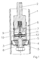
- a shock absorber Fig. 1. It is here to a monotube shock absorber with a shock absorber tube 1, with a damping fluid is filled. At the end of an oscillating in the shock absorber tube and diving Piston rod 2 is mounted a damper piston system.
- the damper piston system has a classic working piston 3, which has openings 4, the one side over spring disc packages 5, which also act as check valves covered are.
- the damper piston system further comprises a bypass device 6.
- the bypass device 6 consists of a controllable inlet channel 7 and a centric by the working piston 3 extending further inlet channel 8.
- the regulation of Flow takes place on the one hand via a control slide 9 and the other over a damper piston 10 which has as well as the working piston 3 breakthroughs, the reciprocally on both sides by means of spring disk packages 11, 12, which also serve as check valves act, be closed.
- the damper piston 10 is similar to the working piston 3 with many small Breakthroughs formed, which causes the disadvantages described above.
- FIGS. 2 to 4 show a damper piston 10 of the type according to the invention.
- This damper piston 10 as the damper piston 10 in Fig. 1, the influence the bypass flow. He lies with his outer coat in the pot-shaped here Bypass issued 6 and has two crescent-shaped openings 13, 14 on.
- the spring disk packages 11, 12 close one-sided and mutually top and below the openings 13, 14.
- the spring disk packages 11, 12 are eccentric arranged and in the exemplary embodiment via screws 15 with the piston body 16th screwed.
- FIG. 3 and 4 are for better understanding the spring disk packages 11 and 12th not shown.
- the spring disc package 11, not shown, is located on the rotating Bulge 17 on.
- the threads 18 for insertion of the screws 15 are each centric to the bead 17.
- a recess 19 is provided in the in the representation of FIG. 3 and 4, the opening 14 opens.
- the other breakthrough 13 is not due to the eccentric arrangement of the spring disk packages 11, 12 Spring washers covered and thus granted a free inlet.
- damper piston 10 can not only for the influence of Bypasses are used. He can in the same way as working piston directly at the Be attached piston rod 2. For this, the piston intake must of course cup-shaped to be able to hold the damper piston can. In the same Way is the damper piston 10 of the invention as a bottom valve in a two-pipe damper can be used or as a control piston for an outside of the shock absorber arranged Control unit.
Landscapes
- Engineering & Computer Science (AREA)
- General Engineering & Computer Science (AREA)
- Mechanical Engineering (AREA)
- Fluid-Damping Devices (AREA)
Applications Claiming Priority (2)
| Application Number | Priority Date | Filing Date | Title |
|---|---|---|---|
| DE10206104 | 2002-02-13 | ||
| DE10206104A DE10206104C1 (de) | 2002-02-13 | 2002-02-13 | Dämpferkolben für hydraulische Einrichtungen |
Publications (2)
| Publication Number | Publication Date |
|---|---|
| EP1335149A1 true EP1335149A1 (fr) | 2003-08-13 |
| EP1335149B1 EP1335149B1 (fr) | 2006-03-22 |
Family
ID=7713812
Family Applications (1)
| Application Number | Title | Priority Date | Filing Date |
|---|---|---|---|
| EP03000781A Expired - Lifetime EP1335149B1 (fr) | 2002-02-13 | 2003-01-14 | Piston d'amortisseur pour équipements hydrauliques |
Country Status (4)
| Country | Link |
|---|---|
| US (1) | US6974004B2 (fr) |
| EP (1) | EP1335149B1 (fr) |
| DE (2) | DE10206104C1 (fr) |
| ES (1) | ES2257603T3 (fr) |
Cited By (3)
| Publication number | Priority date | Publication date | Assignee | Title |
|---|---|---|---|---|
| EP1544498A1 (fr) * | 2003-12-20 | 2005-06-22 | DaimlerChrysler AG | Dispositif amortisseur pour un véhicule |
| CN104583639A (zh) * | 2012-08-27 | 2015-04-29 | 尤利乌斯·布卢姆有限公司 | 用于可动家具部件的缓冲装置 |
| EP4582717A4 (fr) * | 2022-08-29 | 2026-07-08 | Saic Motor Corp Ltd | Ensemble noyau de soupape et amortisseur à commande électronique intégré le comprenant |
Families Citing this family (6)
| Publication number | Priority date | Publication date | Assignee | Title |
|---|---|---|---|---|
| DE10309743B3 (de) * | 2003-03-06 | 2004-05-27 | Thyssenkrupp Bilstein Gmbh | Hydraulischer Schwingungsdämpfer für Kraftfahrzeuge |
| DE102012210459B3 (de) * | 2012-06-21 | 2013-10-10 | Zf Friedrichshafen Ag | Verstellbare Dämpfventileinrichtung |
| DE102012016711A1 (de) * | 2012-08-22 | 2014-02-27 | Volkswagen Aktiengesellschaft | Ventilkolbenanordnung für einen Schalt-Schwingungsdämpfer |
| FI125755B (fi) * | 2014-03-05 | 2016-02-15 | Dynaset Oy | Hydraulisessa järjestelmässä käytettävä vaimennin |
| WO2021030807A1 (fr) | 2019-08-15 | 2021-02-18 | Somark Group Pty Ltd | Cartouche d'insertion d'étiquette rfid |
| DE102024122226A1 (de) * | 2024-08-04 | 2026-02-05 | Thyssenkrupp Ag | Schieberelement, Dämpferventil und Schwingungsdämpfer |
Citations (6)
| Publication number | Priority date | Publication date | Assignee | Title |
|---|---|---|---|---|
| US3003596A (en) * | 1955-02-21 | 1961-10-10 | Bourcier Christian Marie Louis | Shock absorbers |
| US3113644A (en) * | 1960-06-18 | 1963-12-10 | Fichtel & Sachs Ag | Shock absorber |
| DE1249100B (fr) * | 1959-02-17 | 1967-08-31 | ||
| DE2109398A1 (de) * | 1971-02-27 | 1972-09-07 | Fichtel & Sachs Ag | Stoßdämpferventil mit kontinuierlichem Übergang |
| EP0275368A2 (fr) | 1987-01-21 | 1988-07-27 | August Bilstein GmbH & Co. KG | Piston d'amortisseur de chocs, particulièrement d'amortisseur à un tube pour véhicule automobile |
| DE4433056A1 (de) * | 1994-09-16 | 1996-03-28 | Fichtel & Sachs Ag | Schwingungsdämpfer, insbesondere für Kraftfahrzeuge |
Family Cites Families (8)
| Publication number | Priority date | Publication date | Assignee | Title |
|---|---|---|---|---|
| DE716726C (de) * | 1939-04-09 | 1942-01-28 | Audi Nsu Auto Union Ag | Stossdaempfer, vorzugsweise fuer Kraftfahrzeuge |
| DE899302C (de) * | 1942-01-03 | 1953-12-10 | Hemscheidt Maschf Hermann | UEberdruckventil, insbesondere fuer Fluessigkeitsstossdaempfer von Kraftfahrzeugen |
| DE3010463C2 (de) * | 1980-03-19 | 1982-05-06 | Witzenmann GmbH, Metallschlauch-Fabrik Pforzheim, 7530 Pforzheim | Hydraulische Stoßbremse für Rohrleitungssysteme |
| DE3518327A1 (de) * | 1985-05-22 | 1986-11-27 | Boge Gmbh, 5208 Eitorf | Hydraulischer, verstellbarer schwingungsdaempfer |
| JP2958333B2 (ja) * | 1989-11-24 | 1999-10-06 | カヤバ工業株式会社 | 油圧緩衝器のバルブ装置 |
| JPH03196703A (ja) * | 1989-12-26 | 1991-08-28 | Mazda Motor Corp | 車両用ガラスアンテナ |
| JPH03199733A (ja) * | 1989-12-27 | 1991-08-30 | Kayaba Ind Co Ltd | 油圧緩衝器のバルブ装置 |
| US5219430A (en) * | 1990-03-13 | 1993-06-15 | Aerospatiale Societe Nationale Industrielle | Hydraulic damper and elastic-return strut comprising such a damper |
-
2002
- 2002-02-13 DE DE10206104A patent/DE10206104C1/de not_active Expired - Lifetime
-
2003
- 2003-01-14 DE DE50302691T patent/DE50302691D1/de not_active Expired - Lifetime
- 2003-01-14 ES ES03000781T patent/ES2257603T3/es not_active Expired - Lifetime
- 2003-01-14 EP EP03000781A patent/EP1335149B1/fr not_active Expired - Lifetime
- 2003-02-11 US US10/365,001 patent/US6974004B2/en not_active Expired - Lifetime
Patent Citations (6)
| Publication number | Priority date | Publication date | Assignee | Title |
|---|---|---|---|---|
| US3003596A (en) * | 1955-02-21 | 1961-10-10 | Bourcier Christian Marie Louis | Shock absorbers |
| DE1249100B (fr) * | 1959-02-17 | 1967-08-31 | ||
| US3113644A (en) * | 1960-06-18 | 1963-12-10 | Fichtel & Sachs Ag | Shock absorber |
| DE2109398A1 (de) * | 1971-02-27 | 1972-09-07 | Fichtel & Sachs Ag | Stoßdämpferventil mit kontinuierlichem Übergang |
| EP0275368A2 (fr) | 1987-01-21 | 1988-07-27 | August Bilstein GmbH & Co. KG | Piston d'amortisseur de chocs, particulièrement d'amortisseur à un tube pour véhicule automobile |
| DE4433056A1 (de) * | 1994-09-16 | 1996-03-28 | Fichtel & Sachs Ag | Schwingungsdämpfer, insbesondere für Kraftfahrzeuge |
Cited By (4)
| Publication number | Priority date | Publication date | Assignee | Title |
|---|---|---|---|---|
| EP1544498A1 (fr) * | 2003-12-20 | 2005-06-22 | DaimlerChrysler AG | Dispositif amortisseur pour un véhicule |
| CN104583639A (zh) * | 2012-08-27 | 2015-04-29 | 尤利乌斯·布卢姆有限公司 | 用于可动家具部件的缓冲装置 |
| CN104583639B (zh) * | 2012-08-27 | 2016-03-16 | 尤利乌斯·布卢姆有限公司 | 用于可动家具部件的缓冲装置和配置装置 |
| EP4582717A4 (fr) * | 2022-08-29 | 2026-07-08 | Saic Motor Corp Ltd | Ensemble noyau de soupape et amortisseur à commande électronique intégré le comprenant |
Also Published As
| Publication number | Publication date |
|---|---|
| DE50302691D1 (de) | 2006-05-11 |
| DE10206104C1 (de) | 2003-05-28 |
| US6974004B2 (en) | 2005-12-13 |
| US20030150679A1 (en) | 2003-08-14 |
| ES2257603T3 (es) | 2006-08-01 |
| EP1335149B1 (fr) | 2006-03-22 |
Similar Documents
| Publication | Publication Date | Title |
|---|---|---|
| DE3720584C2 (de) | Trennkörper | |
| DE19749356B4 (de) | Zweistufiger Stoßdämpfer mit hubabhängiger Dämpfung | |
| EP0405123B1 (fr) | Soupape électromagnétique à deux sens pour réglage d'une dérivation | |
| DE102008045492B4 (de) | Federdämpfungssystem mit mindestens zwei Gasfedern | |
| EP1133648B1 (fr) | Clapet de fond destinee a un amortisseur de chocs a deux tuyaux d'un vehicule automobile | |
| EP1745222B1 (fr) | Ressort pneumatique | |
| EP0926384A3 (fr) | Piston pour un amortisseur de vibrations hydraulique | |
| DE102016221980A1 (de) | Dämpfervorrichtung für ein Fahrzeug sowie Fahrzeug mit der Dämpfervorrichtung | |
| DE112004001829B4 (de) | Extratragbereich für Ventilteller | |
| DE102010022286A1 (de) | Luftdämpfungsmechanismus für einen Pneumatikzylinder | |
| EP1589254B1 (fr) | Amortisseur de chocs à amortissement variable avec amplitude | |
| EP1335149B1 (fr) | Piston d'amortisseur pour équipements hydrauliques | |
| EP1431608A2 (fr) | Amortisseur de vibrations avec une force d'amortissement proportionnelle à l'amplitude | |
| DE102005008162B3 (de) | Dämpfventil | |
| DE2364855A1 (de) | Stossdaempfer | |
| DE2629816C2 (de) | Lamellendämpfer mit veränderlicher Anpreßkraft | |
| DE10306564B3 (de) | Dämpfer | |
| DE102017216662B4 (de) | Dämpfungsanordnung für einen Schwingungsdämpfer eines Kraftfahrzeugs | |
| DE69001267T2 (de) | Hydropneumatische aufhaengung mit veraenderlicher daempfung und steifheit. | |
| EP1106403A2 (fr) | Amortisseur de vibrations réglable | |
| DE69830692T2 (de) | Hydraulischer Stossdämpfer | |
| DE3737252A1 (de) | Hydraulisch gedaempftes elastomer-metall-lager | |
| DE2139942B1 (de) | Schwingungsdämpfer, insbesondere für Kraftfahrzeuge, mit frequenzabhängig zuschaltbarem Zusatzdämpfventil | |
| DE10321351A1 (de) | Einrichtung zur amplitudenabhängigen Dämpfung von Stößen | |
| DE1094534B (de) | Regelbarer Stossdaempfer fuer Fahrzeuge |
Legal Events
| Date | Code | Title | Description |
|---|---|---|---|
| PUAI | Public reference made under article 153(3) epc to a published international application that has entered the european phase |
Free format text: ORIGINAL CODE: 0009012 |
|
| AK | Designated contracting states |
Designated state(s): AT BE BG CH CY CZ DE DK EE ES FI FR GB GR HU IE IT LI LU MC NL PT SE SI SK TR |
|
| AX | Request for extension of the european patent |
Extension state: AL LT LV MK RO |
|
| 17P | Request for examination filed |
Effective date: 20030710 |
|
| 17Q | First examination report despatched |
Effective date: 20031023 |
|
| AKX | Designation fees paid |
Designated state(s): DE ES FR GB IT |
|
| GRAP | Despatch of communication of intention to grant a patent |
Free format text: ORIGINAL CODE: EPIDOSNIGR1 |
|
| GRAS | Grant fee paid |
Free format text: ORIGINAL CODE: EPIDOSNIGR3 |
|
| GRAA | (expected) grant |
Free format text: ORIGINAL CODE: 0009210 |
|
| AK | Designated contracting states |
Kind code of ref document: B1 Designated state(s): DE ES FR GB IT |
|
| PG25 | Lapsed in a contracting state [announced via postgrant information from national office to epo] |
Ref country code: IT Free format text: LAPSE BECAUSE OF FAILURE TO SUBMIT A TRANSLATION OF THE DESCRIPTION OR TO PAY THE FEE WITHIN THE PRESCRIBED TIME-LIMIT;WARNING: LAPSES OF ITALIAN PATENTS WITH EFFECTIVE DATE BEFORE 2007 MAY HAVE OCCURRED AT ANY TIME BEFORE 2007. THE CORRECT EFFECTIVE DATE MAY BE DIFFERENT FROM THE ONE RECORDED. Effective date: 20060322 |
|
| REG | Reference to a national code |
Ref country code: GB Ref legal event code: FG4D Free format text: NOT ENGLISH |
|
| GBT | Gb: translation of ep patent filed (gb section 77(6)(a)/1977) |
Effective date: 20060322 |
|
| RAP2 | Party data changed (patent owner data changed or rights of a patent transferred) |
Owner name: THYSSENKRUPP BILSTEIN SUSPENSION GMBH |
|
| REF | Corresponds to: |
Ref document number: 50302691 Country of ref document: DE Date of ref document: 20060511 Kind code of ref document: P |
|
| REG | Reference to a national code |
Ref country code: ES Ref legal event code: FG2A Ref document number: 2257603 Country of ref document: ES Kind code of ref document: T3 |
|
| ET | Fr: translation filed | ||
| PLBE | No opposition filed within time limit |
Free format text: ORIGINAL CODE: 0009261 |
|
| STAA | Information on the status of an ep patent application or granted ep patent |
Free format text: STATUS: NO OPPOSITION FILED WITHIN TIME LIMIT |
|
| 26N | No opposition filed |
Effective date: 20061227 |
|
| REG | Reference to a national code |
Ref country code: FR Ref legal event code: PLFP Year of fee payment: 14 |
|
| REG | Reference to a national code |
Ref country code: FR Ref legal event code: PLFP Year of fee payment: 15 |
|
| PGFP | Annual fee paid to national office [announced via postgrant information from national office to epo] |
Ref country code: FR Payment date: 20170120 Year of fee payment: 15 |
|
| PGFP | Annual fee paid to national office [announced via postgrant information from national office to epo] |
Ref country code: GB Payment date: 20170119 Year of fee payment: 15 |
|
| PGFP | Annual fee paid to national office [announced via postgrant information from national office to epo] |
Ref country code: ES Payment date: 20170113 Year of fee payment: 15 Ref country code: IT Payment date: 20170124 Year of fee payment: 15 |
|
| GBPC | Gb: european patent ceased through non-payment of renewal fee |
Effective date: 20180114 |
|
| PG25 | Lapsed in a contracting state [announced via postgrant information from national office to epo] |
Ref country code: FR Free format text: LAPSE BECAUSE OF NON-PAYMENT OF DUE FEES Effective date: 20180131 |
|
| REG | Reference to a national code |
Ref country code: FR Ref legal event code: ST Effective date: 20180928 |
|
| PG25 | Lapsed in a contracting state [announced via postgrant information from national office to epo] |
Ref country code: GB Free format text: LAPSE BECAUSE OF NON-PAYMENT OF DUE FEES Effective date: 20180114 |
|
| PG25 | Lapsed in a contracting state [announced via postgrant information from national office to epo] |
Ref country code: IT Free format text: LAPSE BECAUSE OF NON-PAYMENT OF DUE FEES Effective date: 20180114 |
|
| REG | Reference to a national code |
Ref country code: ES Ref legal event code: FD2A Effective date: 20190730 |
|
| PG25 | Lapsed in a contracting state [announced via postgrant information from national office to epo] |
Ref country code: ES Free format text: LAPSE BECAUSE OF NON-PAYMENT OF DUE FEES Effective date: 20180115 |
|
| PGFP | Annual fee paid to national office [announced via postgrant information from national office to epo] |
Ref country code: DE Payment date: 20220119 Year of fee payment: 20 |
|
| REG | Reference to a national code |
Ref country code: DE Ref legal event code: R071 Ref document number: 50302691 Country of ref document: DE |