EP1335582A1 - Printer für lichtempfindliche Medien mit dichroitischem Prisma im Belichtungsstrahlengang - Google Patents
Printer für lichtempfindliche Medien mit dichroitischem Prisma im Belichtungsstrahlengang Download PDFInfo
- Publication number
- EP1335582A1 EP1335582A1 EP03075251A EP03075251A EP1335582A1 EP 1335582 A1 EP1335582 A1 EP 1335582A1 EP 03075251 A EP03075251 A EP 03075251A EP 03075251 A EP03075251 A EP 03075251A EP 1335582 A1 EP1335582 A1 EP 1335582A1
- Authority
- EP
- European Patent Office
- Prior art keywords
- writing apparatus
- light
- spatial light
- photosensitive medium
- light modulator
- Prior art date
- Legal status (The legal status is an assumption and is not a legal conclusion. Google has not performed a legal analysis and makes no representation as to the accuracy of the status listed.)
- Withdrawn
Links
Images


Classifications
-
- G—PHYSICS
- G03—PHOTOGRAPHY; CINEMATOGRAPHY; ANALOGOUS TECHNIQUES USING WAVES OTHER THAN OPTICAL WAVES; ELECTROGRAPHY; HOLOGRAPHY
- G03B—APPARATUS OR ARRANGEMENTS FOR TAKING PHOTOGRAPHS OR FOR PROJECTING OR VIEWING THEM; APPARATUS OR ARRANGEMENTS EMPLOYING ANALOGOUS TECHNIQUES USING WAVES OTHER THAN OPTICAL WAVES; ACCESSORIES THEREFOR
- G03B27/00—Photographic printing apparatus
- G03B27/32—Projection printing apparatus, e.g. enlarger, copying camera
-
- B—PERFORMING OPERATIONS; TRANSPORTING
- B41—PRINTING; LINING MACHINES; TYPEWRITERS; STAMPS
- B41J—TYPEWRITERS; SELECTIVE PRINTING MECHANISMS, i.e. MECHANISMS PRINTING OTHERWISE THAN FROM A FORME; CORRECTION OF TYPOGRAPHICAL ERRORS
- B41J2/00—Typewriters or selective printing mechanisms characterised by the printing or marking process for which they are designed
- B41J2/435—Typewriters or selective printing mechanisms characterised by the printing or marking process for which they are designed characterised by selective application of radiation to a printing material or impression-transfer material
- B41J2/465—Typewriters or selective printing mechanisms characterised by the printing or marking process for which they are designed characterised by selective application of radiation to a printing material or impression-transfer material using masks, e.g. light-switching masks
-
- G—PHYSICS
- G03—PHOTOGRAPHY; CINEMATOGRAPHY; ANALOGOUS TECHNIQUES USING WAVES OTHER THAN OPTICAL WAVES; ELECTROGRAPHY; HOLOGRAPHY
- G03B—APPARATUS OR ARRANGEMENTS FOR TAKING PHOTOGRAPHS OR FOR PROJECTING OR VIEWING THEM; APPARATUS OR ARRANGEMENTS EMPLOYING ANALOGOUS TECHNIQUES USING WAVES OTHER THAN OPTICAL WAVES; ACCESSORIES THEREFOR
- G03B27/00—Photographic printing apparatus
- G03B27/32—Projection printing apparatus, e.g. enlarger, copying camera
- G03B27/52—Details
- G03B27/54—Lamp housings; Illuminating means
- G03B27/545—Lamp housings; Illuminating means for enlargers
- G03B27/547—Lamp housings; Illuminating means for enlargers colour mixing heads
-
- G—PHYSICS
- G03—PHOTOGRAPHY; CINEMATOGRAPHY; ANALOGOUS TECHNIQUES USING WAVES OTHER THAN OPTICAL WAVES; ELECTROGRAPHY; HOLOGRAPHY
- G03B—APPARATUS OR ARRANGEMENTS FOR TAKING PHOTOGRAPHS OR FOR PROJECTING OR VIEWING THEM; APPARATUS OR ARRANGEMENTS EMPLOYING ANALOGOUS TECHNIQUES USING WAVES OTHER THAN OPTICAL WAVES; ACCESSORIES THEREFOR
- G03B33/00—Colour photography, other than mere exposure or projection of a colour film
- G03B33/08—Sequential recording or projection
Definitions
- This invention generally relates to apparatus for writing digitally encoded color images onto photosensitive media and more particularly relates to an apparatus for writing color images onto motion picture film from digital data using a single spatial light modulator with a plurality of light sources.
- a master negative film is developed and prepared as an intermediate from which copies can be mass-produced as print films.
- One example of a motion picture printer using conventional optical methods for producing print films is the Model 6131 Series Printer manufactured by BHP Incorporated, Chicago, Illinois. Using such conventional methods and optical equipment, projection-quality print films for distribution can be produced economically, at high speed.
- a master negative film can be prepared using digital imaging equipment.
- This same master negative film serves as an intermediate for print film production, following the conventional sequence used for film production using optical equipment.
- benefits to film production methods that offer increased speed, lowered cost, and increased versatility over earlier methods.
- conventional methods don't allow imaging directly to print film economically.
- an intermediate film is still required, with an accompanying loss of some measure of image quality in transfer between the intermediate negative film and the final print film.
- spatial light modulators For motion picture film and other photosensitive media in general, spatial light modulators show considerable promise as image forming components. Originally developed for digital projection equipment, spatial light modulators are being more widely used for imaging onto film and other photosensitive media. Spatial light modulators used for this purpose include liquid crystal devices (LCDs) from Victor Company of Japan (JVC), Yokohama, Kanagawa, Japan, and digital micromirror devices (DMDs) from Texas Instruments, Dallas, Texas.
- LCDs liquid crystal devices
- JVC Victor Company of Japan
- Yokohama Yokohama
- Kanagawa Japan
- DMDs digital micromirror devices
- a spatial light modulator can be considered essentially as a two-dimensional array of light-valve elements, each element corresponding to an image pixel. Each array element is separately addressable and digitally controlled to modulate light.
- An LCD for example, modulates light intensity for a pixel by modulating the polarization state of light from the array location corresponding to that pixel. For operation,
- LCD and DMD arrays have advantages over other types of image-forming devices. Because LCD and DMD arrays can image a complete frame at a time, there is minimal mechanical complexity and thus, lower cost. Thus, LCDs and DMDs enjoy complexity and cost advantages, particularly in contrast to writing systems using lasers with spinning polygons.
- gated light valves such as lead lanthanum zirconate titanate (PLZT) light valves.
- the gated light valve is essentially an array of light-transmitting elements arranged in linear fashion to provide a 1 x m pixel array, where the width of the array, m , is typically in the range of a few thousand pixels.
- MLVA Micro Light Valve Array
- the same basic imaging principle used with spatial light modulators applies, whereby individual elements in the array vary in the intensity of light emitted.
- using a linear array provides only one line of the two-dimensional image at a time, and therefore requires movement of the photosensitive media relative to the printhead in order to expose a complete frame.
- LEDs and lasers are more durable than lamps and provide a favorable solution for imaging systems needing light at specific wavelengths and having high brightness levels.
- Color motion picture printing uses sequenced exposures at discrete red, green, and blue (RGB) wavelengths. As a general rule for throughput efficiency, printing speed is primarily a factor of the achievable brightness of the light source.
- the preferred approach for illumination optics as disclosed in U.S. Patent No. 6,215,547 (Ramanujan et al.) teaches the use of a single illumination optics path to one spatial light modulator for successive modulation of red, green, and blue light. Using a time-sequenced illumination scheme, the red, green, and blue light sources are sequentially modulated by the spatial light modulator and focused onto a photosensitive medium.
- U.S. Patent No. 6,215,547 discloses a number of possible alternative light sources, including a lamp provided with a rotating filter wheel or multiple LEDs arrayed in different parts of a circular aperture.
- a notable advantage of the arrangement disclosed in U.S. Patent No. 6,215,547 is that the same illumination and imaging optics path is used for light of each color. This eliminates the need for registration of separate color path components and allows a minimum of components to be employed for full-color imaging onto the photosensitive medium.
- the arrangement disclosed in U.S. Patent No. 6,215,547 presents some obstacles. Aperture size and optical cone angle constraints can limit the number of LED or other light sources provided, thus limiting the brightness achieved.
- Compromises that can be made include deploying, within the limited space available, a different number of LEDs or other light sources for each wavelength according to sensitometric response characteristics of the target media. Solutions requiring motor movement, such as the rotating filter wheel, may introduce unwanted mechanical complexity and vibration effects. Timing considerations are complicated by the need to avoid using transitional zones in a filter wheel using multiple color filters. In spite of such problems, it can be appreciated that there would be substantial benefits to an illumination scheme that utilizes a single optics path with a single spatial light modulator.
- dichroic optical components provide treated surfaces that reflect light over some range of wavelengths and transmit light of other wavelengths.
- dichroic prisms such as those manufactured by Optec S.R.L., Italy.
- Dichroic prisms provide combinations of dichroic surfaces between prisms, cemented together in arrangements such as in the familiar X-cube or X-prism, Philips prism, and related devices.
- Different types of dichroic prisms are described, for example, in U.S. Patent Nos. 6,229,651 (Edlinger), 6,238,051 (Huang), and 6,019,474 (Doany et al.)
- dichroic separators are employed in the illumination path, to separate white light into red, green, and blue light components for modulation.
- U.S. Patent Nos. 6,053,615 Patent et al.
- 6,220,713 Tri-Galeb et al.
- 6,254,237 Booth
- Dichroic combiners are then used at a later point in the optical path, after modulation at the spatial light modulators.
- Dichroic combiners typically X-cubes or X-prisms and Philips prisms, have been widely used in digital projectors for combining the optical paths of modulated light, incident from a number of different axes, into a single, common axis for projection.
- U.S. Patents Nos. 5,453,859 and 5,795,047 both to Sannohe et al.
- U.S. Patent No. 6,262,851 (Marshall) disclose use of an X-cube or similar dichroic combiner for combining modulated light in the output path for a digital projection apparatus.
- 5,605,390 and 5,816,675 disclose a digital projection apparatus that uses an X-cube as a dichroic splitter in the illumination path and a similar X-cube as a dichroic combiner for modulated light in a compact projector.
- U.S. Patent No. 5,917,560 discloses use of a single X-cube as both dichroic separator and dichroic combiner for a projection apparatus.
- U.S. Patent No. 6,278,474 discloses a complex printing apparatus that uses a dichroic prism in the path of modulated light.
- the dichroic prism provides a component for redirecting modulated light from any of three linear printheads onto a moving medium.
- This solution may work well when using linear light modulation, which provides a single line of pixels at a time.
- the spatial light modulator provides a full image frame at one time, this approach becomes more difficult to implement with a spatial light modulator.
- One notable weakness of X-cube devices in the imaging path, for example, is due to the intersection line of crossed dichroic surfaces at the center of the device.
- U.S. Patent No. 5,982,407 discloses a printing apparatus that uses dichroic mirrors in its illumination light path for DMD spatial light modulators.
- dichroic mirrors are deployed to direct light from red, green, and blue light sources onto the surface of a DMD. This arrangement provides relatively good brightness levels and minimizes the complexity of light conditioning optics in the illumination path.
- each individual dichroic mirror must be correctly aligned relative to its light source and to the illumination optics path for proper performance.
- Another significant disadvantage when using multiple dichroic mirrors as shown in U.S. Patent No. 5,982,407 relates to the relative cone angles of incident light. The most advantageous arrangement would provide incident light from all colored light sources at the same cone angle. With the layout shown for U.S. Patent No. 5,982,407, however, the effective cone angle for light incident on the spatial light modulator can differ substantially from one colored light source to the next.
- printing apparatus are often designed to be compatible with one type of photosensitive medium. While some ability to adapt to different media types and conditions is inherent in the ability to modulate at the spatial light modulator itself, it can be appreciated that there would be advantages in designing an illumination system that has added adaptability. For example, different types of photographic film or paper process optimally under different brightness conditions. There would be advantages, therefore, in providing a printing apparatus that is adaptable to as broad a range of media as possible.
- a writing apparatus for forming an image from digital data onto a photosensitive medium comprises:
- the present invention allows the use of colored light sources having high brightness, while providing a single optical path for directing and conditioning an incident light beam from such sources for modulation.
- the present invention relaxes limitations on the illumination area where arrays of light sources are employed. In effect, for each color, an array of light sources can fill the full aperture and illumination cone angle available. Since it positions each light source at the same optical distance from uniformizing optics and modulation components, the present invention also facilitates providing, for each color, illumination at the same height-width aspect ratio as the spatial light modulator.
- Using the method of the present invention it is straightforward to adapt exposure intensity and duration to the specific response characteristics of a photosensitive medium.
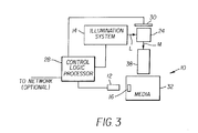
- An illumination system 14 provides an incident light beam L through a polarizing beamsplitter 24 to a spatial light modulator 30.
- Polarizing beamsplitter 24 reflects one polarized component of incident light beam L toward spatial light modulator 30.
- Spatial light modulator 30 modulates individual pixels of the incident light and reflects a modulated light beam M through polarizing beamsplitter 24 to a print lens 38, which focuses modulated light beam M for imaging at image plane 36 onto photosensitive medium 32.
- spatial light modulator 30 is a reflective LCD.
- transmissive LCD spatial light modulator 30 would then be inserted into the light path after illumination system 14, preceded by a polarizer for providing suitably polarized light and followed by an analyzer.
- illumination system 14 provides incident light beam L in a cyclical sequence of red, green, and blue color light. By alternating colors in this way, a single spatial light modulator 30 can be used for successive imaging using red, green, and blue wavelengths, such as is done for photographic film printing, for example.
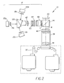
- illumination system 14 uses a dichroic prism 26.
- Figure 2 shows an alternate arrangement in which a Philips prism 126 is used as dichroic prism 26.
- a light source 20 possibly conditioned by an optional polarization filter 18, provides input source light to dichroic prism 26. Illumination from red light source 20r is reflected by a dichroic surface within dichroic prism 26 to emerge as output along optical axis A. Similarly, illumination from blue light source 20b is reflected from a dichroic surface within dichroic prism 26 to emerge as output along optical axis A. Illumination from green light source 20g is transmitted through dichroic prism 26, also output along optical axis A. Thus, the action of dichroic prism 26 combines each of light sources 20r, 20g, 20b to provide output light along optical axis A.
- the X-cube that serves as dichroic prism 26 exhibits sensitivity to the angle of incident light, giving best performance with light at normal or near-normal incidence. For this reason, flat LED arrays are preferred for light source 20, as shown in Figures 1 and 2.
- Optional red, green, and blue polarization filters 18r, 18g, and 18b condition the polarization of light from the corresponding light sources 20r, 20g, and 20b. Condensing lens 42 then optimizes capture of light from the LEDs.
- Additional beam-shaping optics are provided to further condition this output light in order to provide incident light beam L for polarizing beamsplitter 24.
- Output light from dichroic prism 26 goes to a condenser lens 42 and to a field lens 50 which directs the illumination beam to a uniformizer 44, such as an optical tunnel, integrating bar, or lenslet array, that provides a uniform illumination field for incident light beam L.
- a condenser lens 48 then directs uniform incident light beam L to polarizing beamsplitter 24.
- light source 20 and the lenslet array or integrator bar of uniformizer 44 have substantially the same height-width aspect ratio as spatial light modulator 30.
- each light source 20 provides illumination at the same cone angle, maximizing brightness and simplifying the design of uniformizer 44 and lenses 42 and 50.
- a control logic processor 28 typically a dedicated microprocessor or other computer, controls illumination system 14 to adjust the brightness and duration of incident light beam L for each color. Since the exposure energy is proportional to brightness (or intensity) and duration, control of illumination system 14 allows control logic processor to adapt printing apparatus 10 to a number of compatible types of photosensitive media 32. An operator could provide commands to control logic processor to indicate the type of media 32. In the embodiment shown in Figure 3, automatic detection is provided.
- a sensor 12 connects as input to control logic processor 28. Sensor 12 detects the presence of an indicator 16 that is coupled to photosensitive media 32.
- Optional sensor 12 can thus read encoded information from indicator 16, where this information concerns photosensitive medium 32. This information can be used by control logic processor 28 to change the behavior of illumination system 14 appropriately.
- Table 1 lists a representative number of possible sensors 12 and the corresponding indicator 16 provided with photosensitive medium 32.
- Sensor 12 could be: Barcode or other optical encoding Barcode reader or other optical reader, such as built-in or hand-held scanner.
- Transponder containing a memory that includes identifying data for the media, such as an RF transponder, "SAMPT” ( S elective A ddressable M ulti- P age T ransponder), part number “RI-TRP-IR2B” available from Texas Instruments, Incorporated.
- Transceiver such as an RF transceiver, for example, "Model S2000”TM transceiver, available from Texas Instruments, Incorporated, located in Dallas, Texas, USA.
- Magnetically encoded strip Magnetic strip reader Memory device such as an I-button, manufactured by Dallas Semiconductor Corp., Dallas, Texas.
- I-button reader Mechanical configuration, connector, or attachment. Electro-mechanical sensor stimulated or activated by mechanical configuration, connector, or attachment.
- control logic processor 28 would be capable of controlling multiple variables in the exposure process, such as light intensity and duration for illumination system 14 or voltage bias settings for spatial light modulator 30, for example.
- indicator 16 Just a few examples of types of information that can be encoded using indicator 16 include:
- control logic processor 28 could be programmed for automatic access to the network site, using techniques familiar to those skilled in networking technology. This would allow control logic processor 28 to obtain the needed processing parameters or to download executable instructions for processing photosensitive medium 32.
- spatial light modulator 30 forms images in color-sequential fashion in printing apparatus 10 of the present invention.
- spatial light modulator 30 forms the red component of an image frame when provided the data for the red component and illuminated by the red color source, then forms the green component when provided the data for the green component and illuminated by the green color source, and then forms the blue component when provided the data for the blue component and illuminated by the blue component source.
- This pattern repeats: red, green, and blue for each successive frame.
- control logic processor 28 can configure spatial light modulator 30 with a different set of parameters, such as voltage bias level. In this way, spatial light modulator 30 can adjust its behavior for each component color.
- the image data processed by control logic processor 28 can also be conditioned using a separate Look-Up Table (LUT) for each color.
- LUT Look-Up Table
- printing apparatus 10 is able to optimize color printing for each component color.
- component colors are R, G, and B, however, the method and apparatus of the present invention could be readily adapted to an alternate color sequence.
- Light Source 20 Component Selection and Options
- light source 20 is an LED array, fabricated by assembling multiple LEDs on a surface.
- a preferred embodiment uses LEDs such as Model No. NSPB500 and NSPG500 series blue and green devices available from Nichia America Corp., Mountville, PA or H3000L series red devices available from Stanley Electric Co., Ltd, Tokyo, Japan.
- Commercial LED arrays that could be used include types such as the Luxeon Star/O LXHL-NE98, available from LumiLeds Lighting, San Jose, CA. LEDs have a number of advantages for providing imaging light, including high brightness, spectral purity, and fast switching times.
- Alternative light sources include other LED types or lasers. While some types of lamps might be used, such devices would require additional filtering and shutter components, which can add cost and complexity as well as introducing undesirable heat and space requirements.
- light sources 20r, 20g, and 20b would use the same basic type of device. As noted above, this provides the inherent advantages of identical light cones for each color. However, it might be preferred to employ different types of light source devices, in a hybrid arrangement, within the same illumination system 14. As just one example, a laser could be used as part of light source 20r, 20g, or 20b, with LEDs or other sources used for other colors. The selection of a suitable device for light source 20r, 20g, or 20b would be based on factors such as the response characteristics of photosensitive medium 32, device availability and cost, or printing speed requirements, for example.
- light is used for exposure.
- the present invention does not restrict light sources 20 to the visible spectrum.
- One or more light sources 20 could provide radiant energy from infrared or ultraviolet regions, for example.
- FIG 4 an alternate embodiment is shown, in which printing apparatus 10 alternately provides invisible light from optional light source 20i. From the view of Figure 4, infrared or ultraviolet light from light source 20i, conditioned by optional polarization filter 18i, is reflected into the illumination path by dichroic mirror 52. Using the alternate embodiment of Figure 4, fourth light source 20i could be used for imaging onto the same photosensitive medium 32 that accepts red, green, and blue light.
- fourth light source 20i could be used independently from other light sources 20r, 20g, 20b with one or more different types of photosensitive media 32.
- light source 20i providing infrared light might be the best illumination source for exposing some types of black and white or other monochromatic film media.
- printing apparatus 10 could detect a type of photosensitive medium 32 requiring a separate light source instead of, or in addition to, conventional RGB light.
- Photosensitive medium 32 could be an intermediate negative film for motion picture production, such as Eastman EXR Color Intermediate Film EK 5244, manufactured by Eastman Kodak Company, Rochester, New York. Alternately, photosensitive medium 32 could be a print film, such as KODAK VISION Premier Color Print Film / 2393, also manufactured by Eastman Kodak Company, Rochester, New York
- Photosensitive medium 32 can be more broadly interpreted to include any of a number of types of sensitized film, paper, or other surface having photosensitive emulsions that respond to image-bearing light.
- Photosensitive medium 32 could be, for example, a reversal film medium that is positive-acting, so that increasing levels of exposure cause decreasing film densities.
- reversal film media include conventional slide film, such as Kodachrome and Ektachrome slide films manufactured by Eastman Kodak Company, Rochester, NY.
- Photosensitive medium 32 can also include an intermediate surface used for forming a color image such as, for example, an electrophotographic imaging medium.
- Photosensitive medium 32 could alternately comprise an electronic photosensor array or grid employed as a component in an imaging path.
- Photosensitive medium 32 could also be a dry process media type.
- printing apparatus 10 of the present invention could be configured to be adaptable to more than one type of photosensitive medium 32.
- a number of adjustments could be made to components of printing apparatus 10 for providing optimal exposure conditions, such as the following:
- LUTs Look-Up-Tables
- the method of the present invention takes advantage of geometric symmetries of dichroic prism 26 or Philips prism 126 for alignment. Moreover, because light sources 20r, 20g, and 20b can be situated near the surfaces of dichroic prism 26 as shown in Figure 1, or near the surfaces of Philips prism 126 as shown in Figure 2, spacing requirements and tolerance problems are minimized.
- light having any suitable wavelength, including light outside the visible spectrum can be used for any of light sources 20 in illumination source 14. While the description of the embodiment of Figure 4 would generally be best suited for exposure light outside the visible spectrum, optional light source 20i could be visible light at some alternate wavelength that is particularly suited to a class of photosensitive media 32.
Landscapes
- Physics & Mathematics (AREA)
- General Physics & Mathematics (AREA)
- Printers Or Recording Devices Using Electromagnetic And Radiation Means (AREA)
- Projection-Type Copiers In General (AREA)
- Optical Elements Other Than Lenses (AREA)
- Microscoopes, Condenser (AREA)
- Liquid Crystal (AREA)
Applications Claiming Priority (2)
| Application Number | Priority Date | Filing Date | Title |
|---|---|---|---|
| US67929 | 1979-08-20 | ||
| US10/067,929 US6624949B2 (en) | 2002-02-06 | 2002-02-06 | Printing apparatus for photosensitive media using dichroic prism in illumination path |
Publications (1)
| Publication Number | Publication Date |
|---|---|
| EP1335582A1 true EP1335582A1 (de) | 2003-08-13 |
Family
ID=27610522
Family Applications (1)
| Application Number | Title | Priority Date | Filing Date |
|---|---|---|---|
| EP03075251A Withdrawn EP1335582A1 (de) | 2002-02-06 | 2003-01-27 | Printer für lichtempfindliche Medien mit dichroitischem Prisma im Belichtungsstrahlengang |
Country Status (3)
| Country | Link |
|---|---|
| US (1) | US6624949B2 (de) |
| EP (1) | EP1335582A1 (de) |
| JP (1) | JP2003287820A (de) |
Cited By (2)
| Publication number | Priority date | Publication date | Assignee | Title |
|---|---|---|---|---|
| GB2400920A (en) * | 2003-04-24 | 2004-10-27 | Eastman Kodak Co | Printing on media of varying contrast |
| FR2935813A1 (fr) * | 2008-09-11 | 2010-03-12 | Kis | Installation pour l'exposition d'un film cinematographique a partir d'images numeriques |
Families Citing this family (18)
| Publication number | Priority date | Publication date | Assignee | Title |
|---|---|---|---|---|
| US7095430B2 (en) * | 2001-12-27 | 2006-08-22 | Fuji Photo Film Co., Ltd. | Image exposing apparatus and image exposing method |
| US6882356B2 (en) * | 2003-02-11 | 2005-04-19 | Eastman Kodak Company | Method and apparatus for watermarking film |
| US7004602B2 (en) * | 2003-02-25 | 2006-02-28 | Ryan Waters | LED light apparatus and methodology |
| US6969180B2 (en) | 2003-02-25 | 2005-11-29 | Ryan Waters | LED light apparatus and methodology |
| US20050083696A1 (en) * | 2003-10-20 | 2005-04-21 | Po-Liang Chiang | Structure of LED illuminating apparatus |
| US6917758B1 (en) * | 2003-12-19 | 2005-07-12 | Eastman Kodak Company | Method of image compensation for watermarked film |
| US6980226B2 (en) * | 2004-02-13 | 2005-12-27 | Eastman Kodak Company | Watermarking method for motion picture image sequence |
| DE102004038554A1 (de) * | 2004-08-06 | 2006-03-16 | Thomson Broadcast And Media Solutions Gmbh | Filmbelichter und Verfahren zur Belichtung von lichtempfindlichen Filmen |
| US7167314B2 (en) * | 2005-03-17 | 2007-01-23 | Hewlett-Packard Development Company, L.P. | Projector with total cross total internal reflection (TIR) prisms |
| KR100760299B1 (ko) * | 2005-12-06 | 2007-09-19 | 삼성전자주식회사 | 프로젝션 시스템 및 그 제어방법 |
| WO2007100690A2 (en) * | 2006-02-23 | 2007-09-07 | Microvision, Inc. | Scanned beam source and systems using a scanned beam source for producing a wavelength-compensated composite beam of light |
| TWI336160B (en) * | 2006-12-01 | 2011-01-11 | Ind Tech Res Inst | Hybrid power-generating device |
| US8289495B2 (en) * | 2007-01-09 | 2012-10-16 | Thomson Licensing | Film printing system and method utilizing a digital light processing imager or organic light emitting diode |
| US8238029B2 (en) * | 2009-11-13 | 2012-08-07 | Microvision, Inc. | Dichroic filter laser beam combining |
| DE102010046395B4 (de) * | 2010-09-24 | 2013-10-24 | Printprocess Ag | Belichtungsanordnung |
| KR102030240B1 (ko) * | 2017-09-12 | 2019-10-08 | 재단법인 대구경북첨단의료산업진흥재단 | 혈류 측정 장치 |
| US11741633B2 (en) * | 2021-05-17 | 2023-08-29 | Nvidia Corporation | Converting discrete light attenuation into spectral data for rendering object volumes |
| JP7800237B2 (ja) * | 2022-03-18 | 2026-01-16 | セイコーエプソン株式会社 | 投写装置 |
Citations (7)
| Publication number | Priority date | Publication date | Assignee | Title |
|---|---|---|---|---|
| US5327263A (en) * | 1989-12-18 | 1994-07-05 | Sharp Kabushiki Kaisha | Image processing apparatus employing a spatial light modulator |
| EP0679036A2 (de) * | 1994-04-21 | 1995-10-25 | Seiko Instruments Inc. | Bildausgabeanlage |
| US5580142A (en) * | 1992-05-06 | 1996-12-03 | Canon Kabushiki Kaisha | Image forming apparatus and projector using the same |
| US5982407A (en) * | 1995-12-13 | 1999-11-09 | Fuji Photo Film Co., Ltd. | Color printer |
| WO2000038432A2 (en) * | 1998-12-22 | 2000-06-29 | Varintelligent (Bvi) Limited | Optical assembly for reflective light valves |
| EP1235421A2 (de) * | 2001-02-27 | 2002-08-28 | Eastman Kodak Company | Verfahren und Vorrichtung zum Drucken von Bildern mit hoher Auflösung mit vielfach reflektierenden räumlichen Lichtmodulatoren |
| EP1291711A1 (de) * | 2001-09-05 | 2003-03-12 | Eastman Kodak Company | Printer für lichtempfindliche Medien mit einer hybriden Lichtquelle |
Family Cites Families (22)
| Publication number | Priority date | Publication date | Assignee | Title |
|---|---|---|---|---|
| US5808410A (en) * | 1992-07-28 | 1998-09-15 | Philips Electronics North America Corporation | Flat panel light source for liquid crystal displays |
| US5433859A (en) | 1993-07-12 | 1995-07-18 | Pall Corporation | Supported microporous filtration membrane and method of using same |
| JPH07140587A (ja) * | 1993-11-12 | 1995-06-02 | Canon Inc | 乾式銀塩感光体、及び同感光体を用いる画像形成方法 |
| US5795047A (en) | 1994-12-09 | 1998-08-18 | Matsushita Electric Industrial Co., Ltd. | Projection lens and projection display apparatus |
| US5978008A (en) * | 1995-11-22 | 1999-11-02 | Polaroid Corporation | Automatic color correction for a white-light printer |
| US5917560A (en) | 1995-11-28 | 1999-06-29 | Raytheon Company | Low cost color cube for liquid crystal light valve projector |
| US5605390A (en) | 1996-01-25 | 1997-02-25 | Sarif, Inc. | Optical projector |
| US5684620A (en) * | 1996-01-30 | 1997-11-04 | Schoonscan, Inc. | High resolution imaging system and method of imaging using the same |
| US6053615A (en) | 1996-08-02 | 2000-04-25 | In Focus Systems, Inc. | Image projector with polarization conversion system |
| WO1998008118A1 (fr) * | 1996-08-20 | 1998-02-26 | Seiko Epson Corporation | Dispositif optique, appareil d'eclairage a lumiere polarisee et affichage du type a projection |
| US6229651B1 (en) | 1996-11-01 | 2001-05-08 | Balzers Aktienresellschaft | Optical element and its manufacturing process |
| JPH10142702A (ja) * | 1996-11-05 | 1998-05-29 | Brother Ind Ltd | 画像形成装置 |
| JP3769895B2 (ja) | 1997-09-26 | 2006-04-26 | コニカミノルタフォトイメージング株式会社 | 画像形成装置 |
| KR19990074812A (ko) * | 1998-03-14 | 1999-10-05 | 윤종용 | 호환형 광픽업장치 |
| US6019474A (en) | 1998-10-06 | 2000-02-01 | International Business Machines Corporation | Modified X-cube arrangement for improved contrast projection display |
| US6220713B1 (en) | 1998-10-23 | 2001-04-24 | Compaq Computer Corporation | Projection lens and system |
| US6215547B1 (en) | 1998-11-19 | 2001-04-10 | Eastman Kodak Company | Reflective liquid crystal modulator based printing system |
| US6238051B1 (en) | 1999-01-28 | 2001-05-29 | Duke University | Producing colored light beams from white light |
| US6254237B1 (en) | 1999-04-30 | 2001-07-03 | David K. Booth | Multi-pixel microlens illumination in electronic display projector |
| KR100299974B1 (ko) * | 1999-07-08 | 2001-11-01 | 윤종용 | 화상형성장치의 전전사시스템 |
| US6262851B1 (en) | 2000-01-18 | 2001-07-17 | Hewlett-Packard Co. | Double-pass projection displays with separate polarizers and analyzers |
| JP2003021800A (ja) * | 2001-07-10 | 2003-01-24 | Canon Inc | 投射型表示装置 |
-
2002
- 2002-02-06 US US10/067,929 patent/US6624949B2/en not_active Expired - Fee Related
-
2003
- 2003-01-15 JP JP2003006712A patent/JP2003287820A/ja active Pending
- 2003-01-27 EP EP03075251A patent/EP1335582A1/de not_active Withdrawn
Patent Citations (7)
| Publication number | Priority date | Publication date | Assignee | Title |
|---|---|---|---|---|
| US5327263A (en) * | 1989-12-18 | 1994-07-05 | Sharp Kabushiki Kaisha | Image processing apparatus employing a spatial light modulator |
| US5580142A (en) * | 1992-05-06 | 1996-12-03 | Canon Kabushiki Kaisha | Image forming apparatus and projector using the same |
| EP0679036A2 (de) * | 1994-04-21 | 1995-10-25 | Seiko Instruments Inc. | Bildausgabeanlage |
| US5982407A (en) * | 1995-12-13 | 1999-11-09 | Fuji Photo Film Co., Ltd. | Color printer |
| WO2000038432A2 (en) * | 1998-12-22 | 2000-06-29 | Varintelligent (Bvi) Limited | Optical assembly for reflective light valves |
| EP1235421A2 (de) * | 2001-02-27 | 2002-08-28 | Eastman Kodak Company | Verfahren und Vorrichtung zum Drucken von Bildern mit hoher Auflösung mit vielfach reflektierenden räumlichen Lichtmodulatoren |
| EP1291711A1 (de) * | 2001-09-05 | 2003-03-12 | Eastman Kodak Company | Printer für lichtempfindliche Medien mit einer hybriden Lichtquelle |
Cited By (4)
| Publication number | Priority date | Publication date | Assignee | Title |
|---|---|---|---|---|
| GB2400920A (en) * | 2003-04-24 | 2004-10-27 | Eastman Kodak Co | Printing on media of varying contrast |
| FR2935813A1 (fr) * | 2008-09-11 | 2010-03-12 | Kis | Installation pour l'exposition d'un film cinematographique a partir d'images numeriques |
| EP2164241A1 (de) * | 2008-09-11 | 2010-03-17 | Photo ME Holding France | Anlage zum Vorführen eines Kinofilms auf der Grundlage von Digitalbildern |
| US8039825B2 (en) | 2008-09-11 | 2011-10-18 | Photo Me Holding France | Installation for exposing a cinematographic film from digital images |
Also Published As
| Publication number | Publication date |
|---|---|
| JP2003287820A (ja) | 2003-10-10 |
| US6624949B2 (en) | 2003-09-23 |
| US20030147144A1 (en) | 2003-08-07 |
Similar Documents
| Publication | Publication Date | Title |
|---|---|---|
| US6624949B2 (en) | Printing apparatus for photosensitive media using dichroic prism in illumination path | |
| EP1291711B1 (de) | Printer für lichtempfindliche Medien mit einer hybriden Lichtquelle | |
| US6762785B2 (en) | Four color film writer | |
| US6580490B1 (en) | Method and apparatus for printing images in multiple formats using a spatial light modulator | |
| EP1285769B1 (de) | Verfahren und Vorrichtung zum Drucken von Bildern mit hoher Auflösung mit vielfach reflektierenden räumlichen Lichtmodulatoren | |
| EP1177908B1 (de) | Verfahren und Gerät zum monochromatischen Drucken unter Verwendung eines räumlichen Lichtmodulators | |
| EP1235421A2 (de) | Verfahren und Vorrichtung zum Drucken von Bildern mit hoher Auflösung mit vielfach reflektierenden räumlichen Lichtmodulatoren | |
| US7145520B2 (en) | Display apparatus box using a spatial light modulator | |
| US6980280B2 (en) | Two level image writer | |
| US6480259B1 (en) | Method and apparatus for printing monochromatic images using a spatial light modulator having a selectable light source | |
| US6751005B1 (en) | Compensating for pixel defects by spatial translation of scene content | |
| EP1291702A1 (de) | Drucken von Rasterbildern entsprechender Bewegtbilder | |
| US7023463B2 (en) | Method and apparatus for printing images from digital image data | |
| US20070153080A1 (en) | High-speed continuous film writer | |
| US7164434B2 (en) | LCD based imaging apparatus for printing multiple formats | |
| US20040201864A1 (en) | Digital/optical hybrid printer utilizing reflective spatial light modulation technology | |
| JP2002244056A (ja) | 露光装置およびこれを備えた写真処理装置 | |
| JPH111017A (ja) | 画像形成装置 | |
| JP2003094730A (ja) | プリンタ装置 | |
| JP2001330892A (ja) | プリントヘッドおよびこれを備えた写真処理装置 | |
| JPH08248525A (ja) | 写真プリンタ | |
| JP2000194081A (ja) | 露光装置、露光方法および記録装置 | |
| JP2002090918A (ja) | 露光装置 | |
| JP2005250367A (ja) | 画像形成装置及び写真感光材料 |
Legal Events
| Date | Code | Title | Description |
|---|---|---|---|
| PUAI | Public reference made under article 153(3) epc to a published international application that has entered the european phase |
Free format text: ORIGINAL CODE: 0009012 |
|
| AK | Designated contracting states |
Designated state(s): AT BE BG CH CY CZ DE DK EE ES FI FR GB GR HU IE IT LI LU MC NL PT SE SI SK TR |
|
| AX | Request for extension of the european patent |
Extension state: AL LT LV MK RO |
|
| 17P | Request for examination filed |
Effective date: 20040117 |
|
| AKX | Designation fees paid |
Designated state(s): DE GB |
|
| STAA | Information on the status of an ep patent application or granted ep patent |
Free format text: STATUS: THE APPLICATION IS DEEMED TO BE WITHDRAWN |
|
| 18D | Application deemed to be withdrawn |
Effective date: 20070801 |