EP1336330A1 - Semoir - Google Patents
Semoir Download PDFInfo
- Publication number
- EP1336330A1 EP1336330A1 EP03360021A EP03360021A EP1336330A1 EP 1336330 A1 EP1336330 A1 EP 1336330A1 EP 03360021 A EP03360021 A EP 03360021A EP 03360021 A EP03360021 A EP 03360021A EP 1336330 A1 EP1336330 A1 EP 1336330A1
- Authority
- EP
- European Patent Office
- Prior art keywords
- seeder according
- cylinder
- articulation
- linked
- central roller
- Prior art date
- Legal status (The legal status is an assumption and is not a legal conclusion. Google has not performed a legal analysis and makes no representation as to the accuracy of the status listed.)
- Granted
Links
- 238000009331 sowing Methods 0.000 title claims description 8
- 230000000284 resting effect Effects 0.000 claims 1
- 238000010899 nucleation Methods 0.000 abstract 1
- 239000002689 soil Substances 0.000 description 15
- 210000000056 organ Anatomy 0.000 description 7
- 238000002513 implantation Methods 0.000 description 4
- 241000946381 Timon Species 0.000 description 2
- 230000000694 effects Effects 0.000 description 2
- 238000000034 method Methods 0.000 description 2
- 208000031968 Cadaver Diseases 0.000 description 1
- 238000012550 audit Methods 0.000 description 1
- 238000005056 compaction Methods 0.000 description 1
- 238000007596 consolidation process Methods 0.000 description 1
- 230000008878 coupling Effects 0.000 description 1
- 238000010168 coupling process Methods 0.000 description 1
- 238000005859 coupling reaction Methods 0.000 description 1
- 230000001788 irregular Effects 0.000 description 1
- 238000012986 modification Methods 0.000 description 1
- 230000004048 modification Effects 0.000 description 1
- 238000012856 packing Methods 0.000 description 1
- 238000006467 substitution reaction Methods 0.000 description 1
Images




Classifications
-
- A—HUMAN NECESSITIES
- A01—AGRICULTURE; FORESTRY; ANIMAL HUSBANDRY; HUNTING; TRAPPING; FISHING
- A01B—SOIL WORKING IN AGRICULTURE OR FORESTRY; PARTS, DETAILS, OR ACCESSORIES OF AGRICULTURAL MACHINES OR IMPLEMENTS, IN GENERAL
- A01B49/00—Combined machines
- A01B49/04—Combinations of soil-working tools with non-soil-working tools, e.g. planting tools
- A01B49/06—Combinations of soil-working tools with non-soil-working tools, e.g. planting tools for sowing or fertilising
-
- A—HUMAN NECESSITIES
- A01—AGRICULTURE; FORESTRY; ANIMAL HUSBANDRY; HUNTING; TRAPPING; FISHING
- A01C—PLANTING; SOWING; FERTILISING
- A01C7/00—Sowing
- A01C7/20—Parts of seeders for conducting and depositing seed
- A01C7/201—Mounting of the seeding tools
- A01C7/205—Mounting of the seeding tools comprising pressure regulation means
Definitions
- Such an agricultural machine is known to those skilled in the art. Indeed, the company Kuhn SA manufactures and markets such a seed drill, the "Fastliner 1000 Series".
- This machine comprises on the one hand, a drawbar and a front chassis supported by wheels.
- Said front chassis also carries opening tools.
- Said machine comprises, on the other hand, a rear chassis linked to said front chassis by means of a central articulation.
- Said rear chassis carries sowing elements.
- Said rear chassis also includes consolidation rollers located in front of said sowing elements and behind said wheels supporting the front chassis. Said rollers are arranged over the entire working width of said seed drill in order to press the soil.
- Said rollers combined with the support wheels of the front chassis contribute to the preparation of an optimal seed bed thanks to a crumbling and packing effect of the seed bed.
- the wheels of the device are therefore useful in the transport configuration as in the working configuration.
- the object of the present invention is to remedy this drawback of the state of the technique.
- the seed drill according to the present invention is characterized by the fact that said seed drill has a central roller for accompanying said wheels during maneuvers.
- the pressure exerted by said wheels of the device on the soil is reduced and consequently the reconsolidation of the seedbed at the end of field is less important.
- said central roller can be released from its working position by pivoting around at least one articulation.
- the pressure exerted on the ground by said central roller is advantageously adjustable by means of minus a cylinder.
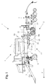
- Figure 1 shows, in side view, a drill (1) according to this invention.
- said seed drill (1) is moved in a direction and a direction of advance indicated by the arrow (F).
- the following concepts "front” and “rear”, “front” and “behind” are defined with respect to the direction of advance (F) and the concepts “right” and “left” are defined by looking at said seed drill (1) from the rear in the direction of advance (F).
- said seed drill (1) comprises a body (2) linked to the rear of a tractor (not shown) by means of a drawbar coupling (3).
- said body (2) comprises a sowing device (4) carried by a chassis.
- said sowing device (4) consists in particular of a hopper (5) linked to a front frame (6), and of organs for planting seeds in the ground (7) supported by a rear frame (8).
- Said seed drill (1) shown in the figures allows, in a way particularly advantageous, to prepare and seed a strip of land on unworked soil or on previously worked soil.
- Said front chassis (6) of the seed drill (1) therefore carries tools (9) preparing the seedbed.
- said front frame (6) When the seed drill (1) is used on a soil without any preparation, it is advantageous to provide said front frame (6) with opening discs arranged in front of said planting members (7) in order to work the soil on a strip narrow. Said opening discs are arranged along at least one line substantially horizontal and perpendicular to said direction of advance (F). Through elsewhere, said opening discs are distributed at least substantially uniform over the entire working width of said seed drill (1). By cons on a floor dethatched, it will be advisable to provide the front chassis (6) with a row of blades graders and a row of high ripple discs for leveling and fill the soil over the entire width of the seed drill (1).
- said front chassis (6) rests at least partially on the ground by means of two wheels (10).
- said wheels (10) are linked to said front chassis (6), advantageously so as to be able to be moved in height, by means of connecting members (11).
- said wheels (10) are used for work and transport and rotate around an axis of rotation substantially horizontal and orthogonal to the direction of advance (F).
- said connecting members (11) consist in particular of a carrying carriage (12) linked to said front chassis (6) at means of at least one second articulation (13) of axis at least substantially horizontal and orthogonal to said direction of advance (F).
- Said front chassis (6) advantageously comprises two second joints (13) arranged on the side and on the other side of the central axis of said seed drill (1).
- Said carrying carriage (12) is pivoted around said second articulations (13) by means of two lifting cylinders (14).
- said wheels (10) can be moved away from or closer to said front frame (6).
- Said seed drill (1) can thus be lowered for work or raised For transport.
- said seed drill (1) comprises also an adjustment device defining the maximum lowering of said seed drill (1). The working depth of said tools (9) can therefore easily be adjusted.
- the front of said rear chassis (8) is linked to the rear of said front chassis (6) by means of a central articulation (15) with at least substantially vertical axis.
- Said articulation central (15) is advantageously included in a median vertical plane of said front frame (6).
- said central articulation (15) is also arranged substantially midway between said tools (9) and said organs for planting seeds in the ground (7). So when said seed drill (1) makes a turn or bypasses an obstacle, said central articulation (15) allows each seed planting organ in the soil (7) to stay well in the groove created by the corresponding tool (9).
- said seed drill (1) comprises press rollers combined with wheels (10) in order to press the soil over the entire working width.
- the said press rolls are preferably arranged between the tools (9) and the members planting seeds in the soil (7).
- rollers end (16) are arranged on either side of said wheels (10) and are intended to compact the earth to the right and to the left of said wheels (10).
- Said rollers end (16) are advantageously linked to said rear frame (8).
- the pressure of reconsolidation on the ground of said end rollers (16) is advantageously adjustable. It is also possible to completely separate said end rollers (16) from their working position.
- said seed drill (1) comprises a central roller (17) accompanying the wheels (10) during maneuvers.
- the remaining working width between said wheels (10) is, for its hand, tamp down by said central roller (17).
- said carriage carrier (12) is pivoted around said second articulations (13) by means said lifting cylinders (14) and said wheels (10) move away from the front chassis (6).
- the seed drill (1) is in its raised position and said tools (9), said end rollers (16) as well as the implantation members (7) are no longer in contact with the ground.
- This configuration is ideal for making a U-turn in good conditions.
- the central roller (17) remains pressed on the ground to accompany said wheels (10) to perform the maneuver.
- the combination of the wheels (10) and the central roller (17) thus makes it possible to reduce considerably compacting the seedbed at the headland and obtaining a more homogeneous seedbed. Note that soil compaction is only necessary for previously worked land.
- the width (L) of said central roller (17) is substantially equal to the entrepneu (e) of the wheels (10).
- the central roller (17) is located substantially behind the axis of rotation of said wheels (10).
- Said central roller (17) associated with said end rollers (16) constitute said (at least one of said) press roll (s).
- the central roller (17) advantageously completes said (at least one of said) press roll (s), thus the seedbed is ideally packed over the entire working width of the seed drill (1).
- Said central roller (17) is connected to said front frame (6) by means of arms (18).
- said central roller (17) advantageously comprises two arms (18) arranged on either side of said central roller (17).
- Each arm (18) is linked on the one hand, to said central roller (17) by means of a third articulation (19) with an axis substantially parallel to the axis of rotation of said central roller (17).
- each arm (18) is also connected to said carrying carriage (12) and more specifically to the axle (20) of said wheels (10) at means of at least a first articulation (21) with an axis at least substantially horizontal and orthogonal to the direction of advance (F).
- the axis of said (at least one of said first articulation (s) (21) is advantageously parallel to the axis said second joints (13).
- each arm (18) is still linked to the front chassis (6) by means of a jack (22).
- Each cylinder (22) comprises a body (23) linked to said front frame (6) by means of a fifth articulation (24) with at least axis substantially horizontal and orthogonal to the direction of advance (F).
- the axis of this fifth articulation (24) is advantageously parallel to the axis of said second joints (13).
- Each cylinder (22) also includes a piston (25) linked to said respective arm (18) by means of a fourth articulation (26) of axis at least substantially horizontal and orthogonal to the direction of advance (F).
- the axis of this fifth articulation (26) is advantageously parallel to the axis of said second joints (13).
- the axes of said first joints (21), second joints (13), fourth joints (26) and fifth joints (24) substantially form a parallelogram when said central roller (17) is in contact with the ground.
- the ground pressure of the roller can be adjusted central (17) and even release it from its working position.
- the cylinders (22) are placed on either side of said central roller (17).
- said cylinders (22) are double-acting cylinders.
- each length specific of the jack (22) corresponds to a pressure of said central roller (17) exerted on the ground.
- Said cylinder (22) advantageously benefits from an order hydraulic separate from the control of said end rollers (16).
- Said jacks (22) also make it possible to disengage said central roller (17) from his working position. So when the pistons (25) are fully retracted into said bodies (23), the arms (18) supporting said central roller (17) pivot towards the high around said first joints (21).
- Said central roller (17) is is, therefore, in its transport position as visible in the figure 2. It is appreciable to be able to disengage said central roller (17) in its position when, for example, said seed drill (1) is used on non-soil worked which does not therefore require settlement of the seedbed.
- FIGs 6 to 9 show a second embodiment of a drill (1A) according to the present invention.
- This seed drill (1A) has a number of elements which have been described previously. These elements will keep by therefore the same reference number and will not be rewritten.
- Said seed drill (1A) also has a number of elements which are comparable to elements of the drill (1) described above. These elements will be affected by same reference number as these comparable elements of the seed drill (1) followed by the letter A. They will only be described if necessary.
- the seed drill (1A) according to this second embodiment is generally similar to the seed drill (1) shown in Figure 1. The only differences are that each cylinder (22A) is connected to a respective fifth articulation (24A), which is linked said carrier carriage (12). In addition, each cylinder (22A) is combined with a link elastic.
- said arms (18) are connected to said carrier carriage (12) by means of jacks (22A).
- the body (23A) of each cylinder (22A) is connected to said carrier carriage (12) by means of a fifth respective joint (24A) with an axis at least substantially horizontal and orthogonal to the direction of advance (F).
- the piston (25A) of each cylinder (22A) is, meanwhile, connected to said arm (18) by means of a fourth articulation corresponding (26A).
- Said jacks (22A) allow on the one hand, the passage of said central roller (17) from a working position to a transport position.
- each press of the accumulator (27A) corresponds to a length specific to the jack (22A) and therefore to a pressure on the ground of said central roller (17). This elastic connection makes it possible to absorb the relative movement of said roller central (17) relative to said front chassis (6).
- FIG 10 shows a third embodiment of a seed drill (1B) according to the present invention.
- This seed drill (1B) has a number of elements which have been described previously. These elements will keep by therefore the same reference number and will not be rewritten.
- Said seed drill (1B) also has a number of elements which are comparable to elements of the drill (1; 1A) described above. These elements will assigned the same reference number as these comparable planter elements (1) followed by the letter B. They will only be described if necessary.
- the seed drill (1B) according to this third embodiment is on the whole similar to the seed drill (1) shown in Figure 1. The only differences are that that the folding of said central roller (17) for transporting and adjusting the ground pressure are achieved by two independent cylinders.
- each cylinder (22) of the seed drill (1) is replaced by a pair of independent cylinders (22B).
- a first cylinder (28B) allowing only the folding of said roller central (17) for transport, this cylinder (28B) is preferably a double cylinder effect.
- Said first cylinder (28B) comprises a body (29B) linked to said front chassis (6) by means of a fifth articulation (24B) and a piston (30B) linked to the body (31B) of a second cylinder (32B) by a sixth articulation (33B).
- said sixth articulation (33B) is, for its part, linked to said carrier carriage (12) at by means of a connecting rod (34B).
- Said connecting rod (34B) is linked to said carrier carriage (12) at by means of a seventh articulation (35B).
- Said second cylinder (32B) comprises a piston (35B) linked to said arm (18) by means of a fourth articulation (26B).
- Said second cylinder (32B) allows, for its part, the adjustment of the pressure on the ground.
- Said second cylinder (32B) is preferably of the single-acting type, one of which chamber is connected to a pressure accumulator (27B), but said second cylinder (32B) could also be a double-acting type cylinder. Note that each accumulator pressure (27B) corresponds to a specific length of the cylinder (32B) and therefore at a pressure on the ground of said central roller (17).
- FIG 11 shows a fourth embodiment of a seed drill (1C) according to the present invention.
- This seed drill (1C) has a number of elements which have been described previously. These elements will keep by therefore the same reference number and will not be rewritten.
- Said seed drill (1C) also has a number of elements that are comparable to elements of the drill (1; 1A; 1B) described above. These elements will assigned the same reference number as these comparable planter elements (1) followed by the letter C. They will only be described if necessary.
- the seed drill (1C) according to this fourth embodiment is on the whole similar to the seed drill (1B) shown in Figure 10. The only difference is that the pair of cylinders (22B) is replaced by a double cylinder (22C).
- each pair of cylinders (22B) of the seed drill (1B) is replaced by a double cylinder (22C).
- Said cylinder double (22C) consists of a common body (23C), a first piston (30C) and a second piston (35C).
- Said first piston (30C) and said body (23C) constitutes a first cylinder (28C).
- Said first piston (30C) is linked to the fifth articulation (24C) and allows the folding of the central roller (17) for transport.
- Said second piston (35C) and said body (23C) constitutes a second cylinder (32C).
- Said second piston (35C) is connected to said arm (18) by means of a fourth joint (26C).
- Said second piston (31C) allows, for its part, the adjustment of the pressure exerted by said central roller (17) on the ground.
- Folding said central roller (17) for transport is advantageously carried out by said first cylinder (28C) which is of the double-acting cylinder type.
- said second cylinder (32C) which can be of the type single-acting cylinder or double-acting cylinder, one chamber of which is connected to a pressure accumulator (27C).
- said double cylinder (22C) is constituted by two independent cylinders (28C, 32C) of which the body of the first cylinder (28C) is linked rigidly to the body of the second cylinder (32C) so as to form a single body (23C).
- central roller (17) is located substantially in front of the axis of rotation of said wheels (10).
Landscapes
- Life Sciences & Earth Sciences (AREA)
- Soil Sciences (AREA)
- Environmental Sciences (AREA)
- Engineering & Computer Science (AREA)
- Mechanical Engineering (AREA)
- Sowing (AREA)
- Fertilizing (AREA)
- Pharmaceuticals Containing Other Organic And Inorganic Compounds (AREA)
- Drilling Tools (AREA)
- Steroid Compounds (AREA)
- Mechanical Treatment Of Semiconductor (AREA)
- Valve-Gear Or Valve Arrangements (AREA)
- Soil Working Implements (AREA)
Abstract
Description
- un timon d'attelage destiné à être lié à un tracteur,
- un corps comportant
- un châssis composé :
- d'un châssis avant lié audit timon d'attelage s'appuyant sur le sol au moyen de roues qui y sont liées au moyen d'organes de liaison de manière à pouvoir être déplacées en hauteur, et
- d'un châssis arrière lié au châssis avant au moyen d'une articulation centrale d'axe longitudinal au moins sensiblement vertical, ledit châssis arrière porte au moins un rouleau de rappui,
- un dispositif de semis comportant entre autres une trémie et des organes d'implantation de graines dans le sol, lesdits organes d'implantation étant portés par le châssis arrière.
- un châssis composé :
- la figure 1 représente, selon une première forme de réalisation une vue de profil globale d'un semoir conforme à l'invention s'étendant dans une position qui correspond à la position de travail,
- la figure 2 représente le semoir de la figure 1 vu de profil, s'étendant dans une position qui correspond à la position transport,
- la figure 3 représente le semoir de la figure 1 vu de profil, s'étendant dans une position qui correspond à la position de bout de champ lors de manoeuvres,
- la figure 4 représente une vue de dessus du semoir de la figure 1,
- la figure 5 représente un agrandissement selon la figure 3 de la partie au voisinage des roues du semoir,
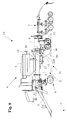
- la figure 6 représente selon une deuxième forme de réalisation vue de profil, un semoir selon l'invention s'étendant dans une position qui correspond à la position de travail,
- la figure 7 représente le semoir de la figure 6 vu de profil, s'étendant dans une position qui correspond à la position transport,
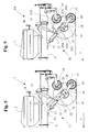
- la figure 8 représente le semoir de la figure 6 vu de profil, s'étendant dans une position qui correspond à la position de bout de champ lors de manoeuvres,
- la figure 9 représente un agrandissement selon la figure 8 de la partie au voisinage des roues du semoir,
- la figure 10 représente selon une troisième forme de réalisation et à une autre échelle la partie au voisinage des roues du semoir,
- la figure 11 représente selon une quatrième forme de réalisation et à une autre échelle la partie au voisinage des roues du semoir.
Claims (29)
- Semoir (1 ; 1A ; 1B ; 1C) comportantcaractérisé par le fait que ledit semoir (1) comporte un rouleau central (17) permettant d'accompagner lesdites roues (10) lors de manoeuvres.un timon d'attelage (3) destiné à être lié à un tracteur,un corps (2) comportantun châssis composé :etd'un châssis avant (6) lié audit timon d'attelage (3) et s'appuyant sur le sol au moyen de roues (10) qui y sont liées au moyen d'organes de liaison (11) de manière à pouvoir être déplacées en hauteur, etd'un châssis arrière (8) lié audit châssis avant (6) au moyen d'une articulation centrale (15) d'axe au moins sensiblement vertical, ledit châssis arrière (8) porte au moins un rouleau de rappui,un dispositif de semis (4) comportant entre autres une trémie (5) et des organes d'implantation de graines dans le sol (7), lesdits organes d'implantation de graines dans le sol (7) étant portés par le châssis arrière (8),
- Semoir selon la revendication 1, caractérisé par le fait que ledit rouleau central (17) complète ledit(desdits) rouleau(x) de rappui.
- Semoir selon la revendication 1 ou 2, caractérisé par le fait que ledit rouleau central (17) est situé sensiblement derrière l'axe de rotation desdites roues (10).
- Semoir selon l'une quelconque des revendications 1 à 3, caractérisé par le fait que la largeur dudit rouleau central (17) est sensiblement égale à l'entrepneu (e) desdites roues (10).
- Semoir selon l'une quelconque des revendications 1 à 4, caractérisé par le fait que ledit rouleau central (17) est dégagé de sa position de travail en pivotant autour d'au moins une première articulation (21).
- Semoir selon l'une quelconque des revendications 1 à 5, caractérisé par le fait que ledit rouleau central (17) est lié à un chariot porteur (12) au moyen d'au moins un bras (18) et que ledit chariot porteur (12) est lié audit châssis avant (6) au moyen d'au moins une deuxième articulation (13).
- Semoir selon la revendication 6 prise en combinaison avec la revendication 5, caractérisé par le fait que ledit (au moins un desdits) bras (18) est(sont) lié(s) d'une part audit rouleau central (17) au moyen d'au moins une troisième articulation (19) et d'autre part audit chariot porteur (12) au moyen de ladite (au moins une desdites) première(s) articulation(s) (21).
- Semoir selon la revendication 6 ou 7, caractérisé par le fait qu 'au moins un vérin (22 ; 22B ; 22C) est implanté entre ledit (au moins un desdits) bras (18) et ledit châssis avant (6).
- Semoir selon la revendication 8, caractérisé par le fait que ledit (au moins un desdits) vérin(s) (22; 22B; 22C) est(sont) lié(s) audit (à au moins un desdits) bras (18) au moyen d'au moins une quatrième articulation (26 ; 26B ; 26C).
- Semoir selon la revendication 8 ou 9, caractérisé par le fait que la pression exercée par ledit rouleau central (17) sur le sol est réglable au moyen des vérins (22 ; 22B ; 22C).
- Semoir selon l'une quelconque des revendications 8 à 10, caractérisé par le fait que ledit (au moins un desdits) vérin(s) (22 ; 22B ; 22C) est(sont) lié(s) audit châssis avant (6) au moyen d'au moins une cinquième articulation (24 ; 24B ; 24C).
- Semoir selon la revendication 11, caractérisé par le fait que ledit (au moins un desdits) vérin(s) (22) est un vérin double effet.
- Semoir selon la revendication 11, caractérisé par le fait que ledit (au moins un desdits) vérin(s) (22C) est un vérin double constitué d'un corps (23C), d'un premier piston (30C) et d'un deuxième piston (35C).
- Semoir selon la revendication 13, caractérisé par le fait que ledit premier piston (30C) et ledit corps (23C) constitue un premier vérin (28C), ledit premier vérin (28C) est un vérin double effet.
- Semoir selon la revendication 13 ou 14, caractérisé par le fait que ledit deuxième piston (35C) et ledit corps (23C) constitue un deuxième vérin (32C).
- Semoir selon la revendication 15, caractérisé par le fait que ledit deuxième vérin (32C) est associé à un accumulateur de pression (27C).
- Semoir selon la revendication 15 ou 16, caractérisé par le fait que ledit deuxième vérin (32C) est lié audit bras (18).
- Semoir selon l'une quelconque des revendications 13 à 17, caractérisé par le fait que lesdits deux vérins indépendants (28C, 32C) sont liés l'un à l'autre de façon rigide par ledit corps (23C), lesdits deux vérins indépendants (28C, 32C) forment ledit vérin double.
- Semoir selon la revendication 11, caractérisé par le fait que ledit(au moins un desdits) vérin(s) (22B) est constitué par deux vérins indépendants (28B, 32B) liés l'un à l'autre au moyen d'une sixième articulation (33B).
- Semoir selon la revendication 19, caractérisé par le fait que ladite sixième articulation (33B) est liée audit chariot porteur (12) au moyen d'une bielle (34B), ladite bielle (34B) est liée audit chariot porteur (12) au moyen d'une septième articulation (35B).
- Semoir selon la revendication 19, caractérisé par le fait que ledit premier vérin indépendant (28B) est un vérin double effet.
- Semoir selon la revendication 19, caractérisé par le fait que ledit deuxième vérin (32B) est associé à un accumulateur de pression (27C).
- Semoir selon la revendication 22, caractérisé par le fait que ledit vérin deuxième (32B) est lié audit bras (18).
- Semoir selon la revendication 6 ou 7, caractérisé par le fait qu' au moins un vérin (22A) est implanté entre ledit (au moins un desdits) bras (18) et ledit chariot porteur (12).
- Semoir selon la revendication 24, caractérisé par le fait que ledit (au moins un desdits) vérin(s) (22A) est(sont) lié(s) audit chariot porteur (12) au moyen d'au moins une cinquième articulation (24A).
- Semoir selon la revendication 24 ou 25, caractérisé par le fait que ledit (au moins un desdits) vérin(s) (22A) est(sont) lié(s) audit (à au moins un desdits) bras (18) au moyen d'au moins une quatrième articulation (26A).
- Semoir selon l'une quelconque des revendications 25 à 26, caractérisé par le fait que la pression exercée par ledit rouleau central (17) sur le sol est réglable au moyen des vérins (22A).
- Semoir selon l'une quelconque des revendications 24 à 27, caractérisé par le fait que ledit (au moins un desdits) vérin(s) (22A) est(sont) du type vérin à double effet.
- Semoir selon la revendication 28, caractérisé par le fait que ledit (au moins un desdits) vérin(s) (22A) est(sont) associé(s) à un accumulateur de pression (27A).
Applications Claiming Priority (2)
| Application Number | Priority Date | Filing Date | Title |
|---|---|---|---|
| FR0201856A FR2835691B1 (fr) | 2002-02-14 | 2002-02-14 | Semoir |
| FR0201856 | 2002-02-14 |
Publications (2)
| Publication Number | Publication Date |
|---|---|
| EP1336330A1 true EP1336330A1 (fr) | 2003-08-20 |
| EP1336330B1 EP1336330B1 (fr) | 2007-06-06 |
Family
ID=27620219
Family Applications (1)
| Application Number | Title | Priority Date | Filing Date |
|---|---|---|---|
| EP03360021A Expired - Lifetime EP1336330B1 (fr) | 2002-02-14 | 2003-02-06 | Semoir |
Country Status (5)
| Country | Link |
|---|---|
| EP (1) | EP1336330B1 (fr) |
| AT (1) | ATE363823T1 (fr) |
| DE (1) | DE60314193T2 (fr) |
| DK (1) | DK1336330T3 (fr) |
| FR (1) | FR2835691B1 (fr) |
Cited By (4)
| Publication number | Priority date | Publication date | Assignee | Title |
|---|---|---|---|---|
| EP1782668A1 (fr) * | 2005-11-03 | 2007-05-09 | Amazonen-Werke H. Dreyer GmbH & Co. KG | Remorque pour outil agricole de travail du sol |
| EP2363013A1 (fr) * | 2010-03-02 | 2011-09-07 | Lemken GmbH & Co. KG | Combiné de semis doté d'un dispositif pour maintenir une valeur limite de glissement |
| EP2534933A1 (fr) * | 2011-06-17 | 2012-12-19 | Kuhn S.A. | Semoir avec des éléments de rappui constituant les roues de transport |
| EP3530094A1 (fr) * | 2018-02-26 | 2019-08-28 | Kuhn S.A. | Module de semis pour machine agricole combinée et machine agricole combinée comportant un tel module |
Families Citing this family (2)
| Publication number | Priority date | Publication date | Assignee | Title |
|---|---|---|---|---|
| DE102016119883A1 (de) * | 2016-10-19 | 2018-04-19 | Amazonen-Werke H. Dreyer Gmbh & Co. Kg | Landwirtschaftliche Maschine |
| CN117480911B (zh) * | 2023-10-24 | 2024-07-05 | 无锡悦田农业机械科技有限公司 | 一种播种机的前后滚筒结构及其调头方法 |
Citations (4)
| Publication number | Priority date | Publication date | Assignee | Title |
|---|---|---|---|---|
| US4977841A (en) * | 1989-12-01 | 1990-12-18 | Truax James R | Torsional joint attachment for a seed planter |
| FR2662904A1 (fr) * | 1990-06-06 | 1991-12-13 | Desvignes Claude Jean | Vehicule de traitement agricole. |
| DE19633119A1 (de) * | 1996-08-16 | 1998-02-19 | Amazonen Werke Dreyer H | Landwirtschaftliche Bestellkombination |
| EP0928553A2 (fr) * | 1997-12-19 | 1999-07-14 | Amazonen-Werke H. Dreyer GmbH & Co. KG | Machine agricole d'application combinée |
-
2002
- 2002-02-14 FR FR0201856A patent/FR2835691B1/fr not_active Expired - Fee Related
-
2003
- 2003-02-06 DK DK03360021T patent/DK1336330T3/da active
- 2003-02-06 EP EP03360021A patent/EP1336330B1/fr not_active Expired - Lifetime
- 2003-02-06 DE DE60314193T patent/DE60314193T2/de not_active Expired - Lifetime
- 2003-02-06 AT AT03360021T patent/ATE363823T1/de not_active IP Right Cessation
Patent Citations (4)
| Publication number | Priority date | Publication date | Assignee | Title |
|---|---|---|---|---|
| US4977841A (en) * | 1989-12-01 | 1990-12-18 | Truax James R | Torsional joint attachment for a seed planter |
| FR2662904A1 (fr) * | 1990-06-06 | 1991-12-13 | Desvignes Claude Jean | Vehicule de traitement agricole. |
| DE19633119A1 (de) * | 1996-08-16 | 1998-02-19 | Amazonen Werke Dreyer H | Landwirtschaftliche Bestellkombination |
| EP0928553A2 (fr) * | 1997-12-19 | 1999-07-14 | Amazonen-Werke H. Dreyer GmbH & Co. KG | Machine agricole d'application combinée |
Cited By (6)
| Publication number | Priority date | Publication date | Assignee | Title |
|---|---|---|---|---|
| EP1782668A1 (fr) * | 2005-11-03 | 2007-05-09 | Amazonen-Werke H. Dreyer GmbH & Co. KG | Remorque pour outil agricole de travail du sol |
| EP2363013A1 (fr) * | 2010-03-02 | 2011-09-07 | Lemken GmbH & Co. KG | Combiné de semis doté d'un dispositif pour maintenir une valeur limite de glissement |
| EP2534933A1 (fr) * | 2011-06-17 | 2012-12-19 | Kuhn S.A. | Semoir avec des éléments de rappui constituant les roues de transport |
| FR2976444A1 (fr) * | 2011-06-17 | 2012-12-21 | Kuhn Sa | Semoir avec des elements d'appui constituant les roues de transport |
| EP3530094A1 (fr) * | 2018-02-26 | 2019-08-28 | Kuhn S.A. | Module de semis pour machine agricole combinée et machine agricole combinée comportant un tel module |
| FR3078228A1 (fr) * | 2018-02-26 | 2019-08-30 | Kuhn S.A. | Module de semis pour machine agricole combinee et machine agricole combinee comportant un tel module |
Also Published As
| Publication number | Publication date |
|---|---|
| FR2835691A1 (fr) | 2003-08-15 |
| ATE363823T1 (de) | 2007-06-15 |
| DE60314193T2 (de) | 2008-02-14 |
| DE60314193D1 (de) | 2007-07-19 |
| DK1336330T3 (da) | 2007-10-08 |
| EP1336330B1 (fr) | 2007-06-06 |
| FR2835691B1 (fr) | 2004-06-18 |
Similar Documents
| Publication | Publication Date | Title |
|---|---|---|
| WO2002019792A1 (fr) | Dechaumeuse de precision a elements semeurs incorpores | |
| EP3834592B1 (fr) | Charrue avec au moins un dispositif additionnel de travail du sol | |
| EP2457426B1 (fr) | Semoir avec des éléments d'appui décalés | |
| FR2944410A1 (fr) | Dispositif agricole de travail du sol | |
| EP1336330B1 (fr) | Semoir | |
| EP1862052B1 (fr) | Semoir | |
| EP1815730B1 (fr) | Semoir comportant une série de bras, porteurs de disques semeurs et de rouleaux suiveurs, supportés sous le châssis par l'intermédiaire d'articulations élastiques | |
| EP2361491B1 (fr) | Semoir avec dispositifs de réglage à encombrement réduit | |
| EP2099278B1 (fr) | Porte-outils destiné à combiner des appareils agricoles | |
| EP2820931B1 (fr) | Machine de travail du sol avec un dispositif de réglage de la profondeur de travail perfectionné | |
| EP1212932B1 (fr) | Semoir | |
| FR3092225A1 (fr) | Elément semeur avec un dispositif de réglage automatique du terrage et semoir correspondant | |
| EP0966875B1 (fr) | Semoir | |
| EP2534934B1 (fr) | Semoir avec un rouleau de rappui constitué de tronçons décalés | |
| EP0966874B1 (fr) | Semoir | |
| EP1787503B1 (fr) | Combiné de semis | |
| FR2951608A1 (fr) | Machine agricole pour le semis avec un moyen de rappui supplementaire | |
| FR2696614A1 (fr) | Machine de préparation de sols et de semis. | |
| FR3012721A1 (fr) | ||
| BE1005570A5 (fr) | Equipement pour tracteur destine au labourage. | |
| FR2549339A1 (fr) | Charrue de type " poussee " et son attelage permettant le labour, la preparation du lit de semence et le semis d'un champ en un seul passage et avec un seul conducteur | |
| FR2684264A1 (fr) | Dispositif de travail et de preparation de la terre de culture. | |
| EP3375271B1 (fr) | Machine agricole de préparation du sol comprenant deux trains de disques mutuellement décalés et réglables en position dans la direction d'avance | |
| EP4094554A1 (fr) | Ensemble comprenant un outil agricole de travail du sol et un outil agricole additionnel | |
| FR2820604A1 (fr) | Barre niveleuse pour outil agricole et outil agricole equipe d'une telle barre |
Legal Events
| Date | Code | Title | Description |
|---|---|---|---|
| PUAI | Public reference made under article 153(3) epc to a published international application that has entered the european phase |
Free format text: ORIGINAL CODE: 0009012 |
|
| AK | Designated contracting states |
Designated state(s): AT BE BG CH CY CZ DE DK EE ES FI FR GB GR HU IE IT LI LU MC NL PT SE SI SK TR |
|
| AX | Request for extension of the european patent |
Extension state: AL LT LV MK RO |
|
| 17P | Request for examination filed |
Effective date: 20040220 |
|
| AKX | Designation fees paid |
Designated state(s): AT BE BG CH CY CZ DE DK EE ES FI FR GB GR HU IE IT LI LU MC NL PT SE SI SK TR |
|
| GRAP | Despatch of communication of intention to grant a patent |
Free format text: ORIGINAL CODE: EPIDOSNIGR1 |
|
| GRAS | Grant fee paid |
Free format text: ORIGINAL CODE: EPIDOSNIGR3 |
|
| GRAA | (expected) grant |
Free format text: ORIGINAL CODE: 0009210 |
|
| AK | Designated contracting states |
Kind code of ref document: B1 Designated state(s): AT BE BG CH CY CZ DE DK EE ES FI FR GB GR HU IE IT LI LU MC NL PT SE SI SK TR |
|
| PG25 | Lapsed in a contracting state [announced via postgrant information from national office to epo] |
Ref country code: FI Free format text: LAPSE BECAUSE OF FAILURE TO SUBMIT A TRANSLATION OF THE DESCRIPTION OR TO PAY THE FEE WITHIN THE PRESCRIBED TIME-LIMIT Effective date: 20070606 |
|
| REG | Reference to a national code |
Ref country code: GB Ref legal event code: FG4D Free format text: NOT ENGLISH |
|
| REG | Reference to a national code |
Ref country code: CH Ref legal event code: EP |
|
| REG | Reference to a national code |
Ref country code: IE Ref legal event code: FG4D Free format text: LANGUAGE OF EP DOCUMENT: FRENCH |
|
| REF | Corresponds to: |
Ref document number: 60314193 Country of ref document: DE Date of ref document: 20070719 Kind code of ref document: P |
|
| GBT | Gb: translation of ep patent filed (gb section 77(6)(a)/1977) |
Effective date: 20070727 |
|
| PG25 | Lapsed in a contracting state [announced via postgrant information from national office to epo] |
Ref country code: ES Free format text: LAPSE BECAUSE OF FAILURE TO SUBMIT A TRANSLATION OF THE DESCRIPTION OR TO PAY THE FEE WITHIN THE PRESCRIBED TIME-LIMIT Effective date: 20070917 |
|
| REG | Reference to a national code |
Ref country code: SE Ref legal event code: TRGR |
|
| REG | Reference to a national code |
Ref country code: DK Ref legal event code: T3 |
|
| PG25 | Lapsed in a contracting state [announced via postgrant information from national office to epo] |
Ref country code: AT Free format text: LAPSE BECAUSE OF FAILURE TO SUBMIT A TRANSLATION OF THE DESCRIPTION OR TO PAY THE FEE WITHIN THE PRESCRIBED TIME-LIMIT Effective date: 20070606 |
|
| NLV1 | Nl: lapsed or annulled due to failure to fulfill the requirements of art. 29p and 29m of the patents act | ||
| REG | Reference to a national code |
Ref country code: IE Ref legal event code: FD4D |
|
| PG25 | Lapsed in a contracting state [announced via postgrant information from national office to epo] |
Ref country code: SI Free format text: LAPSE BECAUSE OF FAILURE TO SUBMIT A TRANSLATION OF THE DESCRIPTION OR TO PAY THE FEE WITHIN THE PRESCRIBED TIME-LIMIT Effective date: 20070606 Ref country code: NL Free format text: LAPSE BECAUSE OF FAILURE TO SUBMIT A TRANSLATION OF THE DESCRIPTION OR TO PAY THE FEE WITHIN THE PRESCRIBED TIME-LIMIT Effective date: 20070606 Ref country code: BG Free format text: LAPSE BECAUSE OF FAILURE TO SUBMIT A TRANSLATION OF THE DESCRIPTION OR TO PAY THE FEE WITHIN THE PRESCRIBED TIME-LIMIT Effective date: 20070906 Ref country code: PT Free format text: LAPSE BECAUSE OF FAILURE TO SUBMIT A TRANSLATION OF THE DESCRIPTION OR TO PAY THE FEE WITHIN THE PRESCRIBED TIME-LIMIT Effective date: 20071106 Ref country code: CZ Free format text: LAPSE BECAUSE OF FAILURE TO SUBMIT A TRANSLATION OF THE DESCRIPTION OR TO PAY THE FEE WITHIN THE PRESCRIBED TIME-LIMIT Effective date: 20070606 Ref country code: IE Free format text: LAPSE BECAUSE OF FAILURE TO SUBMIT A TRANSLATION OF THE DESCRIPTION OR TO PAY THE FEE WITHIN THE PRESCRIBED TIME-LIMIT Effective date: 20070606 |
|
| PG25 | Lapsed in a contracting state [announced via postgrant information from national office to epo] |
Ref country code: SK Free format text: LAPSE BECAUSE OF FAILURE TO SUBMIT A TRANSLATION OF THE DESCRIPTION OR TO PAY THE FEE WITHIN THE PRESCRIBED TIME-LIMIT Effective date: 20070606 |
|
| PLBE | No opposition filed within time limit |
Free format text: ORIGINAL CODE: 0009261 |
|
| STAA | Information on the status of an ep patent application or granted ep patent |
Free format text: STATUS: NO OPPOSITION FILED WITHIN TIME LIMIT |
|
| PG25 | Lapsed in a contracting state [announced via postgrant information from national office to epo] |
Ref country code: GR Free format text: LAPSE BECAUSE OF FAILURE TO SUBMIT A TRANSLATION OF THE DESCRIPTION OR TO PAY THE FEE WITHIN THE PRESCRIBED TIME-LIMIT Effective date: 20070907 Ref country code: IT Free format text: LAPSE BECAUSE OF FAILURE TO SUBMIT A TRANSLATION OF THE DESCRIPTION OR TO PAY THE FEE WITHIN THE PRESCRIBED TIME-LIMIT Effective date: 20070606 |
|
| 26N | No opposition filed |
Effective date: 20080307 |
|
| BERE | Be: lapsed |
Owner name: KUHN-HUARD S.A. Effective date: 20080228 |
|
| REG | Reference to a national code |
Ref country code: CH Ref legal event code: PL |
|
| PG25 | Lapsed in a contracting state [announced via postgrant information from national office to epo] |
Ref country code: LI Free format text: LAPSE BECAUSE OF NON-PAYMENT OF DUE FEES Effective date: 20080229 Ref country code: MC Free format text: LAPSE BECAUSE OF NON-PAYMENT OF DUE FEES Effective date: 20080228 Ref country code: CH Free format text: LAPSE BECAUSE OF NON-PAYMENT OF DUE FEES Effective date: 20080229 |
|
| PG25 | Lapsed in a contracting state [announced via postgrant information from national office to epo] |
Ref country code: EE Free format text: LAPSE BECAUSE OF FAILURE TO SUBMIT A TRANSLATION OF THE DESCRIPTION OR TO PAY THE FEE WITHIN THE PRESCRIBED TIME-LIMIT Effective date: 20070606 |
|
| PG25 | Lapsed in a contracting state [announced via postgrant information from national office to epo] |
Ref country code: BE Free format text: LAPSE BECAUSE OF NON-PAYMENT OF DUE FEES Effective date: 20080228 |
|
| PG25 | Lapsed in a contracting state [announced via postgrant information from national office to epo] |
Ref country code: CY Free format text: LAPSE BECAUSE OF FAILURE TO SUBMIT A TRANSLATION OF THE DESCRIPTION OR TO PAY THE FEE WITHIN THE PRESCRIBED TIME-LIMIT Effective date: 20070606 |
|
| PG25 | Lapsed in a contracting state [announced via postgrant information from national office to epo] |
Ref country code: HU Free format text: LAPSE BECAUSE OF FAILURE TO SUBMIT A TRANSLATION OF THE DESCRIPTION OR TO PAY THE FEE WITHIN THE PRESCRIBED TIME-LIMIT Effective date: 20071207 Ref country code: LU Free format text: LAPSE BECAUSE OF NON-PAYMENT OF DUE FEES Effective date: 20080206 |
|
| PG25 | Lapsed in a contracting state [announced via postgrant information from national office to epo] |
Ref country code: TR Free format text: LAPSE BECAUSE OF FAILURE TO SUBMIT A TRANSLATION OF THE DESCRIPTION OR TO PAY THE FEE WITHIN THE PRESCRIBED TIME-LIMIT Effective date: 20070606 |
|
| REG | Reference to a national code |
Ref country code: FR Ref legal event code: PLFP Year of fee payment: 13 |
|
| PGFP | Annual fee paid to national office [announced via postgrant information from national office to epo] |
Ref country code: DE Payment date: 20150122 Year of fee payment: 13 Ref country code: DK Payment date: 20150122 Year of fee payment: 13 |
|
| PGFP | Annual fee paid to national office [announced via postgrant information from national office to epo] |
Ref country code: FR Payment date: 20150220 Year of fee payment: 13 Ref country code: GB Payment date: 20150123 Year of fee payment: 13 Ref country code: SE Payment date: 20150123 Year of fee payment: 13 |
|
| REG | Reference to a national code |
Ref country code: DE Ref legal event code: R119 Ref document number: 60314193 Country of ref document: DE |
|
| REG | Reference to a national code |
Ref country code: DK Ref legal event code: EBP Effective date: 20160229 |
|
| REG | Reference to a national code |
Ref country code: SE Ref legal event code: EUG |
|
| GBPC | Gb: european patent ceased through non-payment of renewal fee |
Effective date: 20160206 |
|
| REG | Reference to a national code |
Ref country code: FR Ref legal event code: ST Effective date: 20161028 |
|
| PG25 | Lapsed in a contracting state [announced via postgrant information from national office to epo] |
Ref country code: SE Free format text: LAPSE BECAUSE OF NON-PAYMENT OF DUE FEES Effective date: 20160207 |
|
| PG25 | Lapsed in a contracting state [announced via postgrant information from national office to epo] |
Ref country code: FR Free format text: LAPSE BECAUSE OF NON-PAYMENT OF DUE FEES Effective date: 20160229 Ref country code: DE Free format text: LAPSE BECAUSE OF NON-PAYMENT OF DUE FEES Effective date: 20160901 Ref country code: DK Free format text: LAPSE BECAUSE OF NON-PAYMENT OF DUE FEES Effective date: 20160229 Ref country code: GB Free format text: LAPSE BECAUSE OF NON-PAYMENT OF DUE FEES Effective date: 20160206 |