EP1336566A2 - Ballenpresse - Google Patents
Ballenpresse Download PDFInfo
- Publication number
- EP1336566A2 EP1336566A2 EP03003500A EP03003500A EP1336566A2 EP 1336566 A2 EP1336566 A2 EP 1336566A2 EP 03003500 A EP03003500 A EP 03003500A EP 03003500 A EP03003500 A EP 03003500A EP 1336566 A2 EP1336566 A2 EP 1336566A2
- Authority
- EP
- European Patent Office
- Prior art keywords
- groove
- rear wall
- guide unit
- baling press
- press
- Prior art date
- Legal status (The legal status is an assumption and is not a legal conclusion. Google has not performed a legal analysis and makes no representation as to the accuracy of the status listed.)
- Granted
Links
Images



Classifications
-
- B—PERFORMING OPERATIONS; TRANSPORTING
- B30—PRESSES
- B30B—PRESSES IN GENERAL
- B30B9/00—Presses specially adapted for particular purposes
- B30B9/30—Presses specially adapted for particular purposes for baling; Compression boxes therefor
- B30B9/3003—Details
-
- B—PERFORMING OPERATIONS; TRANSPORTING
- B65—CONVEYING; PACKING; STORING; HANDLING THIN OR FILAMENTARY MATERIAL
- B65B—MACHINES, APPARATUS OR DEVICES FOR, OR METHODS OF, PACKAGING ARTICLES OR MATERIALS; UNPACKING
- B65B27/00—Bundling particular articles presenting special problems using string, wire, or narrow tape or band; Baling fibrous material, e.g. peat, not otherwise provided for
- B65B27/12—Baling or bundling compressible fibrous material, e.g. peat
Definitions
- the invention relates to a baler, particularly a vertical one Type, with guide units for setting agents, in the Waste materials such as used containers and others Paper, cardboard, plastic and similar materials or also metal cans, which are used for storage purposes, the packaging and transport were used, and in particular used office items from the aforementioned Materials compacted to reduce volume - pressed together.
- the Invention on means provided on or in a baler, which is an improved reception and / or management of Enable binding agents and also save money on the Manufacturing costs and consumption costs have an impact.
- baler according to US 4,041,856, which has a press box with a substantially vertical shaft, which has a pressing area above its bottom and an overlying filling area, in which a press plate can be moved, the shaft being separated by a rear wall and two opposite side walls, as well as a front door that closes off the pressing area at least, and in which means for guiding binding agents are provided on the inside of the floor and partially on the inside of the rear wall.
- a binding agent is introduced into each of the guide channels through slots in the door of the baler and pushed in until the same appears on the back of the bale on the upper surface of the bale.
- This binding agent is then pulled forward and, after the last press stroke has been carried out, with the press plate in the lower press position, the finished pressed bale is tied.
- a particular disadvantage here is that the ends of the binding agent inserted into the guide channels can emerge from the guide channel during insertion and become caught in the bale; Multiple, time-consuming insertion and partial retraction are necessary here.
- a baler is also known from US 4,182,236, with the strips from the front to the inside of the floor Reverse are provided, each one Have groove-like groove for receiving setting agents.
- the rear wall of the press are aligned with the leading grooves Slots are provided so that the setting agent during the Moving around the bale at least in the area of Back wall not directly along the bale surface must be pushed, what the danger of snagging the End of the binding agent in the bale.
- the disadvantage here that while guiding the setting agent around the Bales around, the operator temporarily behind the baler must occur, creating additional footprint (space) for a press workplace must be kept available.
- a baler according to US 4,232,599 is similar to that The aforementioned, however, the groove-like grooves for guidance in Bottom area in the surface of the bottom of the press shaft incorporated, reducing the manufacturing cost of a Baler can be adversely affected.
- the setting agent is replaced by those during the pressing process, especially in the area of the floor, the press shaft protected from excessive mechanical stress.
- a such arrangement is in the baler after the DE 44 46 748 C2 shown.
- This baler is on the outside the back wall of which holds supply rolls with binding agent, whereby the baler at the installation site further on the wall can be prepared, which means the required footprint could be kept smaller than previously known.
- the object of the invention is therefore for a Bale press of a vertical design and new constructional means Finding arrangement with which to insert the binding agent in preparation for the setting of finished pressed bales can be simplified while ensuring a more secure positioning of the binding agent in the area the bottom of the press shaft, taking into account at the same time the cost optimization for the manufacturing costs of a Baler, as well as consumption costs during the Use of the baler.
- the invention is basically based on a baler from, which has a press box, with a substantially vertical shaft, one above its bottom Press area and a filling area above it, in which a press plate is movable, the shaft of one rear wall and two opposite one another Sidewalls and at least the press area closing front door is formed, and at least on or at least one guide unit in the bottom of the shaft is provided for receiving / guiding binding agents whose one end to the back wall and the other end to Front of the bottom shows and one the ends passes through groove-like groove in which the bottom section of the binding agent is guided.
- the new baler is particularly characterized by that with a few structural means a more secure positioning the setting agent in the area of the bottom of the shaft is guaranteed.
- At least the groove-like one Groove of the guide unit is selective and / or in sections laterally offset to an imaginary, through which Arranged ends of the guide unit predetermined straight line.
- every binding agent experiences at least a bending stress acting transversely in the horizontal plane within its elastic limits. This will make one non-positive, but at any time by a defined Tensile stress easily releasable positioning of the Setting agent achieved in the guide unit.
- the Management unit itself including the one provided in it groove-like groove, selectively and / or in sections to the side said predetermined straight line is arranged offset, wherein the laterally offset points or sections of the Guide unit alternating with the imaginary straight line are arranged.
- Each guide unit provided can be made in one piece or be formed in several parts. According to the latter type, the Guide unit preferably at least two strips, the spaced strips including inclusion of the floor between them the groove-like Form groove.
- the groove-like groove has a U-shaped, dovetailed, or bi-concave has the same cross-section.
- the present invention can be used both when using cut (finite) setting agent and when removing setting agent from the supply roll held on the baler.
- the invention is preferably used on balers in which the central section of the cut-off means passed out through a slot in the rear wall, essentially describing an arc, and remains in a compensation space provided behind the rear wall.
- the guide units arranged in the area of the floor are so designed that insertion is easy handle and inserted sections of the binding agent in the respective section of the management unit and that Setting agent during pressing much safer than so far lies in the bottom-side guide units.
- Rigid setting agent is used as the setting agent appropriate material used, preferred Strapping wire, preferably with one of the ends in shape an eyelet is formed; the use of plastic tape, with and without reinforcing fibers or threads, e.g. Metal filaments, or PET tape, is also within the scope of the invention.
- plastic tape with and without reinforcing fibers or threads, e.g. Metal filaments, or PET tape, is also within the scope of the invention.
- Cutting agents cut to length such as e.g. B. are so-called eyelet wire after another extension in a preferably in the area provided on the rear wall.
- the stockpile is essentially made up of a cross arranged quiver and a sideways near the ground one of the side walls of the press box arranged bracket educated. So one end of each setting agent is stuck transversely in the quiver while the other end by means of the said bracket deflected upward at approximately 90 ° is.
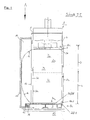
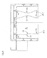
- FIG. 1 shows a side view and partial section — section II — schematically of a baler 1, in which the setting means 16 is partially guided outside the shaft 2a.
- the baler 1 is placed on a footprint 10.
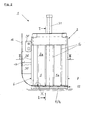
- Your press box 2 comprises, as can also be seen from FIGS. 2 and 3, a base 9 and side walls 6 and 7 erected and projecting thereon, and a rear wall 5, the side walls and the rear wall preferably being made of profile material.
- the front door 8 is pivotally mounted on the side wall 7; for reasons of better clarity, the same is not shown in the other figures.
- the inner sides 6a, 5a, 7a and 8a, the door 8 is open here, circumscribe the shaft 2a in which the waste material is filled and compacted.
- the shaft 2a has a lower pressing area 4 and an upper filling area 3.
- a press plate 36 is guided in the shaft 2a, which is shown here in an upper position, the 'fill in' position, before the start of a press cycle.
- the press plate 36 is driven by a drive unit 31; the control signals come from a control unit 30; this unit 30 can also comprise a hydraulic part, see FIG. 2.
- a cutting agent 16 cut to length is used.
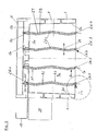
- FIG. 1 and 3 On the inside 9a of the bottom 9 of the shaft 2a, see Figures 1 and 3 are guide units 26, here the special ones Versions 26.1 to 26.4, for the protected inclusion of Sections of the setting means 16 are provided. Any of the ones here multi-part guide unit 26.1 to 26.4 is preferred from two side by side essentially parallel to each other spaced strips 27, 28 between which the Setting agent 16 is guided.
- the guide units 26.1 to 26.4 are also arranged on the floor 9 in such a way that they are aligned with slots 5c provided in the rear wall 5, which are essentially aligned vertically. As can also be seen in FIG. 3, the strips 27, 28 of the guide unit 26 preferably extend into the slots 5c provided in the rear wall 5.
- the mutually facing sections of the rear wall 5 forming a slot 5c are legs 5d and 5d 'directed from the inside 5a to the outside 5b, the slot width preferably narrowing towards the outward ends of the legs.
- the middle areas of the inserted binding agent are in the out of the compensation space 14 provided behind the rear wall, which is defined by a panel 15.
- a panel 15 alternatively can also individual ones arranged laterally from the slots 5c Mudguards are provided in an oblique arrangement to the rear wall 5 can also be baffles.
- the guide unit 26.3 is an example with the Reference number 29 - adjustment directions - also shown that the together with the inside 9a of the bottom 9 the groove-like Groove 26c of the strips 27, 28 forming the guide unit If necessary, the distance between them can also be adjusted can be different on binding agents Sizes are adjustable.
- FIG. 3 also shows that here at the back of the baler 1 in the amount of Bottom 9 arranged quiver 12 and in the central area attached to the side wall 6 or to the rear wall 5 Brackets 13 are provided, which together are a stocker Form for cutting agent 16 cut to length.
- the storage of Setting agent 16 in such a stock is still in the Figures 1 and 2 shown.
- the bracket 13 is arranged so that the stocked binding agent 16, seen from the side, not over the Protruding basic dimensions of the baler 1, see Figure 2.
- the press plate 36 moves into a predetermined position.
- the operator removes the binding agent 16 from a storage 12, 13 provided in the outer region of the baling press, slightly compresses the end regions of the binding agent 16, the end region preferably having an eyelet 16c, and pushes the resulting wire arch, the middle region of the binding agent a vertical slot 5c in the rear wall 5 - Figure 1 -.
- the eyelet 16c is completely pushed onto a fixing pin arranged on the press plate 36.
- the sections following the eyelet 16c, the end region and the region close to the end, of the setting means 16 are introduced through a gap present in the lower side of the press plate 36 and inserted in a guide channel running over the latter and guided into the rear region of the press plate 36 and there pressed into a provided guide part, a spring clip that preferably opens downward.
- the section near the other wire end 16d and the end region of the binding agent 16 run along and on the inside 9a of the bottom 9 in the guide unit 26.1.
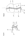
- the lower end 16d of the end region is introduced and temporarily fixed into a labyrinth 21.1 of a wire holder 20.1 arranged on the front 9c of the bottom 9, forming a curve or kink, see FIG. 3a.
- the viewer's gaze here goes from the direction of the left side wall 6 along the front 9c of the base 9 in the direction of the right side wall 7.
- This new way of attaching the end of the binding agent to the front, lower front 9c of the press box 2 has the effect that during the pressing process, in which the operator of the baler approaches the baler several times to fill the filling area 3, no disruptive loops or free ends in the front foot area of the baler are available, as is often the case with conventional balers.
- FIG 3b the detail shown in Figure 3a is in one Top view shown.
- Bottom 9 is on the inside 9a of the guide unit 26.1, consisting of a bar 27 and 28 arranged.
- wire holder 20.1 is on the left-hand side provided by the guide unit 26.1, so that the Guide unit 26.1 inserted binding agent 16 when threading and hold in the wire holder 20.1, guided in the arc against the front inner edge of the bar 27 is pressed and thus a Receives bending stress so that a section of the inside, in the press box into it, along the bottom 9a in the Guide unit 26.1 guided binding agent 16 to the nearest break point - the deflection point "U 3" - is also present under voltage.
- the setting agent is, according to that for the respective Baler type provided number, one or more times, like described above, inserted.
- the wire end 16d of the strapping wire 16 shown is pushed through the eyelet 16c and pulled until the relevant section of the strapping wire 16 abuts on all sides of the finished bale. Subsequently, while the section that is now behind the eyelet is still free, that is to say the remaining end region of the strapping wire, is twisted to form one or more loops, the section of the strapping wire 16 located at the front of the bale is twisted.
- FIGS. 4 and 5 show variants of the arrangement of the groove-like groove 26c which is offset at certain points or in sections.
- each guide unit 26.5 has two sections and three contact points, namely the points "Uo", “U1” and “Un”.
- the lateral offset of the middle contact or deflection point "U1" from the straight line "G" is directed towards the side walls.
- the reference numerals 26.6 and 26.7 show possible variants of the lateral offset of the groove-like groove 26c in sections.
- FIG. 6 shows the positioning of the in a Guide unit 26.1 inserted binding agent 16 shown with 9a denotes the inside of the floor.
- 9a denotes the inside of the floor.
- the groove-like groove 26c is a variant Guide unit 26.8 to said straight line "G" only selectively "P1" ..., "Pn” laterally offset.
- This solution will preferred for rigid, flexible material, e.g. at Plastic straps, used.
Landscapes
- Engineering & Computer Science (AREA)
- Mechanical Engineering (AREA)
- Basic Packing Technique (AREA)
- Separation By Low-Temperature Treatments (AREA)
- Soil Working Implements (AREA)
- Filling Or Discharging Of Gas Storage Vessels (AREA)
- Packaging Of Annular Or Rod-Shaped Articles, Wearing Apparel, Cassettes, Or The Like (AREA)
Abstract
Description
Bei dieser Ballenpresse wird nach dem Pressen des Ballens, vor dem letzten Presshub, durch in der Tür der Ballenpresse vorhandene Schlitze je ein Abbindemittel in die Führungskanäle eingeführt und nachgeschoben, bis selbiges ballenrückseitig an der oberen Fläche des Ballens erscheint. Sodann wird dieses Abbindemittel nach vorn gezogen und nach Ausführung des letzten Presshubes, bei in der unteren Pressstellung befindlichen Pressplatte, die Umschnürung des fertig gepressten Ballens vorgenommen. Nachteilig ist hier insbesondere, dass die in die Führungskanäle eingeschobenen Enden des Abbindemittels während des Einschiebens aus dem Führungskanal heraustreten können und sich im Ballen verhaken; mehrfaches, zeitaufwändiges Einschieben und teilweises Zurückziehen sind hier notwendig.
Bevorzugt findet die Erfindung an Ballenpressen Anwendung, bei denen der mittlere Abschnitt der abgelängten Abbindemittel jeweils durch einen Schlitz in der Rückwand hindurch nach außen geführt, im Wesentlichen einen Bogen beschreibend, in einem hinter der Rückwand vorgesehenem Ausgleichsraum verweilt.
- Figur 1:
- die neue Ballenpresse in einer Seitenansicht im Teilschnitt;
- Figur 2:
- eine Sicht von vorn in den Schacht der Ballenpresse;
- Figur 3:
- eine Draufsicht auf den Presskasten gemäß der in Figur 2 markierten Schnittlinie III-III ;
- Figur 3a und Figur 3b
- Ansichten des Details A aus Figur 3;
- Figur 4 und Figur 5
- eine Ansicht wie in Figur 3 mit Varianten der neuen bodenseitigen Führungseinheiten;
- Figur 6
- das neue Prinzip der bodenseitigen Positionierung des Abbindemittels;
- Figur 7
- eine weitere Variante der besagten Führungseinheiten
und - Figur 8a und Figur 8b
- eine Schnittdarstellung zur Lage des Abbinde-mittels während des Pressens und während des Abbindevorganges.
Frontseitig ist, siehe Figur 1, an der Seitenwand 7 die Fronttür 8 schwenkbar gehaltert; aus Gründen der besseren Übersichtlichkeit ist selbige in den weiteren Figuren nicht dargestellt.
Die Innenseiten 6a, 5a, 7a und 8a, die Tür 8 ist hier geöffnet, umschreiben den Schacht 2a, in welchem das Abfallmaterial eingefüllt sowie verdichtet wird. Der Schacht 2a weist einen unteren Pressbereich 4 und einen oberen Einfüllbereich 3 auf. In dem Schacht 2a wird eine Pressplatte 36 geführt, die hier in einer oberen Position, Position 'Einfüllen', vor dem Beginn eines Presszyklusses, dargestellt ist. Die Pressplatte 36 wird von einer Antriebseinheit 31 angetrieben; die Steuerungssignale kommen von einer Steuereinheit 30; diese Einheit 30 kann auch einen Hydraulikteil umfassen, siehe Figur 2.
Die jeweils einen Schlitz 5c bildenden, einander zugewandten Abschnitte der Rückwand 5, sind von der Innenseite 5a zur Außenseite 5b hin gerichtete Schenkel 5d und 5d', wobei die Schlitzbreite zu den auswärts gerichteten Enden der Schenkel hin vorzugsweise schmäler wird.
Wie in dieser Figur 1 gezeigt, wird die Öse 16c vollständig auf einen auf der Pressplatte 36 angeordneten Fixierstift aufgesteckt.
Der dem anderen Drahtende 16d endnahe Abschnitt und der Endbereich des Abbindemittels 16 verlaufen entlang und auf der Innenseite 9a des Bodens 9 in der Führungseinheit 26.1 . Das untere Ende 16d des Endbereiches wird unter Bildung einer seitlich geführten Kurve bzw. Abknickung in ein Labyrinth 21.1 eines an der Frontseite 9c des Bodens 9 angeordneten Drahthalters 20.1 eingeführt und zeitweise festgelegt, siehe hierzu Figur 3a . Der Blick des Betrachters geht hier aus Richtung der linken Seitenwand 6 entlang der Frontseite 9c des Bodens 9 in Richtung zur rechten Seitenwand 7.
Diese neue Art der Befestigung des Ende des Abbindemittels an der vorderen, unteren Frontseite 9c des Presskastens 2 bewirkt, dass während des Pressvorganges, bei welchem der Bediener der Ballenpresse mehrfach an die Ballenpresse zur Befüllung des Einfüllbereiches 3 herantritt, keine störenden Schlaufen oder freien Enden im frontseitigen Fußbereich der Ballenpresse vorhanden sind, wie dies vielfach bei herkömmlichen Ballenpressen der Fall ist.
Die nach vorn gezogenen Abschnitte des Abbindemittels 16 werden miteinander verbunden. Das Drahtende 16d des gezeigten Umreifungsdrahtes 16 wird durch die Öse 16c geschoben und solange gezogen, bis an allen Seiten des fertigen Ballens der betreffende Abschnitt des Umreifungsdrahtes 16 anliegt. Folgend wird unter Abknickung des jetzt hinter der Öse liegenden noch freien Abschnittes, also der verbliebene Endbereich des Umreifungsdrahtes, unter Bildung von ein oder mehreren Schlaufen, mit dem an der Vorderseite des Ballens befindlichen Abschnittes des Umreifungsdrahtes 16 verdrillt.
In der Figur 5 sind mit den Bezugszeichen 26.6 und 26.7 mögliche Varianten des abschnittsweisen seitlichen Versatzes der nutartigen Rille 26c aufgezeigt.
- 1
- Ballenpresse
- 2
- Presskasten 2a Schacht in Pos.2
- 3
- Einfüllbereich
- 4
- Pressbereich
- 5
- Rückwand
- 5a
- Innenseite (von Pos. 5)
- 5b
- Außenseite (von Pos. 5)
- 5c
- Schlitze (in Pos. 5)
- 5d, 5d'
- Schenkel
- 6
- linke Seitenwand
- 6a
- Innenseite (von Pos. 6)
- 7
- rechte Seitenwand
- 7a
- Innenseite (von Pos. 7)
- 8
- Fronttür
- 8a
- Innenseite (von Pos. 8)
- 9
- Boden
- 9a
- Innenseite (von Pos. 9)
- 9c
- Frontseite (von Pos. 9)
- 10
- Aufstellfläche
- 12
- Köcher (Bevorrater für Pos. 16)
- 13
- Bügel (Bevorrater für Pos. 16)
- 14
- Ausgleichsraum (Verweilraum)
- 15
- Verkleidung
- 16
- Abbindemittel
- 16c
- Drahtenden (Ösen; von Pos. 16)
- 16d
- Drahtenden (von Pos. 16)
- 20.1
- Drahthalter
- 21.1
- Labyrinth
- 26.1..., 26.n
- Führungseinheiten
- 26a
- eine Ende (von Pos. 26.1..., 26.n)
- 26b
- andere Ende (von Pos. 26.1..., 26.n)
- 26c
- nutartige Rille (von Pos. 26.1..., 26.n)
- 27, 28
- Leisten (von Pos. 26.1..., 26.n)
- 29
- Verstellrichtungen
- 30
- Steuereinheiten (Steuereinheiten)
- 31
- Antriebseinheit
- 36
- Pressplatte
- G
- gedachte Gerade
- A1..., An
- Abschnitte (von Pos. 26.1..., 26.n)
- P1..., Pn
- punktueller Versatz (von Pos. 26.1..., 26.n)
- Uo..., Un
- Anlage- bzw. Umlenkpunkte
Claims (13)
- Ballenpresse,dadurch gekennzeichnet, dass wenigstens die nutartige Rille (26c) der Führungseinheit (26.1..., 26.n) punktuell (P1..., Pn) und/oder abschnittsweise (A1 ..., An) seitlich versetzt zu einer gedachten Geraden (G) angeordnet ist, wobei diese Gerade (G) im Wesentlichen durch Symmetrieachspunkte der jeweiligen Fläche der Enden (26a und 26b) von selbiger (26.1..., 26.n) oder einer parallelen Achse zu der genannten Geraden (G) vorbestimmt ist.die einen Presskasten (2) aufweist, miteinem im Wesentlichen vertikalen Schacht (2a), der oberhalb seines Bodens (9) einen Pressbereich (4) und einen darüber liegenden Einfüllbereich (3) besitzt, in denen (4, 3) eine Pressplatte (36) bewegbar ist,wobei der Schacht (2a) von einer Rückwand (5) und zwei einander gegenüberliegenden Seitenwänden (6,7) sowie einer wenigstens den Pressbereich (4) verschließenden Fronttür (8) gebildet ist,und bei der wenigstens auf oder im Boden (9) des Schachtes (2a) wenigstens eine Führungseinheit ( 26.1..., 26.n) zur Aufnahme / Führung von Abbindemittel (16) vorgesehen ist,deren (26.1...., 26.n) eines Ende (26a) zur Rückwand (5) und deren anderes Ende (26b) zur Frontseite (9c) des Bodens (9) zeigtund eine die Enden (26a, 26b) durchschreitende, durchgängige nutartige Rille (26c) enthält,
- Ballenpresse nach Anspruch 1,
dadurch gekennzeichnet, dass die Führungseinheit (26.1..., 26.n) selbst punktuell (P1..., Pn) und/oder abschnittsweise (A1..., An) seitlich zur besagten vorbestimmten Geraden (G) versetzt angeordnet ist. - Anspruch nach 1 oder 2,
dadurch gekennzeichnet, dass die seitlich versetzten Punkte (P1..., Pn) bzw. Abschnitte (A1..., An) der Führungseinheit (26.1..., 26.n) bzw. der nutartigen Rille (26c) zu der gedachten Geraden (G) alternierend angeordnet sind. - Ballenpresse nach wenigstens einem der vorhergehenden Ansprüche 1 bis 3,
dadurch gekennzeichnet, dass die Führungseinheit (26.2..., 26.n) einstückig ausgebildet ist. - Ballenpresse nach wenigstens einem der vorhergehenden Ansprüche 1 bis 3,
dadurch gekennzeichnet, dass die Führungseinheit (26.1..., 26.n) mehrteilig ausgeführt ist, vorzugsweise zwei Leisten (27, 28) umfasst, wobei die mit Abstand zueinander angeordneten Leisten (27, 28) unter Einschluss des zwischen ihnen befindlichen Bodens (9, 9a) jeweils die nutartige Rille (26c) bilden. - Ballenpresse nach wenigstens einem der vorhergehenden Ansprüche 1 bis 5 ,
dadurch gekennzeichnet, dass an der Frontseite (9c) des Bodens (9), jeweils einer Führungseinheit (26.1..., 26.n) zugeordnet und seitlich von dieser angeordnet, ein ein Labyrinth (21.1) aufweisender Drahthalter (20.1) derart vorgesehen ist, das dass zu arretierende Ende (16d) des Abbindemittels (16) seine Elastizitätsgrenze beim Arretiervorgang und während seiner Arretierung nicht überschreitet. - Ballenpresse nach wenigstens einem der Ansprüche 1 bis 6,
dadurch gekennzeichnet, dass die nutenartige Rille (26c); einen unförmigen, schwalbenschwanzförmigen oder bi-konkaven Querschnitt besitzt. - Ballenpresse nach wenigstens einem der Ansprüche 5 und 7,
dadurch gekennzeichnet, dass die auf der Innenseite (9a) des Bodens (9) des Schachtes (2a) vorgesehenen Leisten (27 und 28) der Führungseinheiten (26.1..., 26n) zur Einstellung ihres Abstandes zueinander verschiebbar und arretierbar angeordnet sind. - Ballenpresse nach wenigstens einem der vorhergehenden Ansprüche 5 bis 8,
dadurch gekennzeichnet, dass die zur Rückwand (5) zeigenden Enden der Leisten (27, 28) der bodenseitigen Führungseinheiten (26) jeweils bis in Schlitze (5c) der Rückwand (5) hineinreichen. - Ballenpresse nach wenigstens einem der vorhergehenden Ansprüche 5 bis 9,
dadurch gekennzeichnet, dass die rückwandseitigen Enden (26a) der Leisten (27, 28) nach oben gebogen oder abgewinkelt sind. - Ballenpresse nach wenigstens einem der vorhergehenden Ansprüche 5 bis 10,
dadurch gekennzeichnet, dass an der Außenseite (5b) der Rückwand (5) ein Ausgleichsraum (14) für die durch die Rückwand (5) hindurch reichenden Abschnitte (16e) der Abbindemittel (16) vorgesehen ist. - Ballenpresse nach Anspruch 11,
dadurch gekennzeichnet, dass der Ausgleichsraum (14) durch eine Verkleidung (15), vorzugsweise allseits, gesichert ist. - Ballenpresse nach wenigstens einem der vorhergehenden Ansprüche 5 bis 12,
dadurch gekennzeichnet, dass bevorzugt im Bereich der Rückwand (5), unterhalb der Verkleidung (15) quer liegend, ein Bevorrater für Abbindemittel (16) in Form eines Köchers (12) vorgesehen ist, wobei dieser Bevorrater durch einen seitwärts an einer der Seitenwände (6 bzw. 7) angeordneten Bügel (13) ergänzt ist.
Applications Claiming Priority (2)
| Application Number | Priority Date | Filing Date | Title |
|---|---|---|---|
| DE20202531U DE20202531U1 (de) | 2002-02-18 | 2002-02-18 | Ballenpresse |
| DE20202531U | 2002-02-18 |
Publications (3)
| Publication Number | Publication Date |
|---|---|
| EP1336566A2 true EP1336566A2 (de) | 2003-08-20 |
| EP1336566A3 EP1336566A3 (de) | 2003-09-17 |
| EP1336566B1 EP1336566B1 (de) | 2005-05-04 |
Family
ID=7967958
Family Applications (1)
| Application Number | Title | Priority Date | Filing Date |
|---|---|---|---|
| EP03003500A Expired - Lifetime EP1336566B1 (de) | 2002-02-18 | 2003-02-15 | Ballenpresse |
Country Status (4)
| Country | Link |
|---|---|
| EP (1) | EP1336566B1 (de) |
| AT (1) | ATE294737T1 (de) |
| DE (3) | DE20202531U1 (de) |
| ES (1) | ES2242110T3 (de) |
Families Citing this family (2)
| Publication number | Priority date | Publication date | Assignee | Title |
|---|---|---|---|---|
| EP2668027A1 (de) * | 2011-01-28 | 2013-12-04 | AUTEFA Solutions Germany GmbH | Ballenpresse und verfahren zur herstellung verdichteter pressbalen aus faser material |
| DE102012202437A1 (de) * | 2012-02-17 | 2013-08-22 | Sib Strautmann Ingenieurbüro Gmbh | Presse zum Herstellen von Pressballen, Abbindeeinrichtung und Nachpresseinrichtung |
Family Cites Families (4)
| Publication number | Priority date | Publication date | Assignee | Title |
|---|---|---|---|---|
| US4041856A (en) * | 1975-09-26 | 1977-08-16 | Anthony Fox | Baling machine with improved platen drive and guide assembly |
| GB1594668A (en) * | 1978-05-26 | 1981-08-05 | Tyne Truck & Trolley Co Ltd | Power operated baling press |
| US4232599A (en) * | 1978-10-19 | 1980-11-11 | J. V. Manufacturing & Welding, Inc. | Waste paper compacter with front access features |
| US5379687A (en) * | 1994-02-04 | 1995-01-10 | Continental Eagle Corporation | Bale wire tie apparatus and method |
-
2002
- 2002-02-18 DE DE20202531U patent/DE20202531U1/de not_active Expired - Lifetime
-
2003
- 2003-02-15 DE DE10306355A patent/DE10306355A1/de not_active Withdrawn
- 2003-02-15 ES ES03003500T patent/ES2242110T3/es not_active Expired - Lifetime
- 2003-02-15 AT AT03003500T patent/ATE294737T1/de not_active IP Right Cessation
- 2003-02-15 EP EP03003500A patent/EP1336566B1/de not_active Expired - Lifetime
- 2003-02-15 DE DE50300497T patent/DE50300497D1/de not_active Expired - Lifetime
Also Published As
| Publication number | Publication date |
|---|---|
| EP1336566B1 (de) | 2005-05-04 |
| ATE294737T1 (de) | 2005-05-15 |
| DE50300497D1 (de) | 2005-06-09 |
| ES2242110T3 (es) | 2005-11-01 |
| DE20202531U1 (de) | 2003-04-24 |
| EP1336566A3 (de) | 2003-09-17 |
| DE10306355A1 (de) | 2003-09-04 |
Similar Documents
| Publication | Publication Date | Title |
|---|---|---|
| EP3323603B1 (de) | Horizontale ballenpresse mit einer ballenabbindevorrichtung | |
| DE2419151A1 (de) | Vorrichtung zum umschnueren von ballen | |
| EP0084620B1 (de) | Vorrichtung zum Umschnüren von Ballen | |
| DE4446748C2 (de) | Verfahren zum manuellen Abbinden von Ballen in Abfallpressen und Vorrichtung zur Verfahrensdurchführung | |
| DE102021112704A1 (de) | Verfahren zum Verändern der Umreifung sowie Ballenpresse zur Anwendung dieses Verfahrens | |
| DE102012008554A1 (de) | Kanalballenpresse | |
| DE3436883A1 (de) | Verfahren zum herstellen von rechteckigen grossballen aus geschnittenem halmgut und grossballenpresse | |
| EP2292418B1 (de) | Ballenpresse | |
| EP1336566B1 (de) | Ballenpresse | |
| DE10390331B4 (de) | Anordnung zum Umschnüren von Ballen in einer Ballenpresse | |
| DE10131165B4 (de) | Verfahren und Vorrichtung zum Abbinden eines Ballens in Ballenpressen | |
| DE8710185U1 (de) | Werkzeug für das Abbinden von Kabelbündeln o.dgl. mit einem endlosen Band | |
| EP2478757B1 (de) | Ballenpresse | |
| DE202013012192U1 (de) | Kanalballenpresse | |
| DE10201797B4 (de) | Ballenpresse | |
| DE2745864C2 (de) | Ballenpresse | |
| DE3238542C2 (de) | ||
| DE2046042A1 (de) | Stanz und Bindemaschine | |
| DE2446953A1 (de) | Kanalpresse zur herstellung von verschnuerten ballen aus vorwiegend nichtmetallischem pressgut | |
| DE4231825A1 (de) | Ballenpresse, insbesondere zur Verdichtung von Verpackungsmaterial | |
| DE10106094B4 (de) | Ballenpresse | |
| EP3882166B1 (de) | Verfahren zum einfädeln des unteren umreifungs-stranges sowie ballenpresse zur anwendung dieses verfahrens | |
| DE2552722A1 (de) | Kanalpresse mit einem mit schermessern und schnuernuten versehenen presstempel | |
| DE102008010155A1 (de) | Verfahren und Vorrichtung zum Abbinden eines Ballens | |
| DE4203360A1 (de) | Vorrichtung zum abbinden von pressballen mit hilfe von bindematerial |
Legal Events
| Date | Code | Title | Description |
|---|---|---|---|
| PUAI | Public reference made under article 153(3) epc to a published international application that has entered the european phase |
Free format text: ORIGINAL CODE: 0009012 |
|
| PUAL | Search report despatched |
Free format text: ORIGINAL CODE: 0009013 |
|
| AK | Designated contracting states |
Designated state(s): AT BE BG CH CY CZ DE DK EE ES FI FR GB GR HU IE IT LI LU MC NL PT SE SI SK TR |
|
| AX | Request for extension of the european patent |
Extension state: AL LT LV MK RO |
|
| AK | Designated contracting states |
Kind code of ref document: A3 Designated state(s): AT BE BG CH CY CZ DE DK EE ES FI FR GB GR HU IE IT LI LU MC NL PT SE SI SK TR |
|
| AX | Request for extension of the european patent |
Extension state: AL LT LV MK RO |
|
| RIC1 | Information provided on ipc code assigned before grant |
Ipc: 7B 65B 27/12 A Ipc: 7B 30B 9/30 B |
|
| 17P | Request for examination filed |
Effective date: 20040315 |
|
| AKX | Designation fees paid |
Designated state(s): AT BE BG CH CY CZ DE DK EE ES FI FR GB GR HU IE IT LI LU MC NL PT SE SI SK TR |
|
| GRAP | Despatch of communication of intention to grant a patent |
Free format text: ORIGINAL CODE: EPIDOSNIGR1 |
|
| GRAS | Grant fee paid |
Free format text: ORIGINAL CODE: EPIDOSNIGR3 |
|
| GRAA | (expected) grant |
Free format text: ORIGINAL CODE: 0009210 |
|
| AK | Designated contracting states |
Kind code of ref document: B1 Designated state(s): AT BE BG CH CY CZ DE DK EE ES FI FR GB GR HU IE IT LI LU MC NL PT SE SI SK TR |
|
| PG25 | Lapsed in a contracting state [announced via postgrant information from national office to epo] |
Ref country code: IT Free format text: LAPSE BECAUSE OF FAILURE TO SUBMIT A TRANSLATION OF THE DESCRIPTION OR TO PAY THE FEE WITHIN THE PRESCRIBED TIME-LIMIT;WARNING: LAPSES OF ITALIAN PATENTS WITH EFFECTIVE DATE BEFORE 2007 MAY HAVE OCCURRED AT ANY TIME BEFORE 2007. THE CORRECT EFFECTIVE DATE MAY BE DIFFERENT FROM THE ONE RECORDED. Effective date: 20050504 Ref country code: SI Free format text: LAPSE BECAUSE OF FAILURE TO SUBMIT A TRANSLATION OF THE DESCRIPTION OR TO PAY THE FEE WITHIN THE PRESCRIBED TIME-LIMIT Effective date: 20050504 Ref country code: CZ Free format text: LAPSE BECAUSE OF FAILURE TO SUBMIT A TRANSLATION OF THE DESCRIPTION OR TO PAY THE FEE WITHIN THE PRESCRIBED TIME-LIMIT Effective date: 20050504 Ref country code: SK Free format text: LAPSE BECAUSE OF FAILURE TO SUBMIT A TRANSLATION OF THE DESCRIPTION OR TO PAY THE FEE WITHIN THE PRESCRIBED TIME-LIMIT Effective date: 20050504 Ref country code: FI Free format text: LAPSE BECAUSE OF FAILURE TO SUBMIT A TRANSLATION OF THE DESCRIPTION OR TO PAY THE FEE WITHIN THE PRESCRIBED TIME-LIMIT Effective date: 20050504 Ref country code: NL Free format text: LAPSE BECAUSE OF FAILURE TO SUBMIT A TRANSLATION OF THE DESCRIPTION OR TO PAY THE FEE WITHIN THE PRESCRIBED TIME-LIMIT Effective date: 20050504 Ref country code: IE Free format text: LAPSE BECAUSE OF FAILURE TO SUBMIT A TRANSLATION OF THE DESCRIPTION OR TO PAY THE FEE WITHIN THE PRESCRIBED TIME-LIMIT Effective date: 20050504 |
|
| REG | Reference to a national code |
Ref country code: GB Ref legal event code: FG4D Free format text: NOT ENGLISH |
|
| REG | Reference to a national code |
Ref country code: CH Ref legal event code: EP |
|
| REG | Reference to a national code |
Ref country code: IE Ref legal event code: FG4D Free format text: LANGUAGE OF EP DOCUMENT: GERMAN |
|
| REF | Corresponds to: |
Ref document number: 50300497 Country of ref document: DE Date of ref document: 20050609 Kind code of ref document: P |
|
| PG25 | Lapsed in a contracting state [announced via postgrant information from national office to epo] |
Ref country code: DK Free format text: LAPSE BECAUSE OF FAILURE TO SUBMIT A TRANSLATION OF THE DESCRIPTION OR TO PAY THE FEE WITHIN THE PRESCRIBED TIME-LIMIT Effective date: 20050804 Ref country code: GR Free format text: LAPSE BECAUSE OF FAILURE TO SUBMIT A TRANSLATION OF THE DESCRIPTION OR TO PAY THE FEE WITHIN THE PRESCRIBED TIME-LIMIT Effective date: 20050804 Ref country code: BG Free format text: LAPSE BECAUSE OF FAILURE TO SUBMIT A TRANSLATION OF THE DESCRIPTION OR TO PAY THE FEE WITHIN THE PRESCRIBED TIME-LIMIT Effective date: 20050804 Ref country code: SE Free format text: LAPSE BECAUSE OF FAILURE TO SUBMIT A TRANSLATION OF THE DESCRIPTION OR TO PAY THE FEE WITHIN THE PRESCRIBED TIME-LIMIT Effective date: 20050804 |
|
| GBT | Gb: translation of ep patent filed (gb section 77(6)(a)/1977) |
Effective date: 20050906 |
|
| PG25 | Lapsed in a contracting state [announced via postgrant information from national office to epo] |
Ref country code: PT Free format text: LAPSE BECAUSE OF FAILURE TO SUBMIT A TRANSLATION OF THE DESCRIPTION OR TO PAY THE FEE WITHIN THE PRESCRIBED TIME-LIMIT Effective date: 20051017 |
|
| NLV1 | Nl: lapsed or annulled due to failure to fulfill the requirements of art. 29p and 29m of the patents act | ||
| REG | Reference to a national code |
Ref country code: ES Ref legal event code: FG2A Ref document number: 2242110 Country of ref document: ES Kind code of ref document: T3 |
|
| PG25 | Lapsed in a contracting state [announced via postgrant information from national office to epo] |
Ref country code: HU Free format text: LAPSE BECAUSE OF FAILURE TO SUBMIT A TRANSLATION OF THE DESCRIPTION OR TO PAY THE FEE WITHIN THE PRESCRIBED TIME-LIMIT Effective date: 20051105 |
|
| REG | Reference to a national code |
Ref country code: IE Ref legal event code: FD4D |
|
| PG25 | Lapsed in a contracting state [announced via postgrant information from national office to epo] |
Ref country code: AT Free format text: LAPSE BECAUSE OF NON-PAYMENT OF DUE FEES Effective date: 20060215 |
|
| PG25 | Lapsed in a contracting state [announced via postgrant information from national office to epo] |
Ref country code: LU Free format text: LAPSE BECAUSE OF NON-PAYMENT OF DUE FEES Effective date: 20060228 Ref country code: BE Free format text: LAPSE BECAUSE OF NON-PAYMENT OF DUE FEES Effective date: 20060228 Ref country code: MC Free format text: LAPSE BECAUSE OF NON-PAYMENT OF DUE FEES Effective date: 20060228 |
|
| PLBE | No opposition filed within time limit |
Free format text: ORIGINAL CODE: 0009261 |
|
| STAA | Information on the status of an ep patent application or granted ep patent |
Free format text: STATUS: NO OPPOSITION FILED WITHIN TIME LIMIT |
|
| ET | Fr: translation filed | ||
| 26N | No opposition filed |
Effective date: 20060207 |
|
| PG25 | Lapsed in a contracting state [announced via postgrant information from national office to epo] |
Ref country code: CH Free format text: LAPSE BECAUSE OF NON-PAYMENT OF DUE FEES Effective date: 20070228 Ref country code: LI Free format text: LAPSE BECAUSE OF NON-PAYMENT OF DUE FEES Effective date: 20070228 |
|
| REG | Reference to a national code |
Ref country code: CH Ref legal event code: PL |
|
| BERE | Be: lapsed |
Owner name: SCHWELLING, HERMANN Effective date: 20060228 |
|
| PG25 | Lapsed in a contracting state [announced via postgrant information from national office to epo] |
Ref country code: EE Free format text: LAPSE BECAUSE OF FAILURE TO SUBMIT A TRANSLATION OF THE DESCRIPTION OR TO PAY THE FEE WITHIN THE PRESCRIBED TIME-LIMIT Effective date: 20050504 |
|
| PG25 | Lapsed in a contracting state [announced via postgrant information from national office to epo] |
Ref country code: TR Free format text: LAPSE BECAUSE OF FAILURE TO SUBMIT A TRANSLATION OF THE DESCRIPTION OR TO PAY THE FEE WITHIN THE PRESCRIBED TIME-LIMIT Effective date: 20050504 |
|
| PG25 | Lapsed in a contracting state [announced via postgrant information from national office to epo] |
Ref country code: CY Free format text: LAPSE BECAUSE OF FAILURE TO SUBMIT A TRANSLATION OF THE DESCRIPTION OR TO PAY THE FEE WITHIN THE PRESCRIBED TIME-LIMIT Effective date: 20050504 |
|
| REG | Reference to a national code |
Ref country code: DE Ref legal event code: R082 Ref document number: 50300497 Country of ref document: DE Representative=s name: KANZLEI "REGION GOEPPINGEN" (GBR) PATENTANWALT, DE Ref country code: DE Ref legal event code: R082 Ref document number: 50300497 Country of ref document: DE Representative=s name: WEICKMANN & WEICKMANN PATENTANWAELTE - RECHTSA, DE Ref country code: DE Ref legal event code: R082 Ref document number: 50300497 Country of ref document: DE Representative=s name: WEICKMANN & WEICKMANN PATENT- UND RECHTSANWAEL, DE |
|
| REG | Reference to a national code |
Ref country code: FR Ref legal event code: PLFP Year of fee payment: 14 |
|
| REG | Reference to a national code |
Ref country code: DE Ref legal event code: R082 Ref document number: 50300497 Country of ref document: DE Representative=s name: WEICKMANN & WEICKMANN PATENTANWAELTE - RECHTSA, DE Ref country code: DE Ref legal event code: R082 Ref document number: 50300497 Country of ref document: DE Representative=s name: WEICKMANN & WEICKMANN PATENT- UND RECHTSANWAEL, DE |
|
| REG | Reference to a national code |
Ref country code: FR Ref legal event code: PLFP Year of fee payment: 15 |
|
| REG | Reference to a national code |
Ref country code: FR Ref legal event code: PLFP Year of fee payment: 16 |
|
| PGFP | Annual fee paid to national office [announced via postgrant information from national office to epo] |
Ref country code: ES Payment date: 20180301 Year of fee payment: 16 Ref country code: DE Payment date: 20180226 Year of fee payment: 16 Ref country code: GB Payment date: 20180221 Year of fee payment: 16 |
|
| PGFP | Annual fee paid to national office [announced via postgrant information from national office to epo] |
Ref country code: FR Payment date: 20180226 Year of fee payment: 16 |
|
| REG | Reference to a national code |
Ref country code: DE Ref legal event code: R119 Ref document number: 50300497 Country of ref document: DE |
|
| GBPC | Gb: european patent ceased through non-payment of renewal fee |
Effective date: 20190215 |
|
| PG25 | Lapsed in a contracting state [announced via postgrant information from national office to epo] |
Ref country code: GB Free format text: LAPSE BECAUSE OF NON-PAYMENT OF DUE FEES Effective date: 20190215 Ref country code: DE Free format text: LAPSE BECAUSE OF NON-PAYMENT OF DUE FEES Effective date: 20190903 |
|
| PG25 | Lapsed in a contracting state [announced via postgrant information from national office to epo] |
Ref country code: FR Free format text: LAPSE BECAUSE OF NON-PAYMENT OF DUE FEES Effective date: 20190228 |
|
| REG | Reference to a national code |
Ref country code: ES Ref legal event code: FD2A Effective date: 20200330 |
|
| PG25 | Lapsed in a contracting state [announced via postgrant information from national office to epo] |
Ref country code: ES Free format text: LAPSE BECAUSE OF NON-PAYMENT OF DUE FEES Effective date: 20190216 |