EP1336711A2 - Ferrure pour le verrouillage entre une fenêtre ou une porte et un dormant, gâche pour une telle ferrure et procédé d'ouverture de la fenêtre ou de la porte - Google Patents
Ferrure pour le verrouillage entre une fenêtre ou une porte et un dormant, gâche pour une telle ferrure et procédé d'ouverture de la fenêtre ou de la porte Download PDFInfo
- Publication number
- EP1336711A2 EP1336711A2 EP03001645A EP03001645A EP1336711A2 EP 1336711 A2 EP1336711 A2 EP 1336711A2 EP 03001645 A EP03001645 A EP 03001645A EP 03001645 A EP03001645 A EP 03001645A EP 1336711 A2 EP1336711 A2 EP 1336711A2
- Authority
- EP
- European Patent Office
- Prior art keywords
- window
- pin
- slot
- handle
- plate
- Prior art date
- Legal status (The legal status is an assumption and is not a legal conclusion. Google has not performed a legal analysis and makes no representation as to the accuracy of the status listed.)
- Withdrawn
Links
- 238000000034 method Methods 0.000 title claims description 8
- 235000001674 Agaricus brunnescens Nutrition 0.000 claims description 13
- 230000035515 penetration Effects 0.000 description 10
- 238000013475 authorization Methods 0.000 description 3
- 238000004519 manufacturing process Methods 0.000 description 3
- 238000005452 bending Methods 0.000 description 1
- 230000005540 biological transmission Effects 0.000 description 1
- 238000011161 development Methods 0.000 description 1
- 230000018109 developmental process Effects 0.000 description 1
- 239000011521 glass Substances 0.000 description 1
- 238000003780 insertion Methods 0.000 description 1
- 230000037431 insertion Effects 0.000 description 1
- 239000000463 material Substances 0.000 description 1
- 230000008961 swelling Effects 0.000 description 1
- 230000007704 transition Effects 0.000 description 1
Images


Classifications
-
- E—FIXED CONSTRUCTIONS
- E05—LOCKS; KEYS; WINDOW OR DOOR FITTINGS; SAFES
- E05C—BOLTS OR FASTENING DEVICES FOR WINGS, SPECIALLY FOR DOORS OR WINDOWS
- E05C9/00—Arrangements of simultaneously actuated bolts or other securing devices at well-separated positions on the same wing
- E05C9/18—Details of fastening means or of fixed retaining means for the ends of bars
- E05C9/1825—Fastening means
- E05C9/1833—Fastening means performing sliding movements
- E05C9/185—Fastening means performing sliding movements parallel with actuating bar
- E05C9/1858—Fastening means performing sliding movements parallel with actuating bar of the roller bolt type
-
- E—FIXED CONSTRUCTIONS
- E05—LOCKS; KEYS; WINDOW OR DOOR FITTINGS; SAFES
- E05C—BOLTS OR FASTENING DEVICES FOR WINGS, SPECIALLY FOR DOORS OR WINDOWS
- E05C9/00—Arrangements of simultaneously actuated bolts or other securing devices at well-separated positions on the same wing
- E05C9/18—Details of fastening means or of fixed retaining means for the ends of bars
- E05C9/1808—Keepers
Definitions
- the present invention relates to a device for locking a Window or a door on a frame according to the generic term of Claim 1, and a striking plate for a device for locking a window or a door on a frame according to the generic term of claim 4, and a method for opening a window or a door with a turn-tilt fitting.
- the present invention is based on the knowledge that the window or the Door can be moved vertically within the frame, since the window or the door is inserted into the frame with a certain amount of play. This Play is necessary so that the window or door in the frame can be installed and opened and closed without clamping can. This game also allows some swelling and shrinking of the Window / door, e.g. B. depending on the temperatures. This game is usually 2 to 3 mm, but can be due to manufacturing reasons Tolerances are also larger. Furthermore, the present Invention based on the knowledge that in the device for locking the Window or door, often called hardware, itself manufacturing-related tolerances there is a clearance of 2 mm to 4 mm. in the On average, a tolerance of 3 mm is expected.
- the gear stroke is 17 mm and Diameter of the pin 9 mm, so that an effective depth of 5 mm remains.
- a burglar needs the window / the Only move the door and frame vertically in the frame by 5 mm and the pin already comes out of its engagement in the locking plate and the window or door can be opened without authorization.
- the present invention is based on the object to increase the effective depth of engagement of the pin in the slot of the locking plate, to make unauthorized opening of the window or door more difficult or even to prevent.
- a device is used as a technical solution to this problem with the features of claim 1, a strike plate with the features of Claim 4 and a method with the features of claim 7 proposed.
- Advantageous developments of the device, the striking plate and the procedure can be found in the respective subclaims.
- the handle In the known windows or doors, the handle is only pivoted by 90 °, to lead the pin out of engagement in the locking plate.
- a fitting designed according to this technical teaching has the advantage that the rotation of the handle is much larger at 95 ° to 180 °, and that thus a lot of the connecting element and consequently also of the pin longer distance can be covered. In other words, due to the increased swivel angle of the handle, the gear stroke enlarged accordingly.
- This larger gear stroke means that the pin is much deeper the slot of the striker plate can be inserted so that the window or the door needs to be moved vertically by a much larger distance to be opened without authorization. If within the scope of funds locks are provided, the horizontal increases in an analogous manner Direction of travel of the window to get this out of the locking plate lead out without authorization.
- the gear stroke can be achieved with a commercially available fitting from previously 17 mm to 22 mm.
- the Penetration depth of the pin in the slot from 14 mm to 19 mm elevated. It has proven advantageous to extend the length of the slot 19 mm to 23 mm, preferably 22 mm to increase.
- the pin is a mushroom head educated. This has the advantage that the mushroom head is not just in the slot of the Engages locking plate, but engages behind it. This will make a additional security standard achieved.
- a striking plate designed according to the above-mentioned technical teaching has the advantage that the pin, which is designed as a mushroom head, is close to the locking plate can be inserted over into the slot because of the diameter wider mushroom head in the area of the recess on the connecting web becomes. This enables the stroke or the effective penetration depth be increased, as the mushroom head is no longer on the striker plate needs to be led past. In other words, half of the Diameter difference between mushroom head and cone can now be used around the gear stroke or the effective penetration depth enlarge.
- the connecting web is not formed perpendicular to the locking plate, but preferably by 20 ° from the vertical inclined. That is, between the striking plate and the The connecting web has an angle of 30 ° to 85 °, preferably 70 °. This ensures that the web between the slot and the front edge of the Strike plate is widened, so that the stability of the striker plate increases becomes. As a result, unauthorized opening by bending the locking plate prevented.
- Fig. 1 shows a commercially available, enclosed in a frame 10 window 12, the window 12 comprising a frame 14 and a glass pane 16.
- This window 12 can be locked by means of a device on the frame 10 can be locked.
- the device shown here is is a pure rotary fitting, however, this device can be in one another embodiment can also be designed as a turn-tilt fitting.
- a handle 18 is integrated, which does not have a here shown transmission on a metallic, elongated connecting element 20th acts, which on the narrow side facing the frame 10 Frame 14 is arranged.
- the connecting element 20 is vertical protruding, attached to the frame 10 facing a pin 22 on the distal end of which is formed a mushroom head 24.
- the connecting element 20 can together with the pin 22 through the handle 18 in the vertical direction be moved up and down.
- a gear stroke is defined via the difference between the highest and the lowest position of the pin 22nd
- the handle 18 is moved in the direction of the Arrow 32 rotated upwards by 115 °. In Fig. 1, this position is dashed shown. Accordingly, the pin 22 corresponding to Gear stroke turned down, thus from the slot 26 and the Closing plate 28 led out. Now the window 12 can be pulled Handle 18 can be opened.
- the handle 18 of the window 12 is not only rotated by 90 °, but rather by 115 °. Through this larger turning path The gear stroke also increases, so that the pin 22 also unites covered a much larger distance. This makes it possible to slot 26 of the closing plate 28 to be longer so that unauthorized opening of the Window difficult by prying out the frame or even to prevent.
- the handle is also around more than 115 °, in individual cases up to 180 °. Yourself Turning the handle by only 95 ° increases the gear stroke and thus a deeper penetration of the pin 22 into the slot 26.
- a striking plate 34 is shown, as in the 1 is used.
- This striking plate 34 comprises one Closing plate 28 with two slots 26 arranged opposite one another, a mounting plate 30 and a connecting web 36.
- the connecting web Closing plate 28 connected, the connecting web 36 at an angle is inclined by approximately 70 ° with respect to the closing plate 28.
- This striker plate 28 is via rivets, not shown here, to the fastening plate 30 riveted.
- the striking plate 34 is designed such that the front edge 38 of the connecting web 36 comes to rest on the edge of the frame to one to realize a flush transition from the frame to the striking plate 34.
- the connecting web 36 which is inclined relative to the closing plate 28 the locking plate 28 protrude about 1 mm to 2 mm above the frame, whereby the arm 40 can be made widened by 1 mm to 2 mm. It is now difficult to bend slot 26 violently possible.
- the connecting web 36 has a recess 42, in the area of which Mushroom head 24 can be guided past the closing plate 28. This is it possible, the pin 22 very close to the arm 40 of the slot 26 and the mushroom head 24 pass very close to the connecting web 36 so that the pin 22 gets into slot 26 without much play. This exploitation of the least play increases the possible gear stroke or the effective Penetration depth of the pin in the slot 26.
- the measures according to the invention make it possible to determine the depth of the Slit 26 to increase from previously 14 mm to 22 mm, so that in this Embodiment, the effective depth of penetration of the pin 22 in the slot 26th from previously 5 mm (prior art) to 13 mm.
- the Strike plate 34 is axially symmetrical and can thus be optional mounted on left or right hinged windows or doors. It is understood that the striking plate 34 in a not shown here Embodiment can only be carried out in half, especially around Save material costs.
- FIGS. 4 and 5 is an alternative embodiment of a striking plate 35 shown, in which the connecting web 36 via a connecting plate 43 is connected to the closing plate 29.
- the connecting plate 43 can connected in one piece to the connecting web 36 and on the closing plate 29 be welded on. This will force the striking plate to bend open 35 further complicated or even prevented. Otherwise this corresponds Strike plate 35 that shown in FIGS. 2 and 3.
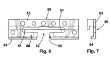
- FIG. 5 and 6 is a third embodiment of an inventive Strike plate 50 shown.
- This striking plate is a tilt holder executed, that is, the access to the slots 51 is arranged on the inside and the slots 51 are accessible through a common opening 52.
- the striking plate 50 is analogous to the striking plate 34 according to FIGS. 2 and 3 trained.
- the striking plate 50 also includes a striking plate 53 on which a Connecting web 54 is angled, the angle between Closing plate 53 and connecting web 54 is approximately 70 °.
- the Connecting web 54 has a recess 56, in the area of which Mushroom head 24 can be guided past the closing plate 53. This is it possible, the pin 22 very close to the arm 58 of the slot 51 and the mushroom head 24 pass very close to the connecting web 54 so that the pin 22 gets into slot 51 without much play. This exploitation of the least play increases the possible gear stroke or the effective Penetration depth of the pin in the slot 51 even with a tilt holder.
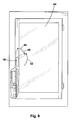
- FIG. 8 shows a further embodiment of a window according to the invention shown, which is essentially the embodiment shown in Fig. 1 equivalent.
- the window 44 8 has a turn-tilt fitting.
- To open the window 44 it is now proposed to first handle 18 in the direction of arrow 32 and then in the direction of arrow 46 to its tilt position rotate. If you then move the handle 18 back in the direction of arrow 48 in its open position (rotated 115 ° compared to the closed position), the window 44 can now be turned and opened by pulling the handle become.
- This measure makes the game inherent in the fitting reduced so that the stroke and the depth of penetration of the pin 22 in the slot 26 can be enlarged. It is not necessary to use the handle 18 to move to the stop in the vertical position, but it is rather sufficient, the handle 18 beyond the open position (115 °) and then move back to the open position.
- the inventive one Closing sequence applied to fittings according to the state of the art. This means that even with the known fittings can be turned by turning the handle beyond the open position and then turning the handle into Open position (90 ° compared to the basic position) the game is switched off so that the stroke or effective penetration depth is increased by approximately 2 mm become. Consequently, the otherwise conventional fittings Pin-receiving slot can be extended by this 2 mm, provided that proposed closing sequence is observed. Already this increased by 2 mm effective depth of penetration makes it difficult to pry open the window / door considerably.
Landscapes
- Engineering & Computer Science (AREA)
- Mechanical Engineering (AREA)
- Lock And Its Accessories (AREA)
- Pinball Game Machines (AREA)
Applications Claiming Priority (2)
| Application Number | Priority Date | Filing Date | Title |
|---|---|---|---|
| DE10202576 | 2002-01-24 | ||
| DE2002102576 DE10202576B4 (de) | 2002-01-24 | 2002-01-24 | Schliessblech für eine Vorrichtung zum Verriegeln eines Fensters oder einer Tür an einem Blendrahmen |
Publications (2)
| Publication Number | Publication Date |
|---|---|
| EP1336711A2 true EP1336711A2 (fr) | 2003-08-20 |
| EP1336711A3 EP1336711A3 (fr) | 2005-12-21 |
Family
ID=27618222
Family Applications (1)
| Application Number | Title | Priority Date | Filing Date |
|---|---|---|---|
| EP03001645A Withdrawn EP1336711A3 (fr) | 2002-01-24 | 2003-01-24 | Ferrure pour le verrouillage entre une fenêtre ou une porte et un dormant, gâche pour une telle ferrure et procédé d'ouverture de la fenêtre ou de la porte |
Country Status (2)
| Country | Link |
|---|---|
| EP (1) | EP1336711A3 (fr) |
| DE (2) | DE10202576B4 (fr) |
Cited By (1)
| Publication number | Priority date | Publication date | Assignee | Title |
|---|---|---|---|---|
| WO2012114103A3 (fr) * | 2011-02-23 | 2012-12-13 | Renew Pod Limited | Structure |
Families Citing this family (2)
| Publication number | Priority date | Publication date | Assignee | Title |
|---|---|---|---|---|
| DE102014100487A1 (de) * | 2014-01-16 | 2015-07-16 | Maco Technologie Gmbh | Schließteil |
| DE102018129818A1 (de) * | 2018-11-26 | 2020-05-28 | ABUS August Bremicker Söhne Kommanditgesellschaft | Schließteil |
Family Cites Families (4)
| Publication number | Priority date | Publication date | Assignee | Title |
|---|---|---|---|---|
| FR2356794A1 (fr) * | 1976-06-29 | 1978-01-27 | Ferco Int Usine Ferrures | Cremone pour fenetre, porte ou analogues |
| DE19756116B4 (de) * | 1996-12-21 | 2007-10-04 | Karl Fliether Gmbh & Co. Kg | Treibstangenverschluß |
| US5927768A (en) * | 1998-05-11 | 1999-07-27 | Truth Hardware Corporation | Non-handed window lock actuator |
| DE19920832A1 (de) * | 1999-05-06 | 2000-11-09 | Winkhaus Fa August | Schließzapfen zur Verriegelung eines schwenkbaren Flügels |
-
2002
- 2002-01-24 DE DE2002102576 patent/DE10202576B4/de not_active Revoked
- 2002-01-24 DE DE10262288A patent/DE10262288B4/de not_active Expired - Fee Related
-
2003
- 2003-01-24 EP EP03001645A patent/EP1336711A3/fr not_active Withdrawn
Cited By (1)
| Publication number | Priority date | Publication date | Assignee | Title |
|---|---|---|---|---|
| WO2012114103A3 (fr) * | 2011-02-23 | 2012-12-13 | Renew Pod Limited | Structure |
Also Published As
| Publication number | Publication date |
|---|---|
| DE10202576A1 (de) | 2003-08-21 |
| DE10262288B4 (de) | 2010-03-11 |
| EP1336711A3 (fr) | 2005-12-21 |
| DE10202576B4 (de) | 2010-01-14 |
Similar Documents
| Publication | Publication Date | Title |
|---|---|---|
| DE202008004173U1 (de) | Verriegelungsvorrichtung | |
| EP2546438B1 (fr) | Dispositif prévu pour montage mobile dans une partie de ferrure prévue avec une gorge de ferrure dotée d'une contre-dépouille | |
| EP0786574A1 (fr) | Ferrure pour verrouiller un battant d'une fênetre ou d'une porte à un dormant | |
| EP2113624A2 (fr) | Dispositif de fixation de porte ou de fenêtre | |
| EP1336711A2 (fr) | Ferrure pour le verrouillage entre une fenêtre ou une porte et un dormant, gâche pour une telle ferrure et procédé d'ouverture de la fenêtre ou de la porte | |
| DE19846048C2 (de) | Spaltlüftungsvorrichtung | |
| EP3187671A1 (fr) | Dispositif de verrouillage en tant que sécurité anti-effraction pour par exemple des fenêtres et des portes | |
| DE69807608T2 (de) | Schliessvorrichtung, insbesondere Einsteckschloss mit einer Falle, für eine Fenstertür oder dergleichen | |
| DE19806727A1 (de) | Fenster- oder Türverschluß | |
| DE10252884A1 (de) | Treibstangenbeschlag für einen unterschlagenden Flügel eines zweiflügeligen, setzholzlosen Fensters oder Tür mit einem Treibstangenantrieb | |
| DE10236707B4 (de) | Vorrichtung für eine Tür | |
| EP3018269B1 (fr) | Systeme de poignee pour une fenetre ou similaire et fenetre ou similaire dotee du systeme de poignee | |
| EP0761920A2 (fr) | Fenêtre/porte avec battant pivotant et/ou basculant | |
| DE10015095C2 (de) | Verriegelungsvorrichtung für einen Türflügel | |
| DE19748202C2 (de) | Getriebebeschlag für einen Flügelrahmen | |
| DE19745180A1 (de) | Andrückvorrichtung zwischen einem Flügel und einem Blendrahmen einer Tür, eines Fensters oder dergleichen | |
| DE69807801T2 (de) | Verriegelungsvorrichtung, insbesondere Einsteckschloss für den Flügel einer Tür oder eines Fensters | |
| EP1813754B1 (fr) | Ferme-porte | |
| DE3242090C2 (de) | Treibstangenverschluß zum Feststellen des unterschlagenden Flügels von zweiflügeligen Fenstern oder Türen ohne Mittelpfosten in der geschlossenen Stellung | |
| EP3960978B1 (fr) | Porte destinée à être installée dans une niche | |
| DE19942563A1 (de) | Einbruchsicherung mit Befestigungsknopf | |
| EP3382130B1 (fr) | Dispositif de verrouillage et fenêtre ou porte avec un tel dispositif | |
| CH678559A5 (fr) | ||
| DE19964524B4 (de) | Kantriegelverschluss | |
| DE102023127523A1 (de) | Vorrichtung zum Öffnen eines Drehkippfensters |
Legal Events
| Date | Code | Title | Description |
|---|---|---|---|
| PUAI | Public reference made under article 153(3) epc to a published international application that has entered the european phase |
Free format text: ORIGINAL CODE: 0009012 |
|
| AK | Designated contracting states |
Designated state(s): AT BE BG CH CY CZ DE DK EE ES FI FR GB GR HU IE IT LI LU MC NL PT SE SI SK TR |
|
| AX | Request for extension of the european patent |
Extension state: AL LT LV MK RO |
|
| PUAL | Search report despatched |
Free format text: ORIGINAL CODE: 0009013 |
|
| AK | Designated contracting states |
Kind code of ref document: A3 Designated state(s): AT BE BG CH CY CZ DE DK EE ES FI FR GB GR HU IE IT LI LU MC NL PT SE SI SK TR |
|
| AX | Request for extension of the european patent |
Extension state: AL LT LV MK RO |
|
| 17P | Request for examination filed |
Effective date: 20060606 |
|
| AKX | Designation fees paid |
Designated state(s): AT BE BG CH CY CZ DE DK EE ES FI FR GB GR HU IE IT LI LU MC NL PT SE SI SK TR |
|
| STAA | Information on the status of an ep patent application or granted ep patent |
Free format text: STATUS: THE APPLICATION IS DEEMED TO BE WITHDRAWN |
|
| 18D | Application deemed to be withdrawn |
Effective date: 20080801 |