EP1336742B1 - Méthode pour stimuler une boucle de régulation lambda - Google Patents
Méthode pour stimuler une boucle de régulation lambda Download PDFInfo
- Publication number
- EP1336742B1 EP1336742B1 EP20030002339 EP03002339A EP1336742B1 EP 1336742 B1 EP1336742 B1 EP 1336742B1 EP 20030002339 EP20030002339 EP 20030002339 EP 03002339 A EP03002339 A EP 03002339A EP 1336742 B1 EP1336742 B1 EP 1336742B1
- Authority
- EP
- European Patent Office
- Prior art keywords
- amplitude
- frequency
- values
- function
- operating temperature
- Prior art date
- Legal status (The legal status is an assumption and is not a legal conclusion. Google has not performed a legal analysis and makes no representation as to the accuracy of the status listed.)
- Expired - Lifetime
Links
Images
Classifications
-
- F—MECHANICAL ENGINEERING; LIGHTING; HEATING; WEAPONS; BLASTING
- F02—COMBUSTION ENGINES; HOT-GAS OR COMBUSTION-PRODUCT ENGINE PLANTS
- F02D—CONTROLLING COMBUSTION ENGINES
- F02D41/00—Electrical control of supply of combustible mixture or its constituents
- F02D41/02—Circuit arrangements for generating control signals
- F02D41/14—Introducing closed-loop corrections
- F02D41/1438—Introducing closed-loop corrections using means for determining characteristics of the combustion gases; Sensors therefor
- F02D41/1493—Details
- F02D41/1495—Detection of abnormalities in the air/fuel ratio feedback system
-
- F—MECHANICAL ENGINEERING; LIGHTING; HEATING; WEAPONS; BLASTING
- F02—COMBUSTION ENGINES; HOT-GAS OR COMBUSTION-PRODUCT ENGINE PLANTS
- F02D—CONTROLLING COMBUSTION ENGINES
- F02D41/00—Electrical control of supply of combustible mixture or its constituents
- F02D41/02—Circuit arrangements for generating control signals
- F02D41/14—Introducing closed-loop corrections
- F02D41/1401—Introducing closed-loop corrections characterised by the control or regulation method
- F02D41/1408—Dithering techniques
-
- F—MECHANICAL ENGINEERING; LIGHTING; HEATING; WEAPONS; BLASTING
- F02—COMBUSTION ENGINES; HOT-GAS OR COMBUSTION-PRODUCT ENGINE PLANTS
- F02D—CONTROLLING COMBUSTION ENGINES
- F02D41/00—Electrical control of supply of combustible mixture or its constituents
- F02D41/02—Circuit arrangements for generating control signals
- F02D41/14—Introducing closed-loop corrections
- F02D41/1438—Introducing closed-loop corrections using means for determining characteristics of the combustion gases; Sensors therefor
- F02D41/1439—Introducing closed-loop corrections using means for determining characteristics of the combustion gases; Sensors therefor characterised by the position of the sensor
- F02D41/1441—Plural sensors
Definitions
- the invention relates to a method for the forced excitation of a lambda control, with which an error in a lambda probe is detected.
- a method for the diagnosis of a lambda probe is known.
- a lambda probe arranged upstream of a catalytic converter is diagnosed.
- the lambda probe to be diagnosed has a continuous characteristic in its output signal.
- a periodic forced excitation with predetermined frequency and amplitude is superimposed to a lambda setpoint.
- a model of the lambda control circuit depicts its track behavior, one of the model parameters representing the sensor delay time. From the amplitude gains that result for the model and system in the forced excitation, the model values, in particular the model value for the sensor delay time are adapted.
- the lambda probe is detected as defective if the value for the change of the model parameter exceeds a predetermined threshold value. This means that a fault of the lambda probe is detected in the case of an excessive adaptation of the sensor delay time. In this way, the operation of the lambda probe in the lambda control circuit can be checked continuously.
- the stoichiometric desired value for the air ratio is subjected to a forced excitation for the linear lambda control.
- the deviation from the stoichiometric setpoint alternately have a lean and rich shift.
- O 2 oxygen storage of the catalyst is filled, O 2 is stored, while in the fat shift the catalyst is emptied again.
- This filling and emptying process depends on the setpoint shift (amplitude of the forced excitation) and the duration of the shift. It is known to perform the forcible excitation in a time-based approach with equal amplitude and duration for fat and lean excitation.
- the invention has for its object to provide a method for the forced excitation of a lambda probe in an internal combustion engine, which does not adversely affect the exhaust emission and ensures good exhaust gas conversion over wide operating ranges.
- the selection of the values for amplitude and frequency of the forced excitation takes place as a function of an operating temperature of the internal combustion engine.
- This solution of the object of the invention is based on the finding that the known forced excitation leads for some operating states to a poor conversion of the exhaust gases.
- the values depend on amplitude and / or frequency of the forced excitation from the operating temperature of the cooling water. So far, it is common that the amplitude and frequency of the forced excitation refer to a cooling water temperature of 85 ° C.
- the frequency and the amplitude are adapted to the changed lambda control loop.
- the values for amplitude and / or frequency may also be determined depending on the temperature of the cylinder head and / or the oil temperature for the forced excitation. In addition to the operating temperature, the air mass and the rotational speed of predetermined temperature values are preferably taken into account.
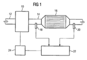
- a schematically illustrated internal combustion engine 10 sucks air via an intake tract 12 in the direction of the arrow.
- the leaked from the internal combustion engine 10 air is via an exhaust tract 14 in passed a three-way catalyst 16.
- a first oxygen probe 18 is provided, whose output signal depends continuously on the air ratio lambda in the exhaust gas flow.
- the oxygen sensors are also referred to as lambda probes.
- a second lambda probe 20 is arranged, which can check the catalyst efficiency and be designed as a linear probe or a so-called jump probe.
- the signals of the lambda probes 18 and 20 are forwarded to a lambda control device 22, which closes from the two signals supplied to the efficiency of the catalyst 16 and thus to the conversion of the exhaust gases.
- the lambda control device determines a desired lambda value as a manipulated variable and forwards it to the motor controller 24. Furthermore, the lambda control device may have a model for the behavior of the control path.
- the model includes, as a model parameter, the sensor delay time.
- the transfer function of the lambda control path has a behavior such as the series connection of two delay elements of the first order and a dead time element.
- the frequency and amplitude are determined as a function of the rotational speed and load and the operating temperature of the internal combustion engine.
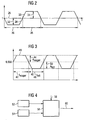
- FIG. 2 shows the lambda desired value over time.
- the desired lambda value fluctuates around the mean value 26 at which stoichiometric combustion takes place.
- the forcible excitation can be divided into a rich part 28 and a lean part 30.
- the amplitudes 32 and 34 of the respective excitation are the same size.
- the lean and the rich half wave 28 and 30 have the same duration 36 and 38, respectively.
- the Lambda setpoint is set here to 0.998 in order to reduce the risk of NOx breakthroughs.
- the positive excitation according to the invention has a lean half-wave 40, with a duration t lean 42 and an amplitude A lean 44.
- the lean half-wave 40 is followed by a rich half-wave 46.
- the fat half-wave 46 has a duration t fat 48 and an amplitude A fat 50.
- the four parameters characterizing the forcible excitation: t lean , A lean , t bold , A fat can be selected independently of each other.
- a first map 52 determines the values for a first frequency and a first amplitude depending on speed and load.
- the frequency is defined as an inverse period, wherein the period is the period of a defined exhaust gas packet sequence of lean and rich exhaust gas packets, which regularly repeats at steady-state operating conditions (ie with the same amount of exhaust gas per time and same exhaust gas composition). Under lean / fat amplitude, the lambda values of individual exhaust packets of the exhaust packet sequence are understood.
- the map 52 determines frequency and amplitude for a first temperature T 1 .
- the map 54 determines the values for a second frequency and a second amplitude depending on speed and load.
- the tuples of frequency and amplitude are forwarded to a calculation unit 56.
- the calculation unit 56 determines the tuple of setpoint values for frequency and amplitude 60 as a function of the actual value 58 for the operating temperature by means of a linear or a non-linear interpolation.
- the calculation manner shown in Fig. 4 can also be replaced by a three-dimensional map.
- the limit value with which the change of the model parameter is selected in a preferred embodiment also depends on the operating temperature. In addition, the limit may depend on the speed and load of the engine.
- a square wave or a sinusoidal oscillation can be used. It is also possible to provide a forced excitation with a sawtooth-shaped oscillation or another excitation pattern.
- the saw-toothed oscillation is characterized by amplitude, frequency and rise time. Also, the rise time can be selected in the inventive method depending on the operating temperature.
Landscapes
- Engineering & Computer Science (AREA)
- Chemical & Material Sciences (AREA)
- Combustion & Propulsion (AREA)
- Mechanical Engineering (AREA)
- General Engineering & Computer Science (AREA)
- Electrical Control Of Air Or Fuel Supplied To Internal-Combustion Engine (AREA)
- Exhaust Gas After Treatment (AREA)
Claims (6)
- Procédé pour l'excitation forcée d'une régulation lambda dans un moteur à combustion interne, qui comprend les étapes de procédé suivantes :- à une valeur de consigne de lambda, on superpose une excitation forcée possédant au moins une fréquence et une amplitude et qui possède un segment pauvre et un segment riche,- les valeurs pour l'amplitude et/ou la fréquence de l'excitation forcée sont déterminées en fonction d'une température de fonctionnement du moteur à combustion interne.
- Procédé selon la revendication 1, caractérisé en ce que les valeurs pour l'amplitude et/ou la fréquence de l'excitation forcée sont déterminées en fonction de la température de fonctionnement de l'eau de refroidissement.
- Procédé selon la revendication 1 ou 2, caractérisé en ce que les valeurs pour l'amplitude et/ou la fréquence de l'excitation forcée sont déterminées en outre en fonction de la température de fonctionnement de la culasse.
- Procédé selon une des revendications 1 à 3, caractérisé en ce que les valeurs pour l'amplitude et/ou la fréquence de l'excitation forcée sont déterminées en outre en fonction de la température de fonctionnement de l'huile.
- Procédé selon une des revendications 1 à 4, caractérisé en ce que les valeurs pour l'amplitude et/ou la fréquence de l'excitation forcée sont déterminées en fonction de la masse d'air et de la vitesse de rotation à des températures prédéterminées.
- Procédé selon la revendication 5, caractérisé en ce qu'un premier diagramme (52) détermine des premières valeurs de consigne pour la fréquence et l'amplitude, en fonction de la charge et de la vitesse de rotation pour une première température, et un deuxième diagramme (54) détermine des deuxièmes valeurs de consigne pour la fréquence et l'amplitude, en fonction de la charge et de la vitesse de rotation pour une deuxième température, et un dispositif comparateur (56) interpole ou extrapole les valeurs de consigne en fonction de la température de fonctionnement (58) pour la température de fonctionnement présente.
Applications Claiming Priority (2)
| Application Number | Priority Date | Filing Date | Title |
|---|---|---|---|
| DE2002106675 DE10206675C1 (de) | 2002-02-18 | 2002-02-18 | Verfahren zur Zwangsanregung bei einer Lambdaregelug |
| DE10206675 | 2002-02-18 |
Publications (3)
| Publication Number | Publication Date |
|---|---|
| EP1336742A2 EP1336742A2 (fr) | 2003-08-20 |
| EP1336742A3 EP1336742A3 (fr) | 2006-03-15 |
| EP1336742B1 true EP1336742B1 (fr) | 2006-12-20 |
Family
ID=7713850
Family Applications (1)
| Application Number | Title | Priority Date | Filing Date |
|---|---|---|---|
| EP20030002339 Expired - Lifetime EP1336742B1 (fr) | 2002-02-18 | 2003-02-03 | Méthode pour stimuler une boucle de régulation lambda |
Country Status (2)
| Country | Link |
|---|---|
| EP (1) | EP1336742B1 (fr) |
| DE (2) | DE10206675C1 (fr) |
Families Citing this family (5)
| Publication number | Priority date | Publication date | Assignee | Title |
|---|---|---|---|---|
| WO2004085819A1 (fr) | 2003-03-26 | 2004-10-07 | Mitsubishi Jidosha Kogyo Kabushiki Kaisha | Dispositif de regulation des emissions d'echappement d'un moteur a combustion interne |
| DE10358900A1 (de) * | 2003-12-16 | 2005-07-21 | Volkswagen Ag | Verfahren zum Betreiben einer Brennkraftmaschine mit kontinuierlicher Lambda-Regelung |
| DE102004038481B3 (de) * | 2004-08-07 | 2005-07-07 | Audi Ag | Verfahren zur Regelung des einer Brennkraftmaschine zugeführten Luft/Kraftstoffverhältnisses |
| US7793489B2 (en) * | 2005-06-03 | 2010-09-14 | Gm Global Technology Operations, Inc. | Fuel control for robust detection of catalytic converter oxygen storage capacity |
| DE102021120527A1 (de) | 2021-08-06 | 2023-02-09 | Ford Global Technologies, Llc | Verfahren zum Steuern einer gasbetriebenen Brennkraftmaschine |
Family Cites Families (4)
| Publication number | Priority date | Publication date | Assignee | Title |
|---|---|---|---|---|
| US5325664A (en) * | 1991-10-18 | 1994-07-05 | Honda Giken Kogyo Kabushiki Kaisha | System for determining deterioration of catalysts of internal combustion engines |
| JP3162524B2 (ja) * | 1992-12-29 | 2001-05-08 | 本田技研工業株式会社 | 内燃機関の空燃比制御装置 |
| DE19744410C2 (de) * | 1997-10-08 | 2001-06-21 | Ford Global Tech Inc | Verfahren zur Überwachung der Laufruheregelung eines Verbrennungsmotors |
| DE19844994C2 (de) * | 1998-09-30 | 2002-01-17 | Siemens Ag | Verfahren zur Diagnose einer stetigen Lambdasonde |
-
2002
- 2002-02-18 DE DE2002106675 patent/DE10206675C1/de not_active Expired - Fee Related
-
2003
- 2003-02-03 EP EP20030002339 patent/EP1336742B1/fr not_active Expired - Lifetime
- 2003-02-03 DE DE50306001T patent/DE50306001D1/de not_active Expired - Lifetime
Also Published As
| Publication number | Publication date |
|---|---|
| EP1336742A3 (fr) | 2006-03-15 |
| DE10206675C1 (de) | 2003-05-22 |
| DE50306001D1 (de) | 2007-02-01 |
| EP1336742A2 (fr) | 2003-08-20 |
Similar Documents
| Publication | Publication Date | Title |
|---|---|---|
| EP1024254B1 (fr) | Procédé et dispositif de commande d' un système de post-traitement des gaz d'échappement | |
| DE10051150C2 (de) | Regelung des Luft/Kraftstoff-Verhältnisses in einem Motor | |
| DE60029893T2 (de) | Luft-Kraftstoffverhältnissteuerapparat für multizylindrigen Verbrennungsmotor | |
| DE10224601B4 (de) | Verfahren und Steuereinrichtung zur Steuerung des Beriebes einer Brennkraftmaschine | |
| DE112007000322B4 (de) | Abgassystem für eine Brennkraftmaschine | |
| DE3700401A1 (de) | Gemischregelvorrichtung fuer einen magermotor | |
| DE19839791B4 (de) | Luft-Brennstoffverhältnisregelung für eine Brennkraftmaschine | |
| DE60025893T2 (de) | Steuerungsvorrichtung für das Kraftstoff-Luftverhältnis in einer mehrzylindrigen Brennkraftmaschine | |
| DE112012006716T5 (de) | Steuervorrichtung für Verbrennungsmotor | |
| DE19851843B4 (de) | Verfahren zur Sulfatregeneration eines NOx-Speicherkatalysators für eine Mager-Brennkraftmaschine | |
| EP1193376B1 (fr) | Commande d'un catalyseur accumulateur de nox | |
| DE4215787C2 (de) | Luft/Brennstoff-Verhältnis-Steuerungsgerät für eine Brennkraftmaschine | |
| EP1336742B1 (fr) | Méthode pour stimuler une boucle de régulation lambda | |
| DE19935968B4 (de) | Steuereinheit für das Luft-/Kraftstoffverhältnis eines Motors | |
| DE19926146A1 (de) | Verfahren zur Initiierung und Überwachung einer Entschwefelung von wenigstens einem in einem Abgaskanal einer Verbrennungskraftmaschine angeordneten NOx-Speicherkatalysator | |
| DE19912832B4 (de) | Vorrichtung zur Steuerung des Luft-Kraftstoff-Verhältnisses für einen Verbrennungsmotor | |
| DE3540420C2 (fr) | ||
| EP1255922B1 (fr) | Dispositif et procede pour commander le mode de fonctionnement d'un moteur multicylindre pour vehicules automobiles comprenant une installation de purification des gaz d'echappement a plusieurs flux | |
| DE69606533T2 (de) | Modulation des luft-brennstoff verhältnisses | |
| DE112014006704T5 (de) | Abgasreinigungssystem für einen Verbrennungsmotor | |
| DE69810019T2 (de) | Elektronische Vorrichtung zum Steuern des Luft-Kraftstoff-Verhältnisses des einem Verbrennungsmotor zugeführten Gasgemisches | |
| EP1143131A2 (fr) | Système d'échappement multiple et procédé pour la régulation du rapport air/carburant et pour le contrôle de la régénération d'un catalyseur d'accumulation des oxydes d'azote | |
| DE10148128A1 (de) | Verfahren und Vorrichtung zur Reduzierung einer Schadstoffendemission einer Verbrennungskraftmaschine | |
| EP1183454B1 (fr) | PROCEDE DE COMMANDE DE LA REGENERATION D'UN CATALYSEUR ACCUMULATEUR DE NOx | |
| DE19912833A1 (de) | Luft-Kraftstoff-Verhältnissteuerung für einen Verbrennungsmotor |
Legal Events
| Date | Code | Title | Description |
|---|---|---|---|
| PUAI | Public reference made under article 153(3) epc to a published international application that has entered the european phase |
Free format text: ORIGINAL CODE: 0009012 |
|
| AK | Designated contracting states |
Designated state(s): AT BE BG CH CY CZ DE DK EE ES FI FR GB GR HU IE IT LI LU MC NL PT SE SI SK TR |
|
| AX | Request for extension of the european patent |
Extension state: AL LT LV MK RO |
|
| PUAL | Search report despatched |
Free format text: ORIGINAL CODE: 0009013 |
|
| AK | Designated contracting states |
Kind code of ref document: A3 Designated state(s): AT BE BG CH CY CZ DE DK EE ES FI FR GB GR HU IE IT LI LU MC NL PT SE SI SK TR |
|
| AX | Request for extension of the european patent |
Extension state: AL LT LV MK RO |
|
| 17P | Request for examination filed |
Effective date: 20060206 |
|
| GRAP | Despatch of communication of intention to grant a patent |
Free format text: ORIGINAL CODE: EPIDOSNIGR1 |
|
| GRAS | Grant fee paid |
Free format text: ORIGINAL CODE: EPIDOSNIGR3 |
|
| GRAA | (expected) grant |
Free format text: ORIGINAL CODE: 0009210 |
|
| AKX | Designation fees paid |
Designated state(s): DE FR GB IT |
|
| AK | Designated contracting states |
Kind code of ref document: B1 Designated state(s): DE FR GB IT |
|
| REG | Reference to a national code |
Ref country code: GB Ref legal event code: FG4D Free format text: NOT ENGLISH |
|
| GBT | Gb: translation of ep patent filed (gb section 77(6)(a)/1977) |
Effective date: 20070110 |
|
| REF | Corresponds to: |
Ref document number: 50306001 Country of ref document: DE Date of ref document: 20070201 Kind code of ref document: P |
|
| ET | Fr: translation filed | ||
| PLBE | No opposition filed within time limit |
Free format text: ORIGINAL CODE: 0009261 |
|
| STAA | Information on the status of an ep patent application or granted ep patent |
Free format text: STATUS: NO OPPOSITION FILED WITHIN TIME LIMIT |
|
| 26N | No opposition filed |
Effective date: 20070921 |
|
| PGFP | Annual fee paid to national office [announced via postgrant information from national office to epo] |
Ref country code: GB Payment date: 20090219 Year of fee payment: 7 |
|
| PGFP | Annual fee paid to national office [announced via postgrant information from national office to epo] |
Ref country code: IT Payment date: 20090220 Year of fee payment: 7 |
|
| PGFP | Annual fee paid to national office [announced via postgrant information from national office to epo] |
Ref country code: FR Payment date: 20090213 Year of fee payment: 7 |
|
| GBPC | Gb: european patent ceased through non-payment of renewal fee |
Effective date: 20100203 |
|
| REG | Reference to a national code |
Ref country code: FR Ref legal event code: ST Effective date: 20101029 |
|
| PG25 | Lapsed in a contracting state [announced via postgrant information from national office to epo] |
Ref country code: FR Free format text: LAPSE BECAUSE OF NON-PAYMENT OF DUE FEES Effective date: 20100301 |
|
| PG25 | Lapsed in a contracting state [announced via postgrant information from national office to epo] |
Ref country code: GB Free format text: LAPSE BECAUSE OF NON-PAYMENT OF DUE FEES Effective date: 20100203 Ref country code: IT Free format text: LAPSE BECAUSE OF NON-PAYMENT OF DUE FEES Effective date: 20100203 |
|
| PGFP | Annual fee paid to national office [announced via postgrant information from national office to epo] |
Ref country code: DE Payment date: 20200229 Year of fee payment: 18 |
|
| REG | Reference to a national code |
Ref country code: DE Ref legal event code: R084 Ref document number: 50306001 Country of ref document: DE |
|
| REG | Reference to a national code |
Ref country code: DE Ref legal event code: R081 Ref document number: 50306001 Country of ref document: DE Owner name: VITESCO TECHNOLOGIES GMBH, DE Free format text: FORMER OWNER: CONTINENTAL AUTOMOTIVE GMBH, 30165 HANNOVER, DE |
|
| REG | Reference to a national code |
Ref country code: DE Ref legal event code: R119 Ref document number: 50306001 Country of ref document: DE |
|
| PG25 | Lapsed in a contracting state [announced via postgrant information from national office to epo] |
Ref country code: DE Free format text: LAPSE BECAUSE OF NON-PAYMENT OF DUE FEES Effective date: 20210901 |