EP1336742A2 - Méthode pour stimuler une boucle de régulation lambda - Google Patents
Méthode pour stimuler une boucle de régulation lambda Download PDFInfo
- Publication number
- EP1336742A2 EP1336742A2 EP03002339A EP03002339A EP1336742A2 EP 1336742 A2 EP1336742 A2 EP 1336742A2 EP 03002339 A EP03002339 A EP 03002339A EP 03002339 A EP03002339 A EP 03002339A EP 1336742 A2 EP1336742 A2 EP 1336742A2
- Authority
- EP
- European Patent Office
- Prior art keywords
- amplitude
- frequency
- operating temperature
- lambda
- values
- Prior art date
- Legal status (The legal status is an assumption and is not a legal conclusion. Google has not performed a legal analysis and makes no representation as to the accuracy of the status listed.)
- Granted
Links
- 238000000034 method Methods 0.000 title claims abstract description 18
- 230000004936 stimulating effect Effects 0.000 title 1
- 230000005284 excitation Effects 0.000 claims description 33
- 238000002485 combustion reaction Methods 0.000 claims description 10
- 239000000498 cooling water Substances 0.000 claims description 4
- 230000000638 stimulation Effects 0.000 abstract description 9
- 230000001419 dependent effect Effects 0.000 abstract description 4
- 239000002826 coolant Substances 0.000 abstract 1
- 239000007789 gas Substances 0.000 description 12
- 239000000523 sample Substances 0.000 description 11
- 239000003054 catalyst Substances 0.000 description 10
- 238000004364 calculation method Methods 0.000 description 4
- 238000006243 chemical reaction Methods 0.000 description 4
- QVGXLLKOCUKJST-UHFFFAOYSA-N atomic oxygen Chemical compound [O] QVGXLLKOCUKJST-UHFFFAOYSA-N 0.000 description 3
- 239000001301 oxygen Substances 0.000 description 3
- 229910052760 oxygen Inorganic materials 0.000 description 3
- 230000006978 adaptation Effects 0.000 description 2
- 230000003197 catalytic effect Effects 0.000 description 2
- 238000011144 upstream manufacturing Methods 0.000 description 2
- 230000003321 amplification Effects 0.000 description 1
- 230000002950 deficient Effects 0.000 description 1
- 230000001627 detrimental effect Effects 0.000 description 1
- 238000003745 diagnosis Methods 0.000 description 1
- 238000010586 diagram Methods 0.000 description 1
- 239000000446 fuel Substances 0.000 description 1
- 230000007257 malfunction Effects 0.000 description 1
- 238000003199 nucleic acid amplification method Methods 0.000 description 1
- 230000000737 periodic effect Effects 0.000 description 1
- 239000010970 precious metal Substances 0.000 description 1
Images

Classifications
-
- F—MECHANICAL ENGINEERING; LIGHTING; HEATING; WEAPONS; BLASTING
- F02—COMBUSTION ENGINES; HOT-GAS OR COMBUSTION-PRODUCT ENGINE PLANTS
- F02D—CONTROLLING COMBUSTION ENGINES
- F02D41/00—Electrical control of supply of combustible mixture or its constituents
- F02D41/02—Circuit arrangements for generating control signals
- F02D41/14—Introducing closed-loop corrections
- F02D41/1438—Introducing closed-loop corrections using means for determining characteristics of the combustion gases; Sensors therefor
- F02D41/1493—Details
- F02D41/1495—Detection of abnormalities in the air/fuel ratio feedback system
-
- F—MECHANICAL ENGINEERING; LIGHTING; HEATING; WEAPONS; BLASTING
- F02—COMBUSTION ENGINES; HOT-GAS OR COMBUSTION-PRODUCT ENGINE PLANTS
- F02D—CONTROLLING COMBUSTION ENGINES
- F02D41/00—Electrical control of supply of combustible mixture or its constituents
- F02D41/02—Circuit arrangements for generating control signals
- F02D41/14—Introducing closed-loop corrections
- F02D41/1401—Introducing closed-loop corrections characterised by the control or regulation method
- F02D41/1408—Dithering techniques
-
- F—MECHANICAL ENGINEERING; LIGHTING; HEATING; WEAPONS; BLASTING
- F02—COMBUSTION ENGINES; HOT-GAS OR COMBUSTION-PRODUCT ENGINE PLANTS
- F02D—CONTROLLING COMBUSTION ENGINES
- F02D41/00—Electrical control of supply of combustible mixture or its constituents
- F02D41/02—Circuit arrangements for generating control signals
- F02D41/14—Introducing closed-loop corrections
- F02D41/1438—Introducing closed-loop corrections using means for determining characteristics of the combustion gases; Sensors therefor
- F02D41/1439—Introducing closed-loop corrections using means for determining characteristics of the combustion gases; Sensors therefor characterised by the position of the sensor
- F02D41/1441—Plural sensors
Definitions
- the invention relates to a method for positive excitation Lambda control with which an error in a lambda probe is detected becomes.
- a Diagnosed Lambda probe located upstream of a catalyst.
- the lambda probe to be diagnosed has a constant characteristic in its output signal.
- the lambda probe becomes a periodic lambda setpoint Forced excitation with a given frequency and amplitude superimposed.
- a model of the lambda control loop forms its line behavior, with one of the model parameters represents the sensor delay time. From the amplifications of the amplitudes, which are for the model and system for forced excitation result, the model values, especially the model value adapted for the sensor delay time.
- the lambda sensor is recognized as defective if the value for the change in the model parameter has a predetermined threshold exceeds. This means that if you are too strong Adaptation of the sensor delay time is a malfunction of the Lambda sensor is recognized. This way it can be continuous the functioning of the lambda probe in the lambda control circuit be checked.
- the stoichiometric setpoint for the air ratio is subjected to a positive excitation.
- the deviation from the stoichiometric setpoint alternately have a lean and fat shift.
- the oxygen storage of the catalyst is filled, O 2 is stored, while the catalyst is emptied again during the fat shift.
- This filling and emptying process depends on the setpoint shift (amplitude of the forced excitation) and the duration of the shift. It is known to carry out the forced stimulation in a time-based approach with the same amplitude and the same duration for fat and lean stimulation.
- the invention has for its object a method for Forced excitation of a lambda probe in an internal combustion engine provide that is not detrimental to exhaust emissions affects and a good exhaust gas conversion over wide operating areas ensures.
- the values for amplitude are selected and frequency of the forced excitation depending on an operating temperature the internal combustion engine.
- This solution of the invention The task is based on the knowledge that the known forced excitation for some operating conditions to a leads to poor conversion of the exhaust gases.
- By amplitude and frequency of the forced excitation adapted to the operating temperature are, according to the invention, also in low load and Idling range and increased exhaust emission values after a cold start avoided.
- the values for amplitude preferably depend and / or frequency of the forced excitation from the operating temperature of the cooling water. So far it is common for the Amplitude and frequency of the forced excitation relate to a cooling water temperature from 85 ° C.
- the values for amplitude and / or frequency can also be dependent the temperature of the cylinder head and / or the oil temperature be determined for the forced excitation. Prefers In addition to the operating temperature, the air mass and the speed of predetermined temperature values is taken into account.
- the one from the internal combustion engine 10 leaked air is in through an exhaust tract 14 in a three-way catalyst 16 passed.
- a first oxygen probe 18 is provided for catalytic converter 16, whose output signal steadily depends on the air ratio lambda in the Exhaust gas flow depends.
- the oxygen sensors are also called Called lambda sensors.
- a second lambda probe 20 is arranged which measures the catalyst efficiency checked and as a linear probe or one so-called jump probe can be formed.
- the signals from the lambda probes 18 and 20 are sent to a lambda control device 22 forwarded from the two delivered signals on the efficiency of the catalyst 16 and thus concludes the conversion of the exhaust gases.
- the lambda control device determines a desired lambda value as a manipulated variable and passes this on to the engine control 24. Furthermore, the lambda control device can be a model for the behavior of the control system.
- the model includes, as a model parameter, the sensor delay time. As known from DE 195 16 239 C2, has the transfer function the lambda control system behaves like series connection two first order delay elements and a dead time link. To make as little change as possible to maintain the exhaust emission during the forced excitation Frequency and amplitude depending on speed and load as well the operating temperature of the internal combustion engine.
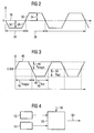
- the lambda setpoint fluctuates with the known forced excitation around the mean 26 at which stoichiometric combustion he follows.
- the forced excitation can be in a fat part 28 and a lean part 30 can be divided.
- the amplitudes 32 and 34 of each suggestion are the same size. Own as well the lean and the fat half-wave 28 and 30 respectively same duration 36 or 38.
- the lambda setpoint is set at 0.998 to reduce the risk of NOx breakthroughs.
- the forced excitation according to the invention has a lean half-wave 40 with a duration t lean 42 and an amplitude A lean 44.
- a fat half-wave 46 follows the lean half-wave 40.
- the bold half-wave 46 has a duration t bold 48 and an amplitude A bold 50.
- the four parameters characterizing the forced excitation: t lean , A lean , t rich , A rich can be selected independently of one another.
- a first characteristic map 52 determines the values for a first frequency and a first amplitude as a function of speed and load.
- the frequency is defined as an inverse period, the period being the time period of a defined exhaust gas sequence of lean and rich exhaust gas packages, which is repeated regularly under steady-state operating conditions (ie with the same amount of exhaust gas per time and the same exhaust gas composition).
- Lean / rich amplitude is understood to mean the lambda values of individual exhaust gas packets of the exhaust gas packet sequence.
- the map 52 determines the frequency and amplitude for a first temperature T 1 .
- the map 54 determines the values for a second frequency and a second amplitude depending on the speed and load.
- the tuples of frequency and amplitude are forwarded to a calculation unit 56.
- the calculation unit 56 determines the tuple of nominal values for frequency and amplitude 60 by means of a linear or a non-linear interpolation.
- the calculation method shown in FIG. 4 can also be carried out by a three-dimensional map can be replaced.
- the method according to the invention shows particular advantages operating temperature-dependent forced excitation also related in a so-called electronic thermal management, at which the operating temperature of the engine with the aim of a low fuel consumption and good exhaust gas values is varied.
- thermal management works through a targeted adaptation of the forced control to the operating temperature supported.
- the limit with which to change the model parameter selected in a preferred embodiment also depends on the operating temperature.
- the Limit value of the speed and the load of the internal combustion engine depend.
- a square wave or a sinusoidal vibration can be used. Is also it is possible to use excitation with a sawtooth To provide vibration or another excitation pattern.
- the sawtooth-shaped vibration is by amplitude, frequency and Marked rise time.
- the rise time can also be the inventive method depending on the operating temperature to get voted.
Landscapes
- Engineering & Computer Science (AREA)
- Chemical & Material Sciences (AREA)
- Combustion & Propulsion (AREA)
- Mechanical Engineering (AREA)
- General Engineering & Computer Science (AREA)
- Electrical Control Of Air Or Fuel Supplied To Internal-Combustion Engine (AREA)
- Exhaust Gas After Treatment (AREA)
Applications Claiming Priority (2)
| Application Number | Priority Date | Filing Date | Title |
|---|---|---|---|
| DE10206675 | 2002-02-18 | ||
| DE2002106675 DE10206675C1 (de) | 2002-02-18 | 2002-02-18 | Verfahren zur Zwangsanregung bei einer Lambdaregelug |
Publications (3)
| Publication Number | Publication Date |
|---|---|
| EP1336742A2 true EP1336742A2 (fr) | 2003-08-20 |
| EP1336742A3 EP1336742A3 (fr) | 2006-03-15 |
| EP1336742B1 EP1336742B1 (fr) | 2006-12-20 |
Family
ID=7713850
Family Applications (1)
| Application Number | Title | Priority Date | Filing Date |
|---|---|---|---|
| EP20030002339 Expired - Lifetime EP1336742B1 (fr) | 2002-02-18 | 2003-02-03 | Méthode pour stimuler une boucle de régulation lambda |
Country Status (2)
| Country | Link |
|---|---|
| EP (1) | EP1336742B1 (fr) |
| DE (2) | DE10206675C1 (fr) |
Families Citing this family (5)
| Publication number | Priority date | Publication date | Assignee | Title |
|---|---|---|---|---|
| US7275364B2 (en) | 2003-03-26 | 2007-10-02 | Mitsubishi Jidosha Kogyo Kabushiki Kaisha | Exhaust emission control device of internal combustion engine |
| DE10358900A1 (de) * | 2003-12-16 | 2005-07-21 | Volkswagen Ag | Verfahren zum Betreiben einer Brennkraftmaschine mit kontinuierlicher Lambda-Regelung |
| DE102004038481B3 (de) * | 2004-08-07 | 2005-07-07 | Audi Ag | Verfahren zur Regelung des einer Brennkraftmaschine zugeführten Luft/Kraftstoffverhältnisses |
| US7793489B2 (en) * | 2005-06-03 | 2010-09-14 | Gm Global Technology Operations, Inc. | Fuel control for robust detection of catalytic converter oxygen storage capacity |
| DE102021120527A1 (de) | 2021-08-06 | 2023-02-09 | Ford Global Technologies, Llc | Verfahren zum Steuern einer gasbetriebenen Brennkraftmaschine |
Citations (2)
| Publication number | Priority date | Publication date | Assignee | Title |
|---|---|---|---|---|
| DE4344892C2 (de) | 1992-12-29 | 1998-04-23 | Honda Motor Co Ltd | Luft-Kraftstoff-Verhältnissteuereinrichtung für eine Brennkraftmaschine |
| DE19844994A1 (de) | 1998-09-30 | 2000-04-06 | Siemens Ag | Verfahren zur Diagnose einer stetigen Lambdasonde |
Family Cites Families (2)
| Publication number | Priority date | Publication date | Assignee | Title |
|---|---|---|---|---|
| US5325664A (en) * | 1991-10-18 | 1994-07-05 | Honda Giken Kogyo Kabushiki Kaisha | System for determining deterioration of catalysts of internal combustion engines |
| DE19744410C2 (de) * | 1997-10-08 | 2001-06-21 | Ford Global Tech Inc | Verfahren zur Überwachung der Laufruheregelung eines Verbrennungsmotors |
-
2002
- 2002-02-18 DE DE2002106675 patent/DE10206675C1/de not_active Expired - Fee Related
-
2003
- 2003-02-03 EP EP20030002339 patent/EP1336742B1/fr not_active Expired - Lifetime
- 2003-02-03 DE DE50306001T patent/DE50306001D1/de not_active Expired - Lifetime
Patent Citations (2)
| Publication number | Priority date | Publication date | Assignee | Title |
|---|---|---|---|---|
| DE4344892C2 (de) | 1992-12-29 | 1998-04-23 | Honda Motor Co Ltd | Luft-Kraftstoff-Verhältnissteuereinrichtung für eine Brennkraftmaschine |
| DE19844994A1 (de) | 1998-09-30 | 2000-04-06 | Siemens Ag | Verfahren zur Diagnose einer stetigen Lambdasonde |
Also Published As
| Publication number | Publication date |
|---|---|
| DE10206675C1 (de) | 2003-05-22 |
| EP1336742B1 (fr) | 2006-12-20 |
| DE50306001D1 (de) | 2007-02-01 |
| EP1336742A3 (fr) | 2006-03-15 |
Similar Documents
| Publication | Publication Date | Title |
|---|---|---|
| EP1024254B1 (fr) | Procédé et dispositif de commande d' un système de post-traitement des gaz d'échappement | |
| DE112007000322B4 (de) | Abgassystem für eine Brennkraftmaschine | |
| DE69202163T2 (de) | Abgasentgiftungsanlage für eine Brennkraftmaschine. | |
| DE10022981B4 (de) | Schadstoffbegrenzungssystem | |
| DE102007025377B4 (de) | Luft/Kraftstoff-Verhältnis-Steuervorrichtung für einen Verbrennungsmotor | |
| DE60029893T2 (de) | Luft-Kraftstoffverhältnissteuerapparat für multizylindrigen Verbrennungsmotor | |
| DE19953601A1 (de) | Verfahren zum Überprüfen eines Abgaskatalysators einer Brennkraftmaschine | |
| DE19539024C2 (de) | Diagnoseeinrichtung zur Erfassung von Katalysatorschäden eines in der Abgasleitung einer Brennkraftmaschine angeordneten Katalysators | |
| DE19839791B4 (de) | Luft-Brennstoffverhältnisregelung für eine Brennkraftmaschine | |
| DE4219134A1 (de) | Luft/brennstoff-verhaeltnis-steuerungsgeraet fuer eine maschine | |
| DE112012006716T5 (de) | Steuervorrichtung für Verbrennungsmotor | |
| DE19545924B4 (de) | Verfahren und Vorrichtungen zum Steuern des Luft/Kraftstoffverhältnis-Lernens eines Motors mit innerer Verbrennung | |
| DE19851843B4 (de) | Verfahren zur Sulfatregeneration eines NOx-Speicherkatalysators für eine Mager-Brennkraftmaschine | |
| DE3821357A1 (de) | Verfahren und vorrichtung zur lambdaregelung mit mehreren sonden | |
| DE19926146A1 (de) | Verfahren zur Initiierung und Überwachung einer Entschwefelung von wenigstens einem in einem Abgaskanal einer Verbrennungskraftmaschine angeordneten NOx-Speicherkatalysator | |
| EP1336742B1 (fr) | Méthode pour stimuler une boucle de régulation lambda | |
| DE19935968B4 (de) | Steuereinheit für das Luft-/Kraftstoffverhältnis eines Motors | |
| DE3540420C2 (fr) | ||
| DE69606533T2 (de) | Modulation des luft-brennstoff verhältnisses | |
| DE102018133185A1 (de) | Abgasreinigungsvorrichtung für einen verbrennungsmotor | |
| DE102018133184A1 (de) | Abgasreinigungsvorrichtung für einen verbrennungsmotor | |
| EP1255922B1 (fr) | Dispositif et procede pour commander le mode de fonctionnement d'un moteur multicylindre pour vehicules automobiles comprenant une installation de purification des gaz d'echappement a plusieurs flux | |
| DE10023072B4 (de) | Verfahren sowie Vorrichtung zur Bestimmung einer NOx-Konzentration eines Abgasstromes einer Verbrennungskraftmaschine | |
| DE69810019T2 (de) | Elektronische Vorrichtung zum Steuern des Luft-Kraftstoff-Verhältnisses des einem Verbrennungsmotor zugeführten Gasgemisches | |
| DE19958468C2 (de) | Diagnoseverfahren für eine Brennkraftmaschine sowie Vorrichtung zur Durchführung des Verfahrens |
Legal Events
| Date | Code | Title | Description |
|---|---|---|---|
| PUAI | Public reference made under article 153(3) epc to a published international application that has entered the european phase |
Free format text: ORIGINAL CODE: 0009012 |
|
| AK | Designated contracting states |
Designated state(s): AT BE BG CH CY CZ DE DK EE ES FI FR GB GR HU IE IT LI LU MC NL PT SE SI SK TR |
|
| AX | Request for extension of the european patent |
Extension state: AL LT LV MK RO |
|
| PUAL | Search report despatched |
Free format text: ORIGINAL CODE: 0009013 |
|
| AK | Designated contracting states |
Kind code of ref document: A3 Designated state(s): AT BE BG CH CY CZ DE DK EE ES FI FR GB GR HU IE IT LI LU MC NL PT SE SI SK TR |
|
| AX | Request for extension of the european patent |
Extension state: AL LT LV MK RO |
|
| 17P | Request for examination filed |
Effective date: 20060206 |
|
| GRAP | Despatch of communication of intention to grant a patent |
Free format text: ORIGINAL CODE: EPIDOSNIGR1 |
|
| GRAS | Grant fee paid |
Free format text: ORIGINAL CODE: EPIDOSNIGR3 |
|
| GRAA | (expected) grant |
Free format text: ORIGINAL CODE: 0009210 |
|
| AKX | Designation fees paid |
Designated state(s): DE FR GB IT |
|
| AK | Designated contracting states |
Kind code of ref document: B1 Designated state(s): DE FR GB IT |
|
| REG | Reference to a national code |
Ref country code: GB Ref legal event code: FG4D Free format text: NOT ENGLISH |
|
| GBT | Gb: translation of ep patent filed (gb section 77(6)(a)/1977) |
Effective date: 20070110 |
|
| REF | Corresponds to: |
Ref document number: 50306001 Country of ref document: DE Date of ref document: 20070201 Kind code of ref document: P |
|
| ET | Fr: translation filed | ||
| PLBE | No opposition filed within time limit |
Free format text: ORIGINAL CODE: 0009261 |
|
| STAA | Information on the status of an ep patent application or granted ep patent |
Free format text: STATUS: NO OPPOSITION FILED WITHIN TIME LIMIT |
|
| 26N | No opposition filed |
Effective date: 20070921 |
|
| PGFP | Annual fee paid to national office [announced via postgrant information from national office to epo] |
Ref country code: GB Payment date: 20090219 Year of fee payment: 7 |
|
| PGFP | Annual fee paid to national office [announced via postgrant information from national office to epo] |
Ref country code: IT Payment date: 20090220 Year of fee payment: 7 |
|
| PGFP | Annual fee paid to national office [announced via postgrant information from national office to epo] |
Ref country code: FR Payment date: 20090213 Year of fee payment: 7 |
|
| GBPC | Gb: european patent ceased through non-payment of renewal fee |
Effective date: 20100203 |
|
| REG | Reference to a national code |
Ref country code: FR Ref legal event code: ST Effective date: 20101029 |
|
| PG25 | Lapsed in a contracting state [announced via postgrant information from national office to epo] |
Ref country code: FR Free format text: LAPSE BECAUSE OF NON-PAYMENT OF DUE FEES Effective date: 20100301 |
|
| PG25 | Lapsed in a contracting state [announced via postgrant information from national office to epo] |
Ref country code: GB Free format text: LAPSE BECAUSE OF NON-PAYMENT OF DUE FEES Effective date: 20100203 Ref country code: IT Free format text: LAPSE BECAUSE OF NON-PAYMENT OF DUE FEES Effective date: 20100203 |
|
| PGFP | Annual fee paid to national office [announced via postgrant information from national office to epo] |
Ref country code: DE Payment date: 20200229 Year of fee payment: 18 |
|
| REG | Reference to a national code |
Ref country code: DE Ref legal event code: R084 Ref document number: 50306001 Country of ref document: DE |
|
| REG | Reference to a national code |
Ref country code: DE Ref legal event code: R081 Ref document number: 50306001 Country of ref document: DE Owner name: VITESCO TECHNOLOGIES GMBH, DE Free format text: FORMER OWNER: CONTINENTAL AUTOMOTIVE GMBH, 30165 HANNOVER, DE |
|
| REG | Reference to a national code |
Ref country code: DE Ref legal event code: R119 Ref document number: 50306001 Country of ref document: DE |
|
| PG25 | Lapsed in a contracting state [announced via postgrant information from national office to epo] |
Ref country code: DE Free format text: LAPSE BECAUSE OF NON-PAYMENT OF DUE FEES Effective date: 20210901 |