EP1336748B1 - Luftzufuhrsystem für eine Brennkraftmaschine - Google Patents
Luftzufuhrsystem für eine Brennkraftmaschine Download PDFInfo
- Publication number
- EP1336748B1 EP1336748B1 EP03250901A EP03250901A EP1336748B1 EP 1336748 B1 EP1336748 B1 EP 1336748B1 EP 03250901 A EP03250901 A EP 03250901A EP 03250901 A EP03250901 A EP 03250901A EP 1336748 B1 EP1336748 B1 EP 1336748B1
- Authority
- EP
- European Patent Office
- Prior art keywords
- combustion air
- collecting container
- engine
- air
- supply arrangement
- Prior art date
- Legal status (The legal status is an assumption and is not a legal conclusion. Google has not performed a legal analysis and makes no representation as to the accuracy of the status listed.)
- Expired - Lifetime
Links
- 238000002485 combustion reaction Methods 0.000 claims abstract description 69
- 239000012530 fluid Substances 0.000 claims abstract description 17
- XLYOFNOQVPJJNP-UHFFFAOYSA-N water Substances O XLYOFNOQVPJJNP-UHFFFAOYSA-N 0.000 claims description 40
- 238000004891 communication Methods 0.000 claims description 6
- 238000001816 cooling Methods 0.000 claims description 5
- 239000007788 liquid Substances 0.000 claims description 4
- 238000010438 heat treatment Methods 0.000 claims description 3
- MWUXSHHQAYIFBG-UHFFFAOYSA-N nitrogen oxide Inorganic materials O=[N] MWUXSHHQAYIFBG-UHFFFAOYSA-N 0.000 description 14
- 238000010276 construction Methods 0.000 description 5
- 239000007789 gas Substances 0.000 description 4
- 239000000498 cooling water Substances 0.000 description 3
- 238000000926 separation method Methods 0.000 description 3
- 230000000694 effects Effects 0.000 description 2
- 230000001627 detrimental effect Effects 0.000 description 1
- 230000003467 diminishing effect Effects 0.000 description 1
- 238000002347 injection Methods 0.000 description 1
- 239000007924 injection Substances 0.000 description 1
- 238000004519 manufacturing process Methods 0.000 description 1
- 238000000034 method Methods 0.000 description 1
- 239000000203 mixture Substances 0.000 description 1
- 238000012986 modification Methods 0.000 description 1
- 230000004048 modification Effects 0.000 description 1
- 230000002035 prolonged effect Effects 0.000 description 1
- 238000004064 recycling Methods 0.000 description 1
Images
Classifications
-
- F—MECHANICAL ENGINEERING; LIGHTING; HEATING; WEAPONS; BLASTING
- F02—COMBUSTION ENGINES; HOT-GAS OR COMBUSTION-PRODUCT ENGINE PLANTS
- F02M—SUPPLYING COMBUSTION ENGINES IN GENERAL WITH COMBUSTIBLE MIXTURES OR CONSTITUENTS THEREOF
- F02M35/00—Combustion-air cleaners, air intakes, intake silencers, or induction systems specially adapted for, or arranged on, internal-combustion engines
- F02M35/02—Air cleaners
- F02M35/08—Air cleaners with means for removing dust, particles or liquids from cleaners; with means for indicating clogging; with by-pass means; Regeneration of cleaners
- F02M35/088—Water, snow or ice proofing; Separation or drainage of water, snow or ice
-
- F—MECHANICAL ENGINEERING; LIGHTING; HEATING; WEAPONS; BLASTING
- F02—COMBUSTION ENGINES; HOT-GAS OR COMBUSTION-PRODUCT ENGINE PLANTS
- F02M—SUPPLYING COMBUSTION ENGINES IN GENERAL WITH COMBUSTIBLE MIXTURES OR CONSTITUENTS THEREOF
- F02M25/00—Engine-pertinent apparatus for adding non-fuel substances or small quantities of secondary fuel to combustion-air, main fuel or fuel-air mixture
- F02M25/022—Adding fuel and water emulsion, water or steam
- F02M25/025—Adding water
- F02M25/028—Adding water into the charge intakes
-
- F—MECHANICAL ENGINEERING; LIGHTING; HEATING; WEAPONS; BLASTING
- F02—COMBUSTION ENGINES; HOT-GAS OR COMBUSTION-PRODUCT ENGINE PLANTS
- F02B—INTERNAL-COMBUSTION PISTON ENGINES; COMBUSTION ENGINES IN GENERAL
- F02B2275/00—Other engines, components or details, not provided for in other groups of this subclass
- F02B2275/34—Lateral camshaft position
-
- Y—GENERAL TAGGING OF NEW TECHNOLOGICAL DEVELOPMENTS; GENERAL TAGGING OF CROSS-SECTIONAL TECHNOLOGIES SPANNING OVER SEVERAL SECTIONS OF THE IPC; TECHNICAL SUBJECTS COVERED BY FORMER USPC CROSS-REFERENCE ART COLLECTIONS [XRACs] AND DIGESTS
- Y02—TECHNOLOGIES OR APPLICATIONS FOR MITIGATION OR ADAPTATION AGAINST CLIMATE CHANGE
- Y02T—CLIMATE CHANGE MITIGATION TECHNOLOGIES RELATED TO TRANSPORTATION
- Y02T10/00—Road transport of goods or passengers
- Y02T10/10—Internal combustion engine [ICE] based vehicles
- Y02T10/12—Improving ICE efficiencies
Definitions
- This invention relates to an air feeding arrangement for a piston engine comprising a feed channel for feeding combustion air into the engine, a collecting container, to which the feed channel is connected, feed pipes for feeding combustion air from the collecting chamber to each engine cylinder, and means for introducing moistening fluid into the combustion air.
- the invention also relates to a piston engine provided with such an air feeding arrangement.
- nitrogen oxides are produced in cylinders of piston engines and are entrained in exhaust gases which pass into the air. Due to the detrimental effects of nitrogen oxide emissions on the environment it is desirable to minimise such emissions.
- An object of the present invention is to provide an air supply arrangement in which the problems of the prior art is minimised.
- the present invention seeks to provide an air supply arrangement in which the humidification of the combustion air is performed advantageously and effectively.
- an air supply arrangement for a piston engine comprising a feed channel for feeding combustion air into the engine, a collecting container to which said feed channel is connected, a separate feed pipe for feeding combustion air from the collecting chamber to the or each engine cylinder, and means for introducing moistening fluid into the combustion air, is characterised in that at least one droplet separator is arranged after the collecting container in the flow direction of the combustion air.
- a separate droplet separator is preferably arranged in each feed pipe to separate liquid moistening fluid from the combustion air.
- the means for introducing moistening fluid into the combustion air comprise a water tank or the like, with which the combustion air collecting container is in flow communication, e.g. via a return duct for separated water.
- a convenient and reliable construction is achieved by providing at least one connecting piece for connecting the collecting container to a cylinder head of the engine.
- the or each droplet separator is easy to maintain or replace.
- the or each droplet separator is associated with a joint member of the or the associated connecting piece.
- the means for introducing moistening fluid into the combustion air comprises at least one nozzle for introducing moistening fluid into the combustion air after a turbocharger and before the collecting container.
- the arrangement may comprise at least one heat exchanger for heating or cooling the combustion air.
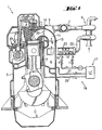
- a piston engine according to the invention is designated by the reference numeral 1.
- the engine comprises an engine block 2, a cylinder 3 and a cylinder head 4.
- the engine comprises a plurality of cylinders each of which may have a cylinder head of its own.
- the engine also includes an exhaust manifold 7 connected to a turbocharger 8.
- the engine comprises a collecting container 6 for combustion air, arranged in the engine block 2 and into which the turbocharger 8 is arranged to feed combustion air.
- Each cylinder 3 of the engine is provided with a connecting piece 5 for various pressure mediums, by means of which connecting piece it is possible to arrange, for example, the cooling circulation of the cylinder head and the gas exchange of the cylinder.
- Such arrangements may be realised as shown, for instance, in US-A-5,213,068.
- the connecting piece 5 has a feed pipe 11 for conducting combustion air from the collecting container 6 of the engine block 2 to the cylinder 3 via the cylinder head 4.
- the feed pipe 11 for combustion air is shown in hatched lines in Fig. 2 with the flow direction being shown by arrow A.
- the connecting piece 5 also has an exhaust gas channel 12 for conducting exhaust gases from the cylinder 3 via the cylinder head 4 to the exhaust pipe 7.
- the connecting piece 5 may include a cooling water channel 13 for recycling cooling water for the cylinder 3 via the cylinder head 4 and to a collecting channel for cooling water in the engine block 2.
- the connecting piece 5 is provided with joint members 14 and 15 for connecting to corresponding joint members of the cylinder head 4 and the engine block 2, respectively.
- the turbocharger 8 is in connection with the collecting container 6 via a feed pipe or channel 22 for combustion air, usually at the other end of the container 6.
- Means 16 are also provided for introducing moistening fluid into the combustion air.
- the feed channel 22 for combustion air is provided with nozzles 18, 19 for injecting water into the combustion air.
- one or several heat exchangers 23 is or are installed in the feed channel for either heating or cooling the combustion air as the situation requires. Combustion air is conducted from the collecting container 6 to each cylinder. Therefore the arrangement comprises a separate feed channel 11 for combustion air for each cylinder arranged in the joint member 15, the channel 11 being in connection with the collecting container 6 for combustion air.
- each feed pipe 11 for combustion air is provided with a droplet separator 20 for separating moistening fluid in liquid form from the combustion air.
- Each droplet separator 20 may be arranged so that the separated water flows down to the collecting container 6 for combustion air.
- the collecting container 6 is in flow communication with the means 17 for introducing moistening fluid into the combustion air.
- This flow connection is provided to recirculate the separated water and to re-inject it into the combustion air.
- the means 17 for introducing moistening fluid into the combustion air comprise a water tank or the like 17', with which the collecting container 6 is in flow communication.
- the air supply arrangement comprises a return duct 21 for separated water forming the flow connection between the collecting container 6 and the water tank or the like 17'.
- the droplet separator 20 may also be arranged so that the separated water flows down via a separate channel 25 to the water tank or the like 17'.
- the assembly may comprise either a return duct 21 connecting the collecting container 6 and the water tank or the like 17', or a separate channel 25 connecting the droplet separator 20 and the water tank or the like 17'.
- the engine may also be provided with both channels at the same time, e.g. in a case where the amount of water to be separated is very large.
- the arrangement is made particularly advantageous, if the droplet separator 20 is arranged in conjunction with the connecting piece 5 which connects the cylinder head 4 of the engine and the collecting container 6, whereby the fastening thereof is simple and reliable.
- the air supply arrangement according to the invention provides an efficient air treatment and humidification process, as water can be utilised more freely than in conventional arrangements and the separation of the used water as a liquid is efficient.
- the channel 22 for combustion air is typically located at one end of the collecting container 6 and water is injected into the combustion air before the collecting container 6, whereby the dwell time of the water in the combustion air before the water separation is prolonged. Also with this arrangement the increase of air humidity is more efficient. There may constantly be a predetermined amount of water in the collecting container, some of which is also vaporised into the combustion air.
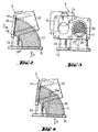
- Fig. 2 shows in more detail the connecting piece 5 connecting the cylinder head 4 of the engine and the collecting container 6.
- a recess 24 having a larger diameter than the flow passage is arranged for the droplet separators 20 in conjunction with a flange that is used as a joint member of the connecting piece 5 so that the droplet separator 20 is located between the flange of the connecting piece and the joint surface of the cylinder head 4.
- a groove 24' or an equivalent channel may be arranged to extend from the recess 24 to one of the joint surfaces 15 of the connecting piece for securing the flow of the separated water to the collecting container 6 so that air flowing to the cylinder does not substantially hamper or disturb the return of the water.
- Fig. 3 shows the connecting piece 5 of Fig. 2 seen from the direction of arrow D.
- the droplet separator 20 extends to an area that is wider than the flow area, and thus it fills the recess hole 24.
- this kind of a construction is used when the aim is to conduct the separated water into the collecting container 6.
- the engine comprises a separate channel 25, as described above, the channel 25 is connected to the droplet separator 20 instead of the groove 24'.
- Fig. 4 shows another possible location for a droplet separator 20 associated with the connecting piece.
- the droplet separator is associated with one of the joint surfaces 15 of the connecting piece 5.
- a recess 24a i.e. a groove or the like, at a certain angle relative to the surface 15, in which groove the droplet separator 20 can be installed by inserting it into the feed pipe 11 for combustion air.
- the groove supports the droplet separator and holds it in place. In this manner the area of the droplet separator can be made larger than in the case shown in Fig. 2 thus diminishing its flow resistance.
- the droplet separator has such a construction that it takes its position when the connecting piece 5 is fixed on the collecting container for the combustion air of the engine.
- the main advantage is the reduction of nitrogen oxide emissions.
Landscapes
- Engineering & Computer Science (AREA)
- Chemical & Material Sciences (AREA)
- Combustion & Propulsion (AREA)
- Mechanical Engineering (AREA)
- General Engineering & Computer Science (AREA)
- Exhaust Gas After Treatment (AREA)
- Cylinder Crankcases Of Internal Combustion Engines (AREA)
- Lubrication Details And Ventilation Of Internal Combustion Engines (AREA)
- Compressors, Vaccum Pumps And Other Relevant Systems (AREA)
- Exhaust-Gas Circulating Devices (AREA)
- Fuel-Injection Apparatus (AREA)
- Valve Device For Special Equipments (AREA)
- Valves And Accessory Devices For Braking Systems (AREA)
Claims (10)
- Luftversorgungsanordnung für einen Kolbenmotor (1) mit einem Zufuhrkanal (22) zur Zuführung von Verbrennungsluft in den Motor, einem Sammelbehälter (6), mit dem der Zufuhrkanal (22) verbunden ist, einem getrennten Zufuhrrohr (11) zur Zuführung von Verbrennungsluft aus der Sammelkammer (6) zu dem oder jedem Zylinder (3) und Mitteln (17) zur Einleitung von Befeuchtungsfluid in die Verbrennungsluft,
dadurch gekennzeichnet, dass
mindestens ein Tropfenabscheider (20) in Strömungsrichtung der Verbrennungsluft hinter dem Sammelbehälter (6) angeordnet ist. - Luftversorgungsanordnung nach Anspruch 1, dadurch gekennzeichnet, dass mehrere Zufuhrrohre vorgesehen sind und ein getrennter Tropfenabscheider (20) in jedem Zufuhrrohr (11) zur Trennung von flüssigem Befeuchtungsfluid von der Verbrennungsluft angeordnet ist.
- Luftversorgungsanordnung nach Anspruch 2, dadurch gekennzeichnet, dass die Mittel (17) zur Einleitung von Befeuchtungsfluid in die Verbrennungsluft Wassertankmittel (17') umfassen und dass der Sammelbehälter (6) für Verbrennungsluft über einen Rückführkanal (21) für getrenntes Wasser mit den Wassertankmitteln (17') in Strömungsverbindung steht.
- Luftversorgungsanordnung nach Anspruch 2, dadurch gekennzeichnet, dass die Mittel (17) zur Einleitung von Befeuchtungsfluid in die Verbrennungsluft Wassertankmittel (17') umfassen und dass jeder Tropfenabscheider (20) mit den Wassertankmitteln (17') in Strömungsverbindung steht.
- Luftversorgungsanordnung nach Anspruch 3, dadurch gekennzeichnet, dass jeder Tropfenabscheider über einen Rückführkanal (25) für getrenntes Wasser mit den Wassertankmitteln (17') in Strömungsverbindung steht.
- Luftversorgungsanordnung nach einem der vorhergehenden Ansprüche, dadurch gekennzeichnet, dass der oder jeder Tropfenabscheider (20) in einem einen Zylinderkopf (4) des Motors und den Sammelbehälter (6) verbindenden Verbindungsstück (5) angebracht ist.
- Luftversorgungsanordnung nach Anspruch 6, dadurch gekennzeichnet, dass der oder jeder Tropfenabscheider (20) unter Verwendung von Verbindungsgliedern (14, 15) des Verbindungsstücks (5) angebracht ist.
- Luftversorgungsanordnung nach einem der vorhergehenden Ansprüche, dadurch gekennzeichnet, dass das Mittel (17) zur Einleitung von Befeuchtungsfluid in die Verbrennungsluft mindestens eine Düse (18, 19) umfasst und dass die mindestens eine Düse (18, 19) zur Einleitung von Befeuchtungsfluid in die Verbrennungsluft hinter einem Turbolader (8) und vor dem Sammelbehälter (6) angeordnet ist.
- Luftversorgungsanordnung nach einem der vorhergehenden Ansprüche, dadurch gekennzeichnet, dass sie mindestens einen Wärmetauscher (23) zum Erwärmen oder Kühlen der Verbrennungsluft enthält.
- Kolbenmotor, der mit einer Luftzufuhranordnung nach einem der vorhergehenden Ansprüche versehen ist.
Applications Claiming Priority (2)
| Application Number | Priority Date | Filing Date | Title |
|---|---|---|---|
| FI20020309 | 2002-02-15 | ||
| FI20020309A FI114333B (fi) | 2002-02-15 | 2002-02-15 | Mäntämoottorin ilmansyöttöjärjestely |
Publications (3)
| Publication Number | Publication Date |
|---|---|
| EP1336748A2 EP1336748A2 (de) | 2003-08-20 |
| EP1336748A3 EP1336748A3 (de) | 2004-01-02 |
| EP1336748B1 true EP1336748B1 (de) | 2005-05-04 |
Family
ID=8563226
Family Applications (1)
| Application Number | Title | Priority Date | Filing Date |
|---|---|---|---|
| EP03250901A Expired - Lifetime EP1336748B1 (de) | 2002-02-15 | 2003-02-13 | Luftzufuhrsystem für eine Brennkraftmaschine |
Country Status (5)
| Country | Link |
|---|---|
| EP (1) | EP1336748B1 (de) |
| JP (1) | JP2003247464A (de) |
| AT (1) | ATE294923T1 (de) |
| DE (1) | DE60300583T2 (de) |
| FI (1) | FI114333B (de) |
Cited By (1)
| Publication number | Priority date | Publication date | Assignee | Title |
|---|---|---|---|---|
| CN108869119A (zh) * | 2018-06-01 | 2018-11-23 | 中国煤炭科工集团太原研究院有限公司 | 撞击窒息节能式火焰熄灭装置及控制方法 |
Families Citing this family (3)
| Publication number | Priority date | Publication date | Assignee | Title |
|---|---|---|---|---|
| JP4614134B2 (ja) * | 2005-12-16 | 2011-01-19 | トヨタ自動車株式会社 | 過給機付内燃機関 |
| CN101078384B (zh) * | 2007-07-06 | 2012-12-26 | 靳宇男 | 汽冲压式内外燃发动机 |
| KR101886756B1 (ko) * | 2016-11-23 | 2018-08-10 | 한국기술교육대학교 산학협력단 | 터보차저의 압축흡기 냉각시스템 |
Family Cites Families (3)
| Publication number | Priority date | Publication date | Assignee | Title |
|---|---|---|---|---|
| DK170217B1 (da) * | 1993-06-04 | 1995-06-26 | Man B & W Diesel Gmbh | Stor trykladet forbrændingsmotor og fremgangsmåde til drift af en køler til afkøling af en sådan motors indsugningsluft. |
| US6196165B1 (en) * | 1998-11-12 | 2001-03-06 | Munters Euroform Gmbh | Device for supplying vapor to the intake air of an internal combustion engine |
| FI112692B (fi) * | 2000-11-03 | 2003-12-31 | Waertsilae Finland Oy | Menetelmä ja järjestely ahdetun mäntämoottorin typpioksidipäästöjen (NOx) vähentämiseksi |
-
2002
- 2002-02-15 FI FI20020309A patent/FI114333B/fi active IP Right Grant
-
2003
- 2003-02-13 DE DE60300583T patent/DE60300583T2/de not_active Expired - Fee Related
- 2003-02-13 EP EP03250901A patent/EP1336748B1/de not_active Expired - Lifetime
- 2003-02-13 AT AT03250901T patent/ATE294923T1/de not_active IP Right Cessation
- 2003-02-14 JP JP2003035894A patent/JP2003247464A/ja active Pending
Cited By (2)
| Publication number | Priority date | Publication date | Assignee | Title |
|---|---|---|---|---|
| CN108869119A (zh) * | 2018-06-01 | 2018-11-23 | 中国煤炭科工集团太原研究院有限公司 | 撞击窒息节能式火焰熄灭装置及控制方法 |
| CN108869119B (zh) * | 2018-06-01 | 2021-02-02 | 中国煤炭科工集团太原研究院有限公司 | 撞击窒息节能式火焰熄灭装置及控制方法 |
Also Published As
| Publication number | Publication date |
|---|---|
| JP2003247464A (ja) | 2003-09-05 |
| DE60300583T2 (de) | 2006-02-23 |
| EP1336748A2 (de) | 2003-08-20 |
| FI114333B (fi) | 2004-09-30 |
| ATE294923T1 (de) | 2005-05-15 |
| FI20020309A0 (fi) | 2002-02-15 |
| DE60300583D1 (de) | 2005-06-09 |
| EP1336748A3 (de) | 2004-01-02 |
| FI20020309A7 (fi) | 2003-08-16 |
Similar Documents
| Publication | Publication Date | Title |
|---|---|---|
| CN100365265C (zh) | 大型增压内燃发动机 | |
| EP0736684B1 (de) | Einlasskrümmer für Brennkraftmaschine | |
| US5791304A (en) | Cylinder wall fuel injection system for cross-scavenged, two-cycle combustion engine | |
| CN102713231B (zh) | 用于再循环的废气与空气的混合管 | |
| FI114112B (fi) | Menetelmä polttomoottorin pakokaasujen puhdistamiseksi ja laitteisto kostean ilman syöttämiseksi polttomoottoriin | |
| US20040244734A1 (en) | Arrangement and method in connection with diesel engine | |
| FI116157B (fi) | Menetelmä ahdetun mäntämoottorin typpioksidipäästöjen (NOx) vähentämiseksi ja mäntämoottorijärjestely | |
| US6912978B2 (en) | Air feeding arrangement for piston engine | |
| US6196165B1 (en) | Device for supplying vapor to the intake air of an internal combustion engine | |
| CN109891068A (zh) | 包括布置在涡轮上游的还原剂供应系统的多管排气系统 | |
| EP1336748B1 (de) | Luftzufuhrsystem für eine Brennkraftmaschine | |
| CN101876286A (zh) | 发动机燃料汽化管理系统 | |
| US10054072B2 (en) | Exhaust gas recirculation system for an internal combustion engine | |
| US7926472B2 (en) | Inlet system | |
| JP2010090717A (ja) | 内燃機関における排気ガス還流装置 | |
| EP1680590B1 (de) | Verfahren zur reduzierung von stickoxidemissionen (nox) eines aufgeladenen kolbenmotors und kolbenmotoranordnung | |
| JP2012112297A (ja) | 内燃機関の吸気装置 | |
| US7096829B2 (en) | Spraying head | |
| CN100480503C (zh) | 内燃发动机、气缸盖及制造方法和燃料供应系统 | |
| KR20220093372A (ko) | 편향기를 가진 실린더 헤드의 흡기구의 탈유 가스 흡기 장치 | |
| JPH0650216A (ja) | V型エンジンのegr通路構造 | |
| JP2604294Y2 (ja) | 吸気マニホールド | |
| JP2022143035A (ja) | エンジンの吸気マニホールド | |
| JPH0749062A (ja) | 内燃機関のnox 低減システム | |
| HK1059810B (en) | Method and apparatus for reducing combustion engine emissions |
Legal Events
| Date | Code | Title | Description |
|---|---|---|---|
| PUAI | Public reference made under article 153(3) epc to a published international application that has entered the european phase |
Free format text: ORIGINAL CODE: 0009012 |
|
| AK | Designated contracting states |
Designated state(s): AT BE BG CH CY CZ DE DK EE ES FI FR GB GR HU IE IT LI LU MC NL PT SE SI SK TR |
|
| AX | Request for extension of the european patent |
Extension state: AL LT LV MK RO |
|
| PUAL | Search report despatched |
Free format text: ORIGINAL CODE: 0009013 |
|
| AK | Designated contracting states |
Kind code of ref document: A3 Designated state(s): AT BE BG CH CY CZ DE DK EE ES FI FR GB GR HU IE IT LI LU MC NL PT SE SI SK TR |
|
| AX | Request for extension of the european patent |
Extension state: AL LT LV MK RO |
|
| RIC1 | Information provided on ipc code assigned before grant |
Ipc: 7F 02B 47/02 B Ipc: 7F 02B 29/04 B Ipc: 7F 02M 25/02 B Ipc: 7F 02M 25/028 A |
|
| RAP1 | Party data changed (applicant data changed or rights of an application transferred) |
Owner name: WAERTSILAE FINLAND OY |
|
| GRAP | Despatch of communication of intention to grant a patent |
Free format text: ORIGINAL CODE: EPIDOSNIGR1 |
|
| 17P | Request for examination filed |
Effective date: 20040622 |
|
| AKX | Designation fees paid |
Designated state(s): AT BE BG CH CY CZ DE DK EE ES FI FR GB GR HU IE IT LI LU MC NL PT SE SI SK TR |
|
| GRAS | Grant fee paid |
Free format text: ORIGINAL CODE: EPIDOSNIGR3 |
|
| GRAA | (expected) grant |
Free format text: ORIGINAL CODE: 0009210 |
|
| RIN1 | Information on inventor provided before grant (corrected) |
Inventor name: ROESGREN, CARL-ERIK Inventor name: RAIKIO, TERO |
|
| AK | Designated contracting states |
Kind code of ref document: B1 Designated state(s): AT BE BG CH CY CZ DE DK EE ES FI FR GB GR HU IE IT LI LU MC NL PT SE SI SK TR |
|
| PG25 | Lapsed in a contracting state [announced via postgrant information from national office to epo] |
Ref country code: NL Free format text: LAPSE BECAUSE OF FAILURE TO SUBMIT A TRANSLATION OF THE DESCRIPTION OR TO PAY THE FEE WITHIN THE PRESCRIBED TIME-LIMIT Effective date: 20050504 Ref country code: BE Free format text: LAPSE BECAUSE OF FAILURE TO SUBMIT A TRANSLATION OF THE DESCRIPTION OR TO PAY THE FEE WITHIN THE PRESCRIBED TIME-LIMIT Effective date: 20050504 Ref country code: FI Free format text: LAPSE BECAUSE OF FAILURE TO SUBMIT A TRANSLATION OF THE DESCRIPTION OR TO PAY THE FEE WITHIN THE PRESCRIBED TIME-LIMIT Effective date: 20050504 Ref country code: SK Free format text: LAPSE BECAUSE OF FAILURE TO SUBMIT A TRANSLATION OF THE DESCRIPTION OR TO PAY THE FEE WITHIN THE PRESCRIBED TIME-LIMIT Effective date: 20050504 Ref country code: CZ Free format text: LAPSE BECAUSE OF FAILURE TO SUBMIT A TRANSLATION OF THE DESCRIPTION OR TO PAY THE FEE WITHIN THE PRESCRIBED TIME-LIMIT Effective date: 20050504 Ref country code: SI Free format text: LAPSE BECAUSE OF FAILURE TO SUBMIT A TRANSLATION OF THE DESCRIPTION OR TO PAY THE FEE WITHIN THE PRESCRIBED TIME-LIMIT Effective date: 20050504 |
|
| REG | Reference to a national code |
Ref country code: GB Ref legal event code: FG4D |
|
| RIC1 | Information provided on ipc code assigned before grant |
Ipc: 7F 02B 47/02 B Ipc: 7F 02B 29/04 B Ipc: 7F 02M 25/028 A |
|
| REG | Reference to a national code |
Ref country code: CH Ref legal event code: EP |
|
| REG | Reference to a national code |
Ref country code: IE Ref legal event code: FG4D |
|
| REF | Corresponds to: |
Ref document number: 60300583 Country of ref document: DE Date of ref document: 20050609 Kind code of ref document: P |
|
| REG | Reference to a national code |
Ref country code: CH Ref legal event code: NV Representative=s name: DR. R.C. SALGO + PARTNER PATENTANWAELTE AG |
|
| PG25 | Lapsed in a contracting state [announced via postgrant information from national office to epo] |
Ref country code: BG Free format text: LAPSE BECAUSE OF FAILURE TO SUBMIT A TRANSLATION OF THE DESCRIPTION OR TO PAY THE FEE WITHIN THE PRESCRIBED TIME-LIMIT Effective date: 20050804 Ref country code: DK Free format text: LAPSE BECAUSE OF FAILURE TO SUBMIT A TRANSLATION OF THE DESCRIPTION OR TO PAY THE FEE WITHIN THE PRESCRIBED TIME-LIMIT Effective date: 20050804 Ref country code: GR Free format text: LAPSE BECAUSE OF FAILURE TO SUBMIT A TRANSLATION OF THE DESCRIPTION OR TO PAY THE FEE WITHIN THE PRESCRIBED TIME-LIMIT Effective date: 20050804 Ref country code: SE Free format text: LAPSE BECAUSE OF FAILURE TO SUBMIT A TRANSLATION OF THE DESCRIPTION OR TO PAY THE FEE WITHIN THE PRESCRIBED TIME-LIMIT Effective date: 20050804 |
|
| PG25 | Lapsed in a contracting state [announced via postgrant information from national office to epo] |
Ref country code: ES Free format text: LAPSE BECAUSE OF FAILURE TO SUBMIT A TRANSLATION OF THE DESCRIPTION OR TO PAY THE FEE WITHIN THE PRESCRIBED TIME-LIMIT Effective date: 20050815 |
|
| PG25 | Lapsed in a contracting state [announced via postgrant information from national office to epo] |
Ref country code: PT Free format text: LAPSE BECAUSE OF FAILURE TO SUBMIT A TRANSLATION OF THE DESCRIPTION OR TO PAY THE FEE WITHIN THE PRESCRIBED TIME-LIMIT Effective date: 20051017 |
|
| NLV1 | Nl: lapsed or annulled due to failure to fulfill the requirements of art. 29p and 29m of the patents act | ||
| PG25 | Lapsed in a contracting state [announced via postgrant information from national office to epo] |
Ref country code: HU Free format text: LAPSE BECAUSE OF FAILURE TO SUBMIT A TRANSLATION OF THE DESCRIPTION OR TO PAY THE FEE WITHIN THE PRESCRIBED TIME-LIMIT Effective date: 20051105 |
|
| PG25 | Lapsed in a contracting state [announced via postgrant information from national office to epo] |
Ref country code: IE Free format text: LAPSE BECAUSE OF NON-PAYMENT OF DUE FEES Effective date: 20060213 |
|
| PG25 | Lapsed in a contracting state [announced via postgrant information from national office to epo] |
Ref country code: LU Free format text: LAPSE BECAUSE OF NON-PAYMENT OF DUE FEES Effective date: 20060228 Ref country code: MC Free format text: LAPSE BECAUSE OF NON-PAYMENT OF DUE FEES Effective date: 20060228 |
|
| PLBE | No opposition filed within time limit |
Free format text: ORIGINAL CODE: 0009261 |
|
| STAA | Information on the status of an ep patent application or granted ep patent |
Free format text: STATUS: NO OPPOSITION FILED WITHIN TIME LIMIT |
|
| 26N | No opposition filed |
Effective date: 20060207 |
|
| EN | Fr: translation not filed | ||
| REG | Reference to a national code |
Ref country code: IE Ref legal event code: MM4A |
|
| PG25 | Lapsed in a contracting state [announced via postgrant information from national office to epo] |
Ref country code: EE Free format text: LAPSE BECAUSE OF FAILURE TO SUBMIT A TRANSLATION OF THE DESCRIPTION OR TO PAY THE FEE WITHIN THE PRESCRIBED TIME-LIMIT Effective date: 20050504 |
|
| PG25 | Lapsed in a contracting state [announced via postgrant information from national office to epo] |
Ref country code: TR Free format text: LAPSE BECAUSE OF FAILURE TO SUBMIT A TRANSLATION OF THE DESCRIPTION OR TO PAY THE FEE WITHIN THE PRESCRIBED TIME-LIMIT Effective date: 20050504 |
|
| PG25 | Lapsed in a contracting state [announced via postgrant information from national office to epo] |
Ref country code: FR Free format text: LAPSE BECAUSE OF FAILURE TO SUBMIT A TRANSLATION OF THE DESCRIPTION OR TO PAY THE FEE WITHIN THE PRESCRIBED TIME-LIMIT Effective date: 20050504 Ref country code: CY Free format text: LAPSE BECAUSE OF FAILURE TO SUBMIT A TRANSLATION OF THE DESCRIPTION OR TO PAY THE FEE WITHIN THE PRESCRIBED TIME-LIMIT Effective date: 20050504 |
|
| PGFP | Annual fee paid to national office [announced via postgrant information from national office to epo] |
Ref country code: AT Payment date: 20090218 Year of fee payment: 7 |
|
| PGFP | Annual fee paid to national office [announced via postgrant information from national office to epo] |
Ref country code: DE Payment date: 20090219 Year of fee payment: 7 |
|
| PGFP | Annual fee paid to national office [announced via postgrant information from national office to epo] |
Ref country code: CH Payment date: 20090217 Year of fee payment: 7 Ref country code: GB Payment date: 20090219 Year of fee payment: 7 |
|
| PGFP | Annual fee paid to national office [announced via postgrant information from national office to epo] |
Ref country code: IT Payment date: 20090226 Year of fee payment: 7 |
|
| REG | Reference to a national code |
Ref country code: CH Ref legal event code: PL |
|
| GBPC | Gb: european patent ceased through non-payment of renewal fee |
Effective date: 20100213 |
|
| PG25 | Lapsed in a contracting state [announced via postgrant information from national office to epo] |
Ref country code: LI Free format text: LAPSE BECAUSE OF NON-PAYMENT OF DUE FEES Effective date: 20100228 Ref country code: CH Free format text: LAPSE BECAUSE OF NON-PAYMENT OF DUE FEES Effective date: 20100228 |
|
| PG25 | Lapsed in a contracting state [announced via postgrant information from national office to epo] |
Ref country code: AT Free format text: LAPSE BECAUSE OF NON-PAYMENT OF DUE FEES Effective date: 20100213 |
|
| PG25 | Lapsed in a contracting state [announced via postgrant information from national office to epo] |
Ref country code: DE Free format text: LAPSE BECAUSE OF NON-PAYMENT OF DUE FEES Effective date: 20100901 |
|
| PG25 | Lapsed in a contracting state [announced via postgrant information from national office to epo] |
Ref country code: GB Free format text: LAPSE BECAUSE OF NON-PAYMENT OF DUE FEES Effective date: 20100213 Ref country code: IT Free format text: LAPSE BECAUSE OF NON-PAYMENT OF DUE FEES Effective date: 20100213 |