EP1336767A2 - Dispositif de couplage pour bras pourvu d'un porte-outil de construction modulaire - Google Patents
Dispositif de couplage pour bras pourvu d'un porte-outil de construction modulaire Download PDFInfo
- Publication number
- EP1336767A2 EP1336767A2 EP03003134A EP03003134A EP1336767A2 EP 1336767 A2 EP1336767 A2 EP 1336767A2 EP 03003134 A EP03003134 A EP 03003134A EP 03003134 A EP03003134 A EP 03003134A EP 1336767 A2 EP1336767 A2 EP 1336767A2
- Authority
- EP
- European Patent Office
- Prior art keywords
- coupling
- power transmission
- transmission area
- shaft
- driver blocks
- Prior art date
- Legal status (The legal status is an assumption and is not a legal conclusion. Google has not performed a legal analysis and makes no representation as to the accuracy of the status listed.)
- Granted
Links
Images


Classifications
-
- B—PERFORMING OPERATIONS; TRANSPORTING
- B23—MACHINE TOOLS; METAL-WORKING NOT OTHERWISE PROVIDED FOR
- B23Q—DETAILS, COMPONENTS, OR ACCESSORIES FOR MACHINE TOOLS, e.g. ARRANGEMENTS FOR COPYING OR CONTROLLING; MACHINE TOOLS IN GENERAL CHARACTERISED BY THE CONSTRUCTION OF PARTICULAR DETAILS OR COMPONENTS; COMBINATIONS OR ASSOCIATIONS OF METAL-WORKING MACHINES, NOT DIRECTED TO A PARTICULAR RESULT
- B23Q3/00—Devices holding, supporting, or positioning work or tools, of a kind normally removable from the machine
-
- B—PERFORMING OPERATIONS; TRANSPORTING
- B23—MACHINE TOOLS; METAL-WORKING NOT OTHERWISE PROVIDED FOR
- B23B—TURNING; BORING
- B23B31/00—Chucks; Expansion mandrels; Adaptations thereof for remote control
- B23B31/02—Chucks
- B23B31/10—Chucks characterised by the retaining or gripping devices or their immediate operating means
- B23B31/117—Retention by friction only, e.g. using springs, resilient sleeves, tapers
-
- F—MECHANICAL ENGINEERING; LIGHTING; HEATING; WEAPONS; BLASTING
- F16—ENGINEERING ELEMENTS AND UNITS; GENERAL MEASURES FOR PRODUCING AND MAINTAINING EFFECTIVE FUNCTIONING OF MACHINES OR INSTALLATIONS; THERMAL INSULATION IN GENERAL
- F16D—COUPLINGS FOR TRANSMITTING ROTATION; CLUTCHES; BRAKES
- F16D1/00—Couplings for rigidly connecting two coaxial shafts or other movable machine elements
- F16D1/10—Quick-acting couplings in which the parts are connected by simply bringing them together axially
- F16D1/108—Quick-acting couplings in which the parts are connected by simply bringing them together axially having retaining means rotating with the coupling and acting by interengaging parts, i.e. positive coupling
-
- B—PERFORMING OPERATIONS; TRANSPORTING
- B23—MACHINE TOOLS; METAL-WORKING NOT OTHERWISE PROVIDED FOR
- B23B—TURNING; BORING
- B23B2260/00—Details of constructional elements
- B23B2260/056—Differential screw threads
-
- Y—GENERAL TAGGING OF NEW TECHNOLOGICAL DEVELOPMENTS; GENERAL TAGGING OF CROSS-SECTIONAL TECHNOLOGIES SPANNING OVER SEVERAL SECTIONS OF THE IPC; TECHNICAL SUBJECTS COVERED BY FORMER USPC CROSS-REFERENCE ART COLLECTIONS [XRACs] AND DIGESTS
- Y10—TECHNICAL SUBJECTS COVERED BY FORMER USPC
- Y10T—TECHNICAL SUBJECTS COVERED BY FORMER US CLASSIFICATION
- Y10T279/00—Chucks or sockets
- Y10T279/17—Socket type
- Y10T279/17957—Friction grip
-
- Y—GENERAL TAGGING OF NEW TECHNOLOGICAL DEVELOPMENTS; GENERAL TAGGING OF CROSS-SECTIONAL TECHNOLOGIES SPANNING OVER SEVERAL SECTIONS OF THE IPC; TECHNICAL SUBJECTS COVERED BY FORMER USPC CROSS-REFERENCE ART COLLECTIONS [XRACs] AND DIGESTS
- Y10—TECHNICAL SUBJECTS COVERED BY FORMER USPC
- Y10T—TECHNICAL SUBJECTS COVERED BY FORMER US CLASSIFICATION
- Y10T403/00—Joints and connections
- Y10T403/70—Interfitted members
-
- Y—GENERAL TAGGING OF NEW TECHNOLOGICAL DEVELOPMENTS; GENERAL TAGGING OF CROSS-SECTIONAL TECHNOLOGIES SPANNING OVER SEVERAL SECTIONS OF THE IPC; TECHNICAL SUBJECTS COVERED BY FORMER USPC CROSS-REFERENCE ART COLLECTIONS [XRACs] AND DIGESTS
- Y10—TECHNICAL SUBJECTS COVERED BY FORMER USPC
- Y10T—TECHNICAL SUBJECTS COVERED BY FORMER US CLASSIFICATION
- Y10T409/00—Gear cutting, milling, or planing
- Y10T409/30—Milling
- Y10T409/309352—Cutter spindle or spindle support
- Y10T409/309408—Cutter spindle or spindle support with cutter holder
-
- Y—GENERAL TAGGING OF NEW TECHNOLOGICAL DEVELOPMENTS; GENERAL TAGGING OF CROSS-SECTIONAL TECHNOLOGIES SPANNING OVER SEVERAL SECTIONS OF THE IPC; TECHNICAL SUBJECTS COVERED BY FORMER USPC CROSS-REFERENCE ART COLLECTIONS [XRACs] AND DIGESTS
- Y10—TECHNICAL SUBJECTS COVERED BY FORMER USPC
- Y10T—TECHNICAL SUBJECTS COVERED BY FORMER US CLASSIFICATION
- Y10T409/00—Gear cutting, milling, or planing
- Y10T409/30—Milling
- Y10T409/30952—Milling with cutter holder
Definitions
- the invention relates to a clutch, in particular a high-load coupling, for modular tool holder arms according to the preamble of claim 1, and one equipped with the clutch according to the invention
- Tool holder arm and its individual modules in particular an insert tool carrier piece, an extension piece and a basic recording piece, as well as one with a corresponding Interface equipped machine tool.
- the tool holder arms of today's machine tools are usually modular to make it easy Configurability and short set-up times and thus one ensure economic operation.
- Such a The tool holder arm can, for example, the individual modules Tool holder or insert tool carrier head (e.g. Drill chucks, milling holders, chucks for collets, Drill heads etc.), extension or intermediate piece (e.g. Boring bars, HSK basic shanks, chuck holders, Arbors etc.) and basic receptacle (SK receptacles, VDI holder, reducers, etc.).
- tool carrier head e.g. Drill chucks, milling holders, chucks for collets, Drill heads etc.
- extension or intermediate piece e.g. Boring bars, HSK basic shanks, chuck holders, Arbors etc.
- basic receptacle SK receptacles, VDI holder, reducers, etc.
- Clutches are usually used for power transmission frictionally by a central pin and a corresponding receptacle formed shaft-hub press fit (Steep taper systems, HSK systems, shrink chucks), positively over radially eccentrically arranged Driver stones, which are in corresponding recesses intervene of the respective counterpart or also form and non-positively via central pins and corresponding Recordings that have a profile, for example a Polygonal profile.
- Driving rings used, both on both sides have driver stones as well as central pins and two corresponding coupling sections with each other connect or hollow shaft taper systems (VDI holders) that in addition to a tapered shaft-hub seat Have driver stones.
- VDI holders hollow shaft taper systems
- the object of the present invention is therefore a Coupling for modular tool holder arms, as well one equipped with the clutch according to the invention
- Tool holder arm and its individual modules in particular an insert tool carrier piece, an extension or Intermediate piece and a corresponding basic receiving piece, and also a machine tool with a to create the appropriate interface in terms of of the above requirements are optimized and economical to manufacture with the simplest possible structure are.
- the coupling consists of a male coupling section with a central pin and a female Coupling section with a central receptacle that in each case the completion of a module of the tool arm form, for example the insert tool carrier piece and the basic recording.
- a first power transmission area namely a shaft-hub seat in Press fit, at least in a transition fit, in the transfer force positively or positively and non-positively becomes.
- the clutch still has at least another power transmission area in which additional power is transmitted. That way the total force that can be transmitted by the clutch increased.
- the power transmission in the power transmission areas leads to tension fields in the Material of the coupling sections, depending on the type and Characteristics of the power transmission areas are different Direction, strength and location and have different expansion or compression influences and again on the power transmission ability of the each affect other power transmission ranges can. Also a special shape of one of the power transmission areas can adversely affect power transmission ability the other power transmission areas impact, for example due to notches the notch effect. For these reasons, there may be interference come in power transmission when the tension fields of the individual power transmission areas by the respective other power transmission areas can be influenced.
- a voltage superposition avoided. This can not only avoid that different voltage components become one Add up total stress, which is the material resilience - at least in the long term (premature material fatigue) - exceeds, but also mutual interference of effectively suppressing at least two areas of tension on one another become. This is especially true for those through the Strain fields caused deformations, i.e. Strains / sprains. Also a negative influence a power transmission area through the shape another power transmission area is avoided. Overall, this not only makes it optimal and undisturbed power transmission on the at least two Power transmission areas (shaft-hub connection and further power transmission ranges) achieved, but at the same time also an improved concentricity of the entire tool holder arm.
- Such hollow cone systems have a high Bias on, for example, by biasing the by means of two nested coupling sections a differential screw can be done.
- the one in this Falling cone expansion due to the press fit on the taper / hollow taper shank is according to the invention through the at least one further power transmission area unaffected; the cone is widened therefore evenly over the entire circumference.
- cone expansion also affects power transmission the other power transmission areas not because the tension field of the other power transmission areas not superimposed and therefore their impact locally are limited.
- the Coupling a shaft-hub seat in polygon shape is not only by friction, but also by A load can be absorbed, so overall a higher load than with frictional engagement alone. Because it with such a profile too high stress concentrations at the rounded corners of the polygon comes in this case is a separation of the fields of tension particularly effective.
- the coupling is between the Modules of a tool holder arm provided, for example between an insert tool carrier head or a tool holder and a corresponding carrier head holder or spindle of the tool holder arm.
- the second power transmission area by two together adjacent flat surfaces formed.
- an HSK system Shaft-hub seat which has a high radial preload has the torsional transmission ability of Connection to one across the entire load spectrum limited constant value.
- Coupling can occur when high loads occur the torsional transmission capacity, so to speak, "if required" be increased.
- the separation of the tension fields is according to Claim 5 preferably by an axial distance of Power transmission area "shaft-hub-seat" from the power transmission area “Flat areas” reached. But it would be for example, differently pretreated surfaces of the shaft-hub seat in the area of the axial running surfaces compared to that of the area of the runways distant surfaces of the shaft-hub seat conceivable.
- This distance between the shaft-hub seat can be particularly simple and the adjacent flat surfaces according to claim 6 by a recess of the shaft-hub seat can be realized in the area of the run-flat areas.
- the recess is advantageous as a recess in the central recording of the female coupling part executed.
- a recess can also be made the pin of the male coupling part can be provided, whereby there are notch stress concentrations can come.
- the embodiment of the coupling according to claim 8 fixes the above problems through the Application of the principle of the invention, the separation of the Power transmission areas, on a coupling with off-center Drive keys.
- the separation of the power transmission areas Shaft-hub connection / drive blocks leads to the cone widening (or the radial preload) evenly over the circumference of the clamping cone or the shaft-hub press fit; the notch effect the driver stone grooves are omitted.
- a voltage overlay can be avoided under load.
- the separation of the power transmission areas is advantageously carried out Shaft-hub connection / drive blocks according to claim 9, characterized in that the driver blocks in one piece with one of the two coupling sections are provided.
- the conventional couplings with driving blocks Notch effect of screwing in the driver blocks intended grooves and their negative influence on the Voltage field of the shaft-hub seat and thus on the Avoid widening the cone.
- One in addition to Stress field occurring due to cone expansion There is a tension field as a result of an external load therefore no longer in the area of the cone / shaft-hub connection on the outer circumference of the recording.
- the load also occurs at the foot under load
- Driver stones i.e. where the driver blocks from the step out corresponding coupling section, a Notch effect on, so that through the driving stones caused stress field with that of the cone expansion in overlaid this area.
- the driver blocks axially spaced from the shaft-hub seat, to advantageously a negative Influence on the power transmission at the shaft-hub seat to avoid.
- the driver stones are preferred on the female Coupling section provided on the male coupling section the matching grooves, so that a notch effect through the to take the driving stones provided grooves is omitted. It is therefore a complete one Separation of the power transmission areas shaft-near-connection / drive keys; a voltage overlay does not take place and the cone widening takes place uniformly over the circumference and in axial Direction. This results in a significant increase in transferable torque, since only when the maximum friction torque loads the driver blocks become.
- the torsional moment that can be transmitted with the clutch to maximize further are in the preferred Embodiment in addition to the clamping cone both driver blocks as well as adjacent flat surfaces intended.
- the two power transmission areas Driver blocks / flat surfaces axially from the clamping cone spaced so that the bias of the cone and the resulting cone expansion is unaffected of the areas of tension between the driving blocks and the Flat butt joint evenly over the circumference and takes place in the axial direction.
- the recesses are the weakest points of the Are coupling section, they will be in response to the Taper expansion on the tensioning cone towards the inside loaded.
- the driver blocks become pulled inside (see Fig. 4b) and lie well against the Grooves of the mutual coupling section.
- the Power is thus transmitted to the driver blocks not only form-fitting on the radial surfaces of the Driver stones, but also frictionally on their Inner circumferential surfaces.
- the Stiffness of the clutch both advantageously in axially as well as in the radial direction.
- the frictional power transmission on the inner circumferential surfaces takes place increasingly on the axial End of the driver stones and decreases towards towards the recording.
- the power transmission range of the adjoining surfaces is therefore from the power transmission area the frictional engagement of the driver blocks Cut.
- One by the takeaway stones caused warping effect like a Disc spring on the flat surface of the female coupling section can be effectively suppressed and a good axial runout can be guaranteed.
- the recess can be in the form of an undercut with a gentle Diameter transition or a face milling of the receiving surface in the area of the driver blocks respectively:
- the invention is not based on the above Embodiments limited, in particular it is possible to provide any number of driver blocks, or the coupling sections each for in and to adapt counterparts executed according to foreign standards.
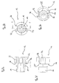
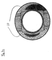
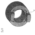
- FIGS. 3 show the two sections 12, 20 assembled coupling 10.
- the male coupling section 12 has one Pin 14, the female coupling section 20 a Recording 18 for the production of the tapered press fit 14, 18th on. 1, the grooves 32 for receiving the Driver stones 30 are removed, which in turn in 2 are shown. In the figures there is two also shown a turn designated 24, through which the inner cone of the face stop surface 22nd and the driver blocks 32 is spaced. On the The opposite side is the male coupling section Twist 25 through which the cone 14 from the flat surface 16 and the driving stone grooves 32 is spaced apart.
- the recess 24 forms and the twist 25 the separation of the power transmission area Cone press fit 14, 18 from the power transmission area Butt joint of the flat surfaces 16, 22 and the power transmission area on the driver blocks 30, which in Engagement with the driving stone grooves 32 are.
- suitable value for the distance 24, 25 between flat surfaces 16, 22 and shaft-hub seat 14, 18 has it a dimensioning of 0 - 1 times the nominal diameter proven the clutch.
- one Nominal diameter ⁇ 60mm of the coupling prefers a value selected from 14mm for the distance 24, 25.
- the female coupling part has one Milled 34 on the bottom of the driving stones 30 below their radially inner surface the plane of the plane surface 22 further into the receptacle 18 relocated into it.
- a rounded material transition 37 provided towards the plane surface 22 (cf. FIGS. 3a, 3d).
- the driving stone grooves 32 16 bevels 36 on the flat surface (cf. FIGS. 1, 3a, 3d).
- Figures 1 to 3 is also a central axial bore can be seen through the one differential screw can be guided to pretension the conical press fit.
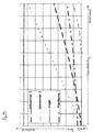
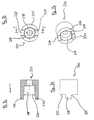
- Fig. 4a shows the distribution of the transmitted Torsional moment on the different power transmission areas:
- the torsional load on the flat surfaces 16, 22 is shown as a short-long dashed line, the torsional load on the first driving block 32 as dashed line with long lines, on the second driver block 32 as dashed twice short, once long Line.
- the constant over the entire load range Torsion transmission on the cone 14, 18, its Prestress corresponds to, is with a solid line shown.
- dashed Line with short lines the achievable torsion transmission with a driver of a conventional Driver ring with two drivers (DIN ring with two Drivers).
- the comparable sized DIN ring can on the other hand, only on each driver block Transfer torsional moment. It turned out that for Transmission of an equal total torsional moment Driver stones of the DIN ring are much more heavily loaded are used as the driver blocks in the invention Coupling, the torsion mount on the clamping cone remains constant and is thus protected against overload.
- the presented clutch can therefore also be essential withstand higher total loads than clutches with conventional DIN rings; i.e. by coupling the present preferred embodiment are torsional moments transfer that the previously tolerable limit torsional load exceed.
- Figures 4b, 4c and 4d each show that in the Simulation calculated stress fields 26, 27, 28 am Clamping cone 14, 18 (when the coupling is not loaded), the Surface pressure 16, 22 and on the more heavily loaded Driving block / driving block groove 30, 32nd direction of rotation is counterclockwise.
- Fig. 4b is on radial inner circumference with dashed line plotted a certain voltage potential located. Through the dash-dotted line is a second, higher voltage potential is shown. In Direction towards the driver blocks and the flat surface the stress caused by the cone pressure drops that is, until it joins the dotted line Falls below the limit. It can be clearly seen that this dashed border line is largely from the Driver stones and the flat surface runs spaced.
- FIG. 4c shows the simulation result of the Stress distribution on the flat surface.
- the 27 designated, dashed bordered areas higher Tension form the tension field at the butt joint of the Plane surfaces. It can be seen that this field of tension from Tension field 28 in the notch bottom of the higher stressed Driver stone (see Fig. 4d) on the in the direction of rotation lying side away.
- Fig. 4b it is also visible that the driver blocks due to the radial tension on the clamping cone inside as the cone is pulled through the press connection is expanded.
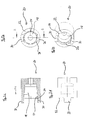
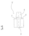
- FIGS. 5-7 Another preferred is shown in FIGS. 5-7 Embodiment of the present invention shown where no driver blocks are provided, but only the two power transmission areas shaft-hub connection and adjacent flat surfaces.
- the 5 shows the male coupling section 112, 6 shows the female coupling section 120 and 7 shows the two sections 112, 120 assembled coupling 100.
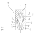
- the shaft-hub connection is a tension cone 114 and corresponding receptacle 118 executed. Between Flat surface 122 and the inner cone of the receptacle 118 there is a recess 124 ( Figures 6) between the flat surface 116 and the taper 114 is located a corresponding twist 125 ( Figures 5). All in all this results in the coupling 100 plugged together through the recess 124, 125 of the shaft-hub seat one Separation or decoupling of the power transmission area on the clamping cone 114 in the receptacle 118 and on the abutting plane surfaces 114, 118. Also here a central axial bore is provided through which one Screw to pretension the conical seat can.
- Figures 8-10 show a modified Embodiment of the invention.
- the male coupling component 212 is shown in Figures 8, the female Coupling component 220 in Figures 9 and the assembled Coupling 200 in FIGS. 10.
- the female component 220 has a conical shape Recording 218 for the pin 214 of the male component 212 on.
- a flat surface immediately adjoins the recording 222 on, when the coupling is connected the opposite plane surface 216 (see FIGS. 8a, 8b) is present.
- From the flat surface 222 of the female Coupling component 220 step two driver blocks 230 out.
- On the opposite side on the male coupling component 212 are correspondingly two driving stone grooves 232 intended.
- the separation of the power transmission areas tension cone and butt joint not by a turn in the Recording provided, but by a puncture or an undercut 224 (see FIGS. 8c, 8d and 10b), which on the male component, the pin 214 of separates the flat surface 16.
- the undercut 224 separates an annular material portion from the central pin 216 on a length determined axial length. at Composite coupling 200 can thus the pin under Load free along the entire length of the undercut 224 twist without warping each other adjacent plane surfaces 216, 222 occur.
- the female coupling part has one Milling 234 on (Fig. 9b, 9c), the notch base of the Driver blocks 30 below their radially inner Surface from the plane of the plane surface 222 further into the Receptacle 218 relocated and thus the power transmission area Driver blocks 230 and clamping cone 218 separates from each other.
- the notch base of the Driver blocks 30 below their radially inner Surface from the plane of the plane surface 222 further into the Receptacle 218 relocated and thus the power transmission area Driver blocks 230 and clamping cone 218 separates from each other.
- a rounded material transition 37 Fig. 9d
- the driving stone grooves point 232 corresponding roundings see Fig. 8d.
- the pin 212 in the receptacle 218 can be in the area twist the undercut 224 freely. additionally on the other hand, the radially inner notch base is the Driver blocks 230 on the one hand from the plane of the plane surface 222 relocated, on the other hand, it lies in scope the receptacle 218 spaced. So there is one here too Decoupling of the power transmission areas given, so that the occurring fields of tension do not or only little overlay.
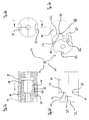
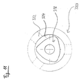
- FIG. 11 shows a female coupling component 320 a further embodiment of the invention with a polygonal receptacle 318 for receiving a corresponding pin of a coupling counterpart.
- the polygon profile of the recording is in an area 324 a depth of 0 - 1 times the nominal diameter between the ring-shaped plane surface 322 and the polygonal Shot 318 turned. That way when the coupling is assembled, the shaft-hub-seat in Area of the plane surface 322 recessed, which makes the two Power transmission areas of the polygonal shaft-hub seat and the butt joint on two abutting one another Plan areas are effectively separated.
- the admission has no driver stones.
- driver blocks would also be conceivable, especially in the dashed areas where the polygon profile of the Image taken farthest radially from the plane surface shrinks inside, so that a separation of the power transmission areas Driver blocks and shaft-hub seat could be realized particularly effectively.
- the due to the form fit on the polygonal shaft-hub seat occurring voltages in the area of the rounded Corners of the polygon profile would be from the Driving stones set so that it does not become one Overlay is coming.
- a smooth transfer of material from the inner diameter of the annular flat surface to Outside diameter of the polygon profile would be conceivable.
- Figures 12 and 13 show a last one Embodiment of the invention.
- Figure 12 is a male Coupling section with a pin. 414 shown, between the pin 414 and a this closing plane surface 416 a circumferential Notch 424 is located.
- Fig. 12 shows the assembled Coupling of this embodiment, one of which Cone 414 corresponding receptacle 418 provided which is surrounded by a flat surface 422.
- Out driver blocks 432 protrude from plane surface 422.
- Three power transmission areas are thus formed: Clamping cone 414, butt joint of the flat surfaces 416, 422 and Positive locking of the driver blocks 430 in the provided Grooves 432.
- a Warping of the plane surfaces becomes just as uneven Avoided cone expansion and the driving stones due to the radial expansion on the clamping cone inwards drawn.
- the invention thus consists of a clutch 10; 100; 200; 400 for use between the modules of a modular constructed tool holder arm, in particular a machine tool, with a male coupling section 12; 112; 212; 412, the completion of a first module forms and a central, axially symmetrical pin 14; 114; 214; 414 and a female coupling portion 20; 120; 220; 320; 420, the conclusion a second to be connected to the first module Module forms and a central, axisymmetric Recording 18; 118; 218; 318; 418.
- the two Coupling sections form when engaged a shaft-hub seat 14, 18; 114, 118; 214, 218; 414 418 as a first power transmission area and at least one further power transmission area.
- At least under load is on the first power transmission area a first voltage field 26 is formed and on the at least one further power transmission area at least one further field of tension 27; 28 with a separation 24, 25; 124, 125; 224; 324; 424 of first power transmission range of the at least one Another power transmission area is provided so that the respective field of tension 26; 27; 28 unaffected through the other power transmission area (s) is trained.
- clutch 10 100; 200; 400 male coupling section 12; 112; 212; 412 spigot 14; 114; 214; 414 first plane area 16; 116; 216; 416 female coupling section 20; 120; 220; 320; 420 admission 18; 118; 218; 318; 418 conical receptacle 18; 118; 218; 418 polygonal recording 318 second flat surface 22; 122; 222; 322; 422 Butt joint on two together 16, 22; 116 adjacent plan stop surfaces 122; 216, 222 Shaft-hub seat 14, 18; 114, 118; 214, 218; 414, 418 Separation of the power transmission area 24, 25; 124 Shaft-hub seat from the at least one further power transmission area (axial distance of the shaft-hub seat in the area of the face contact surfaces) 125; 224; 324; 424 Recess in the receptacle 24; 124; 324 Turn off the cone on the pin 25; 125 Recess (face rece
Landscapes
- Engineering & Computer Science (AREA)
- Mechanical Engineering (AREA)
- General Engineering & Computer Science (AREA)
- Mechanical Operated Clutches (AREA)
- Shafts, Cranks, Connecting Bars, And Related Bearings (AREA)
- Jigs For Machine Tools (AREA)
- Gripping On Spindles (AREA)
- Workshop Equipment, Work Benches, Supports, Or Storage Means (AREA)
- Automatic Tool Replacement In Machine Tools (AREA)
- Manipulator (AREA)
Priority Applications (1)
| Application Number | Priority Date | Filing Date | Title |
|---|---|---|---|
| SI200331407T SI1336767T1 (sl) | 2002-02-14 | 2003-02-13 | Sklopka za modularno grajene roke za drĺ˝anje orodja |
Applications Claiming Priority (2)
| Application Number | Priority Date | Filing Date | Title |
|---|---|---|---|
| DE10206168 | 2002-02-14 | ||
| DE10206168A DE10206168A1 (de) | 2002-02-14 | 2002-02-14 | Kupplung für mudular aufgebaute Werkzeughalterarme |
Publications (3)
| Publication Number | Publication Date |
|---|---|
| EP1336767A2 true EP1336767A2 (fr) | 2003-08-20 |
| EP1336767A3 EP1336767A3 (fr) | 2004-05-26 |
| EP1336767B1 EP1336767B1 (fr) | 2008-08-13 |
Family
ID=27618696
Family Applications (1)
| Application Number | Title | Priority Date | Filing Date |
|---|---|---|---|
| EP03003134A Expired - Lifetime EP1336767B1 (fr) | 2002-02-14 | 2003-02-13 | Dispositif de couplage pour bras pourvu d'un porte-outil de construction modulaire |
Country Status (9)
| Country | Link |
|---|---|
| US (1) | US6979157B2 (fr) |
| EP (1) | EP1336767B1 (fr) |
| JP (1) | JP4568479B2 (fr) |
| KR (1) | KR101014358B1 (fr) |
| AT (1) | ATE404798T1 (fr) |
| DE (2) | DE10206168A1 (fr) |
| DK (1) | DK1336767T3 (fr) |
| PL (1) | PL210194B1 (fr) |
| SI (1) | SI1336767T1 (fr) |
Cited By (5)
| Publication number | Priority date | Publication date | Assignee | Title |
|---|---|---|---|---|
| EP1609550A1 (fr) * | 2004-06-21 | 2005-12-28 | Sandvik Intellectual Property AB | Système d'accouplement et pièce d'outil |
| CN104675871A (zh) * | 2015-03-16 | 2015-06-03 | 太仓市捷宏节能环保科技有限公司 | 凹凸型花键 |
| CN104832552A (zh) * | 2015-03-13 | 2015-08-12 | 吴建平 | 一种联轴器 |
| CN106041546A (zh) * | 2016-06-28 | 2016-10-26 | 相城区黄桥荣翔金属制品厂 | 一种工作台定位装置 |
| CN108723413A (zh) * | 2018-06-29 | 2018-11-02 | 中国航空工业标准件制造有限责任公司 | 用于加工薄壁法兰零件的夹具 |
Families Citing this family (9)
| Publication number | Priority date | Publication date | Assignee | Title |
|---|---|---|---|---|
| JP2005224871A (ja) * | 2004-02-10 | 2005-08-25 | Fanuc Ltd | 工作機械の主軸構造 |
| JP2006167862A (ja) * | 2004-12-16 | 2006-06-29 | Mori Seiki Co Ltd | 刃物台 |
| AU2015344798A1 (en) * | 2014-11-12 | 2017-06-29 | Vijay Kumar MADA | A novel rigid modular holding system with radial and axial compensation |
| CN105275955A (zh) * | 2015-04-30 | 2016-01-27 | 北京华清燃气轮机与煤气化联合循环工程技术有限公司 | 一种燃气轮机转子防松螺母及其加工方法 |
| JP6376040B2 (ja) * | 2015-05-27 | 2018-08-22 | 株式会社デンソー | 接合体、及び、その接合体を用いるアクセル装置 |
| DE102015012265A1 (de) * | 2015-09-19 | 2017-03-23 | J.G. WEISSER SöHNE GMBH & CO. KG | Spindelkopf und Werkzeugmaschine |
| DE102017119524A1 (de) * | 2017-08-25 | 2019-02-28 | Wto Vermögensverwaltung Gmbh | Schnittstelle zwischen einer Spannzangenaufnahme und einem Werkzeugadapter |
| KR101987860B1 (ko) * | 2019-01-04 | 2019-06-11 | 박진상 | 컨트롤 박스 제조용 절삭 공구 |
| US10850332B1 (en) | 2019-06-11 | 2020-12-01 | Kennametal Inc. | Hollow shank tool holder |
Family Cites Families (53)
| Publication number | Priority date | Publication date | Assignee | Title |
|---|---|---|---|---|
| DE742877C (de) * | 1940-01-30 | 1943-12-13 | Hille Werke Ag | Vorrichtung zum Festziehen und Loesen von Werkzeugen mit kegeligem Schaft in einer kegeligen Laengsbohrung der Spindel |
| NL6606774A (fr) * | 1965-05-17 | 1966-11-18 | ||
| GB1324754A (en) * | 1971-01-20 | 1973-07-25 | Devlieg Machine Co | Tools or tool holders for machine tools |
| US3759536A (en) * | 1971-06-17 | 1973-09-18 | B Bronzini | Device for the quick change of toolholders |
| EP0086019B2 (fr) * | 1982-02-09 | 1989-11-29 | BBC Brown Boveri AG | Procédé et dispositif pour la gazéification d'un liquide |
| JPS6040276Y2 (ja) | 1982-06-24 | 1985-12-04 | 東洋精器株式会社 | 工具保持ユニツト |
| US4604010A (en) * | 1984-07-26 | 1986-08-05 | Vsi Corporation | Draw bar type flange mounted tool holder |
| DE3532891A1 (de) * | 1985-09-14 | 1987-03-26 | Krupp Gmbh | Werkzeugkupplung |
| US5099064A (en) * | 1985-12-30 | 1992-03-24 | Amoco Corporation | Method for increasing conversion efficiency for oxidation of an alkyl aromatic compound to an aromatic carboxylic acid |
| US4900480A (en) * | 1986-10-21 | 1990-02-13 | Union Carbide Corporation | Gas-liquid mixing |
| SE457623B (sv) * | 1987-04-21 | 1989-01-16 | Sandvik Ab | Verktygskoppling |
| US5211924A (en) * | 1988-02-29 | 1993-05-18 | Amoco Corporation | Method and apparatus for increasing conversion efficiency and reducing power costs for oxidation of an aromatic alkyl to an aromatic carboxylic acid |
| DE3820189A1 (de) * | 1988-03-17 | 1989-09-28 | Heinz Backers | Vorrichtung zur drehmomentuebertragenden verbindung mehrerer (maschinen-)elemente |
| JPH03123639U (fr) * | 1990-03-29 | 1991-12-16 | ||
| JP2841254B2 (ja) * | 1991-12-04 | 1998-12-24 | キタムラ機械株式会社 | ツールホルダの保持構造 |
| US5352073A (en) * | 1992-04-14 | 1994-10-04 | Daishowa Seiki Co., Ltd. | Tool holder for a machine tool |
| DE9311531U1 (de) * | 1993-08-02 | 1993-12-09 | Gühring, Jörg, Dr., 72458 Albstadt | Spanneinheit zur lösbaren dreh- und axialfesten Verbindung zweier Teile |
| JPH0796437A (ja) * | 1993-09-29 | 1995-04-11 | Toyoda Mach Works Ltd | 工具ホルダ |
| JPH07164271A (ja) * | 1993-12-07 | 1995-06-27 | Aisan Ind Co Ltd | 刃具ホルダの固定構造 |
| DE4402483A1 (de) * | 1993-12-23 | 1995-06-29 | Johne & Co Praezisionswerkzeug | Werkzeughalter oder dergleichen |
| US5523474A (en) * | 1994-05-11 | 1996-06-04 | Praxair Technology, Inc. | Terephthalic acid production using evaporative cooling |
| US5468102A (en) * | 1994-09-02 | 1995-11-21 | Stojanovski; Stojan | Milling tool holder |
| JP3180870B2 (ja) * | 1994-10-25 | 2001-06-25 | 株式会社日研工作所 | 工具ホルダ |
| US5567842A (en) * | 1994-11-16 | 1996-10-22 | Mitsubishi Chemical Corporation | Process for producing terephthalic acid |
| US6013835A (en) * | 1995-06-07 | 2000-01-11 | Hfm International, Inc. | Method and apparatus for preparing purified terephthalic acid |
| US5767311A (en) * | 1995-06-07 | 1998-06-16 | Glitsch International, Inc. | Method and apparatus for preparing purified terephtalic acid |
| US5580531A (en) * | 1995-06-07 | 1996-12-03 | Twenty-First Century Research Corporation | Devices for making reaction products by controlling transient conversion in an atomized liquid |
| US5840968A (en) * | 1995-06-07 | 1998-11-24 | Hfm International, Inc. | Method and apparatus for preparing purified terephthalic acid |
| JP3035195B2 (ja) * | 1995-08-11 | 2000-04-17 | キタムラ機械株式会社 | 主軸装置 |
| US5696285A (en) * | 1995-12-29 | 1997-12-09 | Praxair Technology, Inc. | Production of terephthalic acid with excellent optical properties through the use of pure or nearly pure oxygen as the oxidant in p-xylene oxidation |
| US5756833A (en) * | 1996-02-01 | 1998-05-26 | Amoco Corporation | Catalytic purification and recovery of dicarboxylic aromatic acids |
| FR2745609B1 (fr) * | 1996-03-04 | 1998-05-29 | Ecia Equip Composants Ind Auto | Attache rapide de type a baionnette |
| IL118628A0 (en) * | 1996-06-11 | 1996-10-16 | E T M Precision Tools Manufact | HSK - type cutting tool assembly |
| US6288270B1 (en) * | 1996-06-24 | 2001-09-11 | Rpc Inc. | Methods for controlling the reaction rate of a hydrocarbon to an acid by making phase-related adjustments |
| JP2798379B2 (ja) | 1996-11-08 | 1998-09-17 | 株式会社エムエスティコーポレーション | 工具ホルダ |
| DE19646862C2 (de) * | 1996-11-13 | 1998-12-10 | Bosch Gmbh Robert | Kupplungsverband |
| ID19133A (id) * | 1996-12-12 | 1998-06-18 | Praxair Technology Inc | Pengisian oksigen langsung kedalam reaktor-reaktor ruang gelembung |
| GB9701251D0 (en) * | 1997-01-22 | 1997-03-12 | Bp Chem Int Ltd | Process |
| KR100264749B1 (ko) * | 1997-02-17 | 2000-09-01 | 나까니시 히로유끼 | 고순도 테레프탈산의 제조 방법 |
| US5939313A (en) * | 1997-09-12 | 1999-08-17 | Praxair Technology, Inc. | Stationary vortex system for direct injection of supplemental reactor oxygen |
| US6362367B2 (en) * | 1998-04-21 | 2002-03-26 | Union Carbide Chemicals & Plastics Technology Corp. | Preparation of organic acids |
| US6083146A (en) * | 1998-09-08 | 2000-07-04 | Unova Ip Corporation | Tool storage pocket for hollow tool shank |
| US6392091B2 (en) * | 1998-11-24 | 2002-05-21 | Tsong-Dar Vincent Lin | Process of purifying and producing high purity aromatic polycarboxylic acids |
| US6291707B1 (en) * | 1999-03-12 | 2001-09-18 | Tsong-Dar Vincent Lin | Process of purifying and producing high purity aromatic polycarboxylic acids and derivatives thereof |
| JP2000176724A (ja) * | 1998-12-09 | 2000-06-27 | Mitsubishi Materials Corp | 嵌合式切削工具 |
| IT1311976B1 (it) * | 1999-03-25 | 2002-03-22 | Franco Codignola | Procedimento per la produzione di acidi aromatici. |
| US20020091285A1 (en) * | 2001-01-10 | 2002-07-11 | Housley Samuel Duncan | Method for increasing oxidation reactor production capacity |
| WO2001076814A1 (fr) * | 2000-04-10 | 2001-10-18 | Pascal Kabushiki Kaisha | Porte-outil |
| DE60041930D1 (de) * | 2000-04-10 | 2009-05-14 | Pascal Eng Corp | Montagestruktur für werkzeughalter |
| US6504051B1 (en) * | 2001-06-04 | 2003-01-07 | Eastman Chemical Company | Process for production of aromatic carboxylic acids with improved water removal technique |
| EP1422214A4 (fr) * | 2001-08-29 | 2007-07-11 | Mitsubishi Chem Corp | Procede de production d'acide dicarboxylique aromatique |
| US20040133057A1 (en) * | 2003-01-02 | 2004-07-08 | Conocophillips Company | Gaseous hydrocarbon-oxygen bubble tank mixer |
| US20040215036A1 (en) * | 2003-04-25 | 2004-10-28 | Robert Lin | Method for heating a crude carboxylic acid slurry in a post oxidation zone by the addition of steam |
-
2002
- 2002-02-14 DE DE10206168A patent/DE10206168A1/de not_active Withdrawn
-
2003
- 2003-02-12 PL PL358697A patent/PL210194B1/pl not_active IP Right Cessation
- 2003-02-13 US US10/365,461 patent/US6979157B2/en not_active Expired - Fee Related
- 2003-02-13 EP EP03003134A patent/EP1336767B1/fr not_active Expired - Lifetime
- 2003-02-13 JP JP2003035320A patent/JP4568479B2/ja not_active Expired - Fee Related
- 2003-02-13 DE DE50310298T patent/DE50310298D1/de not_active Expired - Lifetime
- 2003-02-13 AT AT03003134T patent/ATE404798T1/de active
- 2003-02-13 DK DK03003134T patent/DK1336767T3/da active
- 2003-02-13 SI SI200331407T patent/SI1336767T1/sl unknown
- 2003-02-14 KR KR1020030009427A patent/KR101014358B1/ko not_active Expired - Fee Related
Cited By (6)
| Publication number | Priority date | Publication date | Assignee | Title |
|---|---|---|---|---|
| EP1609550A1 (fr) * | 2004-06-21 | 2005-12-28 | Sandvik Intellectual Property AB | Système d'accouplement et pièce d'outil |
| US8066455B2 (en) | 2004-06-21 | 2011-11-29 | Sandvik Intellectual Property Ab | Connection system for two tool parts |
| CN104832552A (zh) * | 2015-03-13 | 2015-08-12 | 吴建平 | 一种联轴器 |
| CN104675871A (zh) * | 2015-03-16 | 2015-06-03 | 太仓市捷宏节能环保科技有限公司 | 凹凸型花键 |
| CN106041546A (zh) * | 2016-06-28 | 2016-10-26 | 相城区黄桥荣翔金属制品厂 | 一种工作台定位装置 |
| CN108723413A (zh) * | 2018-06-29 | 2018-11-02 | 中国航空工业标准件制造有限责任公司 | 用于加工薄壁法兰零件的夹具 |
Also Published As
| Publication number | Publication date |
|---|---|
| SI1336767T1 (sl) | 2009-02-28 |
| KR20030068483A (ko) | 2003-08-21 |
| DK1336767T3 (da) | 2008-11-24 |
| DE10206168A1 (de) | 2003-08-21 |
| PL358697A1 (en) | 2003-08-25 |
| EP1336767B1 (fr) | 2008-08-13 |
| US20040037633A1 (en) | 2004-02-26 |
| US6979157B2 (en) | 2005-12-27 |
| JP4568479B2 (ja) | 2010-10-27 |
| KR101014358B1 (ko) | 2011-02-15 |
| DE50310298D1 (de) | 2008-09-25 |
| ATE404798T1 (de) | 2008-08-15 |
| EP1336767A3 (fr) | 2004-05-26 |
| JP2004025429A (ja) | 2004-01-29 |
| PL210194B1 (pl) | 2011-12-30 |
Similar Documents
| Publication | Publication Date | Title |
|---|---|---|
| DE102009060678B4 (de) | Werkzeugträger mit einer Spannzangenaufnahme und Werkzeugeinsatz zur Verwendung in einem Werkzeugträger | |
| DE3108439C1 (de) | Bohrwerkzeug, insbesondere Bohrstange | |
| DE102013209371B4 (de) | Kupplungsteil, insbesondere Schneidkopf für ein Rotationswerkzeug sowie hierzu komplementäres Kupplungsteil und Rotationswerkzeug | |
| EP2134490B1 (fr) | Porte-outil | |
| EP1924377B1 (fr) | Porte-outil exempt de vibrations | |
| EP1321210B1 (fr) | Outil de chanfreinage | |
| EP3341149B1 (fr) | Plaquette de coupe, porte-outil et outil | |
| EP2755786B1 (fr) | Système de serrage à pince de serrage | |
| EP1336767B1 (fr) | Dispositif de couplage pour bras pourvu d'un porte-outil de construction modulaire | |
| EP2603340B1 (fr) | Porte-outil | |
| DE2732677A1 (de) | Spannzange | |
| EP0753368B1 (fr) | Dispositif de serrage pour la fixation relative précise de 2 pièces | |
| EP3234389B1 (fr) | Élément d'accouplement et dispositif d'accouplement pour la transmission axiale de couple et ensemble de lamelles pour de tels éléments d'accouplement | |
| EP2479447A1 (fr) | Couplage | |
| EP1761355A1 (fr) | Douille de compensation de diametre destinee a un support d'outil | |
| EP2177296B1 (fr) | Dispositif de serrage extensible | |
| EP0627050B1 (fr) | Accouplement | |
| EP0282786B1 (fr) | Dispositif d'accouplement pour pièces rotatives à connecter | |
| WO2006136339A1 (fr) | Interface d'un systeme d'outillage | |
| EP1837108A1 (fr) | Mandrin à diaphragme | |
| EP1279455A1 (fr) | Fraise-mère | |
| WO2017076921A1 (fr) | Dispositif de serrage extensible | |
| DE3700841A1 (de) | Kupplungselement, insbesondere zum kraft- und formschluessigen verbinden eines werkzeugkopfes mit einem werkzeugtraeger | |
| EP3293407A1 (fr) | Liaison arbre-moyeu | |
| DE3340320A1 (de) | Modular-spannzeug und verfahren zum einspannen eines werkzeuges |
Legal Events
| Date | Code | Title | Description |
|---|---|---|---|
| PUAI | Public reference made under article 153(3) epc to a published international application that has entered the european phase |
Free format text: ORIGINAL CODE: 0009012 |
|
| AK | Designated contracting states |
Designated state(s): AT BE BG CH CY CZ DE DK EE ES FI FR GB GR HU IE IT LI LU MC NL PT SE SI SK TR |
|
| AX | Request for extension of the european patent |
Extension state: AL LT LV MK RO |
|
| PUAL | Search report despatched |
Free format text: ORIGINAL CODE: 0009013 |
|
| AK | Designated contracting states |
Kind code of ref document: A3 Designated state(s): AT BE BG CH CY CZ DE DK EE ES FI FR GB GR HU IE IT LI LU MC NL PT SE SI SK TR |
|
| AX | Request for extension of the european patent |
Extension state: AL LT LV MK RO |
|
| RIC1 | Information provided on ipc code assigned before grant |
Ipc: 7F 16D 1/10 A |
|
| 17P | Request for examination filed |
Effective date: 20040729 |
|
| AKX | Designation fees paid |
Designated state(s): AT BE BG CH CY CZ DE DK EE ES FI FR GB GR HU IE IT LI LU MC NL PT SE SI SK TR |
|
| 17Q | First examination report despatched |
Effective date: 20050623 |
|
| 17Q | First examination report despatched |
Effective date: 20050623 |
|
| GRAP | Despatch of communication of intention to grant a patent |
Free format text: ORIGINAL CODE: EPIDOSNIGR1 |
|
| GRAS | Grant fee paid |
Free format text: ORIGINAL CODE: EPIDOSNIGR3 |
|
| GRAA | (expected) grant |
Free format text: ORIGINAL CODE: 0009210 |
|
| AK | Designated contracting states |
Kind code of ref document: B1 Designated state(s): AT BE BG CH CY CZ DE DK EE ES FI FR GB GR HU IE IT LI LU MC NL PT SE SI SK TR |
|
| REG | Reference to a national code |
Ref country code: GB Ref legal event code: FG4D Free format text: NOT ENGLISH |
|
| REG | Reference to a national code |
Ref country code: CH Ref legal event code: EP |
|
| REG | Reference to a national code |
Ref country code: IE Ref legal event code: FG4D Free format text: LANGUAGE OF EP DOCUMENT: GERMAN |
|
| REF | Corresponds to: |
Ref document number: 50310298 Country of ref document: DE Date of ref document: 20080925 Kind code of ref document: P |
|
| REG | Reference to a national code |
Ref country code: DK Ref legal event code: T3 |
|
| REG | Reference to a national code |
Ref country code: SE Ref legal event code: TRGR |
|
| PG25 | Lapsed in a contracting state [announced via postgrant information from national office to epo] |
Ref country code: ES Free format text: LAPSE BECAUSE OF FAILURE TO SUBMIT A TRANSLATION OF THE DESCRIPTION OR TO PAY THE FEE WITHIN THE PRESCRIBED TIME-LIMIT Effective date: 20081124 |
|
| PG25 | Lapsed in a contracting state [announced via postgrant information from national office to epo] |
Ref country code: FI Free format text: LAPSE BECAUSE OF FAILURE TO SUBMIT A TRANSLATION OF THE DESCRIPTION OR TO PAY THE FEE WITHIN THE PRESCRIBED TIME-LIMIT Effective date: 20080813 |
|
| REG | Reference to a national code |
Ref country code: IE Ref legal event code: FD4D |
|
| PG25 | Lapsed in a contracting state [announced via postgrant information from national office to epo] |
Ref country code: BG Free format text: LAPSE BECAUSE OF FAILURE TO SUBMIT A TRANSLATION OF THE DESCRIPTION OR TO PAY THE FEE WITHIN THE PRESCRIBED TIME-LIMIT Effective date: 20081113 Ref country code: IE Free format text: LAPSE BECAUSE OF FAILURE TO SUBMIT A TRANSLATION OF THE DESCRIPTION OR TO PAY THE FEE WITHIN THE PRESCRIBED TIME-LIMIT Effective date: 20080813 |
|
| PG25 | Lapsed in a contracting state [announced via postgrant information from national office to epo] |
Ref country code: PT Free format text: LAPSE BECAUSE OF FAILURE TO SUBMIT A TRANSLATION OF THE DESCRIPTION OR TO PAY THE FEE WITHIN THE PRESCRIBED TIME-LIMIT Effective date: 20090113 |
|
| PLBE | No opposition filed within time limit |
Free format text: ORIGINAL CODE: 0009261 |
|
| STAA | Information on the status of an ep patent application or granted ep patent |
Free format text: STATUS: NO OPPOSITION FILED WITHIN TIME LIMIT |
|
| 26N | No opposition filed |
Effective date: 20090514 |
|
| PG25 | Lapsed in a contracting state [announced via postgrant information from national office to epo] |
Ref country code: EE Free format text: LAPSE BECAUSE OF FAILURE TO SUBMIT A TRANSLATION OF THE DESCRIPTION OR TO PAY THE FEE WITHIN THE PRESCRIBED TIME-LIMIT Effective date: 20080813 |
|
| BERE | Be: lapsed |
Owner name: GUHRING, JORG, DR. Effective date: 20090228 |
|
| PG25 | Lapsed in a contracting state [announced via postgrant information from national office to epo] |
Ref country code: MC Free format text: LAPSE BECAUSE OF NON-PAYMENT OF DUE FEES Effective date: 20090228 |
|
| REG | Reference to a national code |
Ref country code: CH Ref legal event code: PL |
|
| PG25 | Lapsed in a contracting state [announced via postgrant information from national office to epo] |
Ref country code: CH Free format text: LAPSE BECAUSE OF NON-PAYMENT OF DUE FEES Effective date: 20090228 Ref country code: LI Free format text: LAPSE BECAUSE OF NON-PAYMENT OF DUE FEES Effective date: 20090228 |
|
| PG25 | Lapsed in a contracting state [announced via postgrant information from national office to epo] |
Ref country code: BE Free format text: LAPSE BECAUSE OF NON-PAYMENT OF DUE FEES Effective date: 20090228 |
|
| PG25 | Lapsed in a contracting state [announced via postgrant information from national office to epo] |
Ref country code: GR Free format text: LAPSE BECAUSE OF FAILURE TO SUBMIT A TRANSLATION OF THE DESCRIPTION OR TO PAY THE FEE WITHIN THE PRESCRIBED TIME-LIMIT Effective date: 20081114 |
|
| PG25 | Lapsed in a contracting state [announced via postgrant information from national office to epo] |
Ref country code: LU Free format text: LAPSE BECAUSE OF NON-PAYMENT OF DUE FEES Effective date: 20090213 |
|
| PG25 | Lapsed in a contracting state [announced via postgrant information from national office to epo] |
Ref country code: CY Free format text: LAPSE BECAUSE OF FAILURE TO SUBMIT A TRANSLATION OF THE DESCRIPTION OR TO PAY THE FEE WITHIN THE PRESCRIBED TIME-LIMIT Effective date: 20080813 |
|
| REG | Reference to a national code |
Ref country code: FR Ref legal event code: PLFP Year of fee payment: 14 |
|
| REG | Reference to a national code |
Ref country code: FR Ref legal event code: PLFP Year of fee payment: 15 |
|
| PGFP | Annual fee paid to national office [announced via postgrant information from national office to epo] |
Ref country code: SE Payment date: 20170221 Year of fee payment: 15 Ref country code: FR Payment date: 20170221 Year of fee payment: 15 |
|
| PGFP | Annual fee paid to national office [announced via postgrant information from national office to epo] |
Ref country code: DK Payment date: 20170221 Year of fee payment: 15 Ref country code: HU Payment date: 20170203 Year of fee payment: 15 Ref country code: SI Payment date: 20170124 Year of fee payment: 15 Ref country code: NL Payment date: 20170220 Year of fee payment: 15 Ref country code: GB Payment date: 20170221 Year of fee payment: 15 Ref country code: SK Payment date: 20170130 Year of fee payment: 15 Ref country code: CZ Payment date: 20170131 Year of fee payment: 15 |
|
| PGFP | Annual fee paid to national office [announced via postgrant information from national office to epo] |
Ref country code: IT Payment date: 20170228 Year of fee payment: 15 Ref country code: TR Payment date: 20170209 Year of fee payment: 15 |
|
| PGFP | Annual fee paid to national office [announced via postgrant information from national office to epo] |
Ref country code: AT Payment date: 20180228 Year of fee payment: 16 |
|
| REG | Reference to a national code |
Ref country code: DK Ref legal event code: EBP Effective date: 20180228 |
|
| REG | Reference to a national code |
Ref country code: SE Ref legal event code: EUG |
|
| REG | Reference to a national code |
Ref country code: NL Ref legal event code: MM Effective date: 20180301 |
|
| GBPC | Gb: european patent ceased through non-payment of renewal fee |
Effective date: 20180213 |
|
| PG25 | Lapsed in a contracting state [announced via postgrant information from national office to epo] |
Ref country code: SE Free format text: LAPSE BECAUSE OF NON-PAYMENT OF DUE FEES Effective date: 20180214 Ref country code: HU Free format text: LAPSE BECAUSE OF NON-PAYMENT OF DUE FEES Effective date: 20180214 |
|
| REG | Reference to a national code |
Ref country code: SK Ref legal event code: MM4A Ref document number: E 4488 Country of ref document: SK Effective date: 20180213 |
|
| PG25 | Lapsed in a contracting state [announced via postgrant information from national office to epo] |
Ref country code: CZ Free format text: LAPSE BECAUSE OF NON-PAYMENT OF DUE FEES Effective date: 20180213 Ref country code: SK Free format text: LAPSE BECAUSE OF NON-PAYMENT OF DUE FEES Effective date: 20180213 Ref country code: SI Free format text: LAPSE BECAUSE OF NON-PAYMENT OF DUE FEES Effective date: 20180214 |
|
| REG | Reference to a national code |
Ref country code: SI Ref legal event code: KO00 Effective date: 20181008 Ref country code: FR Ref legal event code: ST Effective date: 20181031 |
|
| PG25 | Lapsed in a contracting state [announced via postgrant information from national office to epo] |
Ref country code: NL Free format text: LAPSE BECAUSE OF NON-PAYMENT OF DUE FEES Effective date: 20180301 |
|
| PG25 | Lapsed in a contracting state [announced via postgrant information from national office to epo] |
Ref country code: DK Free format text: LAPSE BECAUSE OF NON-PAYMENT OF DUE FEES Effective date: 20180228 |
|
| PG25 | Lapsed in a contracting state [announced via postgrant information from national office to epo] |
Ref country code: FR Free format text: LAPSE BECAUSE OF NON-PAYMENT OF DUE FEES Effective date: 20180228 Ref country code: IT Free format text: LAPSE BECAUSE OF NON-PAYMENT OF DUE FEES Effective date: 20180213 Ref country code: GB Free format text: LAPSE BECAUSE OF NON-PAYMENT OF DUE FEES Effective date: 20180213 |
|
| REG | Reference to a national code |
Ref country code: AT Ref legal event code: MM01 Ref document number: 404798 Country of ref document: AT Kind code of ref document: T Effective date: 20190213 |
|
| PG25 | Lapsed in a contracting state [announced via postgrant information from national office to epo] |
Ref country code: AT Free format text: LAPSE BECAUSE OF NON-PAYMENT OF DUE FEES Effective date: 20190213 |
|
| PGFP | Annual fee paid to national office [announced via postgrant information from national office to epo] |
Ref country code: DE Payment date: 20220228 Year of fee payment: 20 |
|
| PG25 | Lapsed in a contracting state [announced via postgrant information from national office to epo] |
Ref country code: TR Free format text: LAPSE BECAUSE OF NON-PAYMENT OF DUE FEES Effective date: 20180213 |
|
| REG | Reference to a national code |
Ref country code: DE Ref legal event code: R071 Ref document number: 50310298 Country of ref document: DE |