EP1336775A2 - Fourchette double pour boite de vitesse - Google Patents
Fourchette double pour boite de vitesse Download PDFInfo
- Publication number
- EP1336775A2 EP1336775A2 EP03000719A EP03000719A EP1336775A2 EP 1336775 A2 EP1336775 A2 EP 1336775A2 EP 03000719 A EP03000719 A EP 03000719A EP 03000719 A EP03000719 A EP 03000719A EP 1336775 A2 EP1336775 A2 EP 1336775A2
- Authority
- EP
- European Patent Office
- Prior art keywords
- shift
- sleeves
- manual transmission
- transmission according
- rotation
- Prior art date
- Legal status (The legal status is an assumption and is not a legal conclusion. Google has not performed a legal analysis and makes no representation as to the accuracy of the status listed.)
- Withdrawn
Links
- 230000009977 dual effect Effects 0.000 title 1
- 230000005540 biological transmission Effects 0.000 claims description 25
- 230000007935 neutral effect Effects 0.000 claims description 11
- 238000006073 displacement reaction Methods 0.000 claims description 8
- 230000008878 coupling Effects 0.000 claims description 5
- 238000010168 coupling process Methods 0.000 claims description 5
- 238000005859 coupling reaction Methods 0.000 claims description 5
- 238000011161 development Methods 0.000 description 3
- 230000018109 developmental process Effects 0.000 description 3
- 238000005516 engineering process Methods 0.000 description 1
- 238000005096 rolling process Methods 0.000 description 1
Images



Classifications
-
- F—MECHANICAL ENGINEERING; LIGHTING; HEATING; WEAPONS; BLASTING
- F16—ENGINEERING ELEMENTS AND UNITS; GENERAL MEASURES FOR PRODUCING AND MAINTAINING EFFECTIVE FUNCTIONING OF MACHINES OR INSTALLATIONS; THERMAL INSULATION IN GENERAL
- F16H—GEARING
- F16H3/00—Toothed gearings for conveying rotary motion with variable gear ratio or for reversing rotary motion
- F16H3/02—Toothed gearings for conveying rotary motion with variable gear ratio or for reversing rotary motion without gears having orbital motion
- F16H3/08—Toothed gearings for conveying rotary motion with variable gear ratio or for reversing rotary motion without gears having orbital motion exclusively or essentially with continuously meshing gears, that can be disengaged from their shafts
- F16H3/087—Toothed gearings for conveying rotary motion with variable gear ratio or for reversing rotary motion without gears having orbital motion exclusively or essentially with continuously meshing gears, that can be disengaged from their shafts characterised by the disposition of the gears
- F16H3/091—Toothed gearings for conveying rotary motion with variable gear ratio or for reversing rotary motion without gears having orbital motion exclusively or essentially with continuously meshing gears, that can be disengaged from their shafts characterised by the disposition of the gears including a single countershaft
- F16H3/0915—Toothed gearings for conveying rotary motion with variable gear ratio or for reversing rotary motion without gears having orbital motion exclusively or essentially with continuously meshing gears, that can be disengaged from their shafts characterised by the disposition of the gears including a single countershaft with coaxial input and output shafts
-
- F—MECHANICAL ENGINEERING; LIGHTING; HEATING; WEAPONS; BLASTING
- F16—ENGINEERING ELEMENTS AND UNITS; GENERAL MEASURES FOR PRODUCING AND MAINTAINING EFFECTIVE FUNCTIONING OF MACHINES OR INSTALLATIONS; THERMAL INSULATION IN GENERAL
- F16H—GEARING
- F16H63/00—Control outputs from the control unit to change-speed- or reversing-gearings for conveying rotary motion or to other devices than the final output mechanism
- F16H63/02—Final output mechanisms therefor; Actuating means for the final output mechanisms
- F16H63/08—Multiple final output mechanisms being moved by a single common final actuating mechanism
- F16H63/20—Multiple final output mechanisms being moved by a single common final actuating mechanism with preselection and subsequent movement of each final output mechanism by movement of the final actuating mechanism in two different ways, e.g. guided by a shift gate
- F16H63/22—Multiple final output mechanisms being moved by a single common final actuating mechanism with preselection and subsequent movement of each final output mechanism by movement of the final actuating mechanism in two different ways, e.g. guided by a shift gate the final output mechanisms being simultaneously moved by the final actuating mechanism
-
- F—MECHANICAL ENGINEERING; LIGHTING; HEATING; WEAPONS; BLASTING
- F16—ENGINEERING ELEMENTS AND UNITS; GENERAL MEASURES FOR PRODUCING AND MAINTAINING EFFECTIVE FUNCTIONING OF MACHINES OR INSTALLATIONS; THERMAL INSULATION IN GENERAL
- F16H—GEARING
- F16H63/00—Control outputs from the control unit to change-speed- or reversing-gearings for conveying rotary motion or to other devices than the final output mechanism
- F16H63/02—Final output mechanisms therefor; Actuating means for the final output mechanisms
- F16H63/30—Constructional features of the final output mechanisms
- F16H63/32—Gear shift yokes, e.g. shift forks
-
- F—MECHANICAL ENGINEERING; LIGHTING; HEATING; WEAPONS; BLASTING
- F16—ENGINEERING ELEMENTS AND UNITS; GENERAL MEASURES FOR PRODUCING AND MAINTAINING EFFECTIVE FUNCTIONING OF MACHINES OR INSTALLATIONS; THERMAL INSULATION IN GENERAL
- F16H—GEARING
- F16H3/00—Toothed gearings for conveying rotary motion with variable gear ratio or for reversing rotary motion
- F16H3/02—Toothed gearings for conveying rotary motion with variable gear ratio or for reversing rotary motion without gears having orbital motion
- F16H3/08—Toothed gearings for conveying rotary motion with variable gear ratio or for reversing rotary motion without gears having orbital motion exclusively or essentially with continuously meshing gears, that can be disengaged from their shafts
- F16H2003/0807—Toothed gearings for conveying rotary motion with variable gear ratio or for reversing rotary motion without gears having orbital motion exclusively or essentially with continuously meshing gears, that can be disengaged from their shafts with gear ratios in which the power is transferred by axially coupling idle gears to each other
-
- F—MECHANICAL ENGINEERING; LIGHTING; HEATING; WEAPONS; BLASTING
- F16—ENGINEERING ELEMENTS AND UNITS; GENERAL MEASURES FOR PRODUCING AND MAINTAINING EFFECTIVE FUNCTIONING OF MACHINES OR INSTALLATIONS; THERMAL INSULATION IN GENERAL
- F16H—GEARING
- F16H63/00—Control outputs from the control unit to change-speed- or reversing-gearings for conveying rotary motion or to other devices than the final output mechanism
- F16H63/02—Final output mechanisms therefor; Actuating means for the final output mechanisms
- F16H63/30—Constructional features of the final output mechanisms
- F16H63/32—Gear shift yokes, e.g. shift forks
- F16H2063/325—Rocker or swiveling forks, i.e. the forks are pivoted in the gear case when moving the sleeve
-
- F—MECHANICAL ENGINEERING; LIGHTING; HEATING; WEAPONS; BLASTING
- F16—ENGINEERING ELEMENTS AND UNITS; GENERAL MEASURES FOR PRODUCING AND MAINTAINING EFFECTIVE FUNCTIONING OF MACHINES OR INSTALLATIONS; THERMAL INSULATION IN GENERAL
- F16H—GEARING
- F16H2200/00—Transmissions for multiple ratios
- F16H2200/003—Transmissions for multiple ratios characterised by the number of forward speeds
- F16H2200/006—Transmissions for multiple ratios characterised by the number of forward speeds the gear ratios comprising eight forward speeds
Definitions
- the present invention relates to a manual transmission according to the features of claim 1.
- a change gear is known in which a Gear is shifted by axially shifting a shift sleeve.
- the Shift sleeve places between a gear wheel rotatably mounted on a shaft and a fixed sleeve creates a positive connection in the direction of rotation.
- a shift fork is usually or a “shift rocker” is provided.
- a shift fork sits positively on one for its storage and guidance serving shift rod and engages in one on the outer circumference of the shift sleeve provided circumferential annular groove. With an axial displacement of the Shift fork, the shift sleeve is carried.
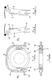
- FIGS. 4 Such a conventional gear shift device is shown in FIGS. 4 shown.
- a fixed sleeve 1 rotatably connected to a shaft 2.
- An axially displaceable shift sleeve 3 is arranged in a rotationally fixed manner on the fixed sleeve 1.
- the shift sleeve 3 has a circumferential on its outer circumference Groove 4 into which a shift fork 5 engages, which has a shift rod 6 connected is. By actuating the shift rod 6, the shift sleeve 3 be axially shifted and a gear shifted.
- a shift rocker is U-shaped and points at its two opposite Legs pivot bearings on, in the gear-fixed bearing journal intervention.
- a similar switching rocker according to the prior art is in the figures 5-8.
- movable sliding blocks 10, 11 are mounted, which in the circumferential groove 4 of the Engage shift sleeve 3.
- the rocker arm 7 is around by a journal 12, 13 formed pivot axis pivotable to the "left” or “right", what is shown in Figures 6, 7.
- a driver 14 is provided for pivoting the switching rocker 7, which is connected to a shift shaft, not shown here.
- the object of the invention is to provide a transmission that has a small number of individual components and that a variety of switching stages allows.
- the invention relates to a manual transmission with at least two side by side arranged "gear stages".
- Each of the two gear stages is formed by two meshing gears.
- Assigned to each other Gears of the two gear stages are each arranged coaxially, that is, they each have a common axis of rotation.
- Between the axially adjacent gears of the two gear stages a shift sleeve is provided which is displaceable along the respective axis of rotation is.
- the gearshift sleeves enable a rotating coupling of the neighboring ones Gear pairs.
- the basic principle of the invention is that the two shift sleeves are "coupled" to each other in the direction of displacement.
- the two Sliding sleeves can therefore only be moved together.
- the two are Shift sleeves can only be moved axially in the same direction. This has to be done but don't be like that.
- Shift sleeves coupled so that they are simultaneously be moved, but in opposite directions, what later is explained in detail.
- each gearshift sleeve has at least two positions, namely a "switch position" and one "Neutral position". In the switch position, they are arranged side by side Gears rotatably coupled via the gearshift sleeve. In contrast, in the neutral position the gears arranged side by side are independent of each other rotatable. According to a development of the invention, it is now provided that that one of the two shift sleeves of the gear stages is in each case their shift position and the other shift sleeve finds the neutral position occupies or vice versa.
- the mechanical coupling can be easily formed by a common actuator his.
- a shift fork or a rocker arm can be provided engage with sliding blocks in grooves on the outer circumference of the two shift sleeves are provided.
- the shift fork that engages in the two shift sleeves can be actuated, for example, by a single shift rod, which in Area between the two shift sleeves is connected to the shift fork and essentially parallel to the two axes of rotation of the gear pairs extends.
- two shift rods can be provided each in the outer area of the gears of a pair of gears with the shift fork are connected.
- a total of three bars are provided, namely a shift rod in the area between the two axes of rotation of the Gear pairs is connected to the shift fork and the actual Actuator for moving the shift fork is provided. Furthermore, in the outer regions of the two gears a pair of gears A guide rod is provided, which the shift fork enforce and prevent the shift fork from tilting when moving. In the "guide holes" of the shift fork can slide or Rolling bearings can be provided, which reduces the switching forces required and thus improves shifting comfort.
- a shift rocker can be provided, which engages in the two shift sleeves via sliding blocks.
- the shift arm is about a transverse to the axes of rotation of the two gear pairs Swivel axis swiveling.
- the rocker arm preferably has the shape a "U” and overlaps the two shift sleeves with their "crossbar”.
- the Both "swivel arms” of the U-shaped rocker arm are fixed with gears Pivot bearings connected.
- sliding blocks are provided, in circumferential grooves on the outer circumference of the two shift sleeves intervention.
- an additional “third arm” is provided, which runs parallel to the two swivel arms and with the Crossbar of the shift arm is connected.
- the third arm extends in the area between the two shift sleeves.
- Can on the third arm also sliding blocks can be provided, which in the circumferential grooves Intervene shift sleeves. These additional sliding blocks improve the Shifting comfort.
- the third arm is preferably also fixed to a gear Pivot bearing connected.
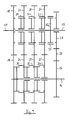
- Figure 9 shows a manual transmission with an input shaft 15, a countershaft 16 and an output shaft 17.
- Two gear sleeves 29, 30 and 31, 32 and 33, 34 which are coupled to one another, are assigned to two pairs of gearwheels lying side by side in the axial direction.
- the "shift sleeve pairs" 29, 30 and 31, 32 and 33, 34 each have two switching positions, namely a "left switching position” and a "right switching position". A distinction must also be made between the switching positions of the two switching sleeves of a pair of switching sleeves.
- Each gearshift sleeve has a gearshift or engagement position in which the gearwheels lying next to one another in the axial direction are rotationally coupled by the gearshift sleeve in question. There is also a neutral position in which adjacent gears can be rotated independently of one another. In FIG. 9 , the shift sleeves 29, 31, 33 are in the neutral position and the shift sleeves 30, 32, 34 are in the shift or engagement position.
- the two shift sleeves of a pair of shift sleeves are each in different shift positions. This means, for example, as shown in FIG. 9 , the shift sleeve 29 is in the neutral position and the shift sleeve 30 coupled to it is in the shift or engagement position.
- both shift sleeves of a pair of shift sleeves are coupled to one another in the axial or displacement direction. This means that both shift sleeves of a pair of shift sleeves are always in Axial direction shifted. If, for example, the pair of shift sleeves 29, 30 is shifted to the left, the shift sleeve 29 comes into the shift or engaged position and the shift sleeve 30 in the neutral position. The same applies to the Shift sleeve pairs 31, 32 and 33, 34. The two shift sleeves one Shift sleeve pairs are always moved in the same direction.
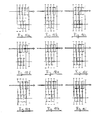
- FIGS. 10a-10i show the nine possible shift positions of the transmission shown in FIG. 9 .
- Figure 10a shows the torque flow when reverse gear is engaged.
- Figures 10b - 10i show the torque flows of the eight possible forward gears. From the positions of the individual shift sleeves it can be seen that the shift sleeves 29, 30 or 31, 32 or 33, 34 can only be moved in pairs to the left or right.
- FIG. 11 shows a logic table for the forward gear stages and the reverse gear stage shown in FIGS . 10a-10i and an additional neutral position, which is shown in FIG. 9 .
- shift sleeves of a shift sleeve pair are respectively shown, for example, the shift sleeve pair 29, 30 (see FIG. 9).
- a shift fork 36 is also shown in each case.
- the shift fork 36 engages in circumferential grooves provided on the outer circumferences of the shift sleeves 29, 30 (cf. FIGS. 1-4).
- a shift rod 37 is provided in the area between the two shift sleeves 29, 30, via which the shift fork 36 is mounted and which enables the shift fork 36 and the shift sleeves 29, 30 engaged therewith to be axially displaced.
- two shift rods 38, 39 are provided, which are each arranged in the “outer area” of the shift sleeves 29, 30.
- the two shift rods 38, 39 run parallel to the axes of rotation of the assigned gear pairs or the shift sleeves 29, 30 and can only be moved together.
- the shift fork 36 is double-supported, which prevents tilting even more reliably.
- a shift rod 37 is provided in the middle, similarly to FIG. 12 , which enables the shift fork 36 to be axially displaced.
- two guide rods 40, 41 are provided in the outer regions of the shift sleeves 29, 30, which pass through associated guide bores 42, 43 of the shift fork 36.
- the guide rods 40, 41 can be slide or roller-mounted in the guide bores 42, 43. This "double" guidance of the shift fork 36 reliably prevents canting.
- FIGS. 15 and 16 show two different variants in which the shift sleeves 29, 30 are axially displaceable by means of an associated shift rocker 44.
- the shift rocker 44 has a "crossbar" 45, two lateral pivot arms 46, 47 and a central pivot arm 48, the ends of which are each pivotably connected to a pivot axis 49 which is mounted on the gearbox.
- the crossbar 45 "overlaps” the shift sleeves 29, 30 and has a shift finger 50 in the middle, via which the shifting force is introduced.
- sliding blocks 51-53 are provided, which engage in circumferential grooves on the outer circumference of the shift sleeves 29, 30.
- FIG. 16 shows a variant of the shift rocker of FIG . 15 .
- the switching rocker 44 is pivotally mounted only on the two lateral pivot arms 46, 47 on pivot pins 54, 55.
- the middle arm 48 serves here only as a holder for the sliding block 52.
- FIG 17 shows an embodiment in which the shift sleeves 29, 30 are displaceable in opposite directions.
- a U-shaped rocker arm 44 is provided, which has two pivot arms 46, 47.
- the rocker arm 44 is pivotally mounted about a pivot axis 49.
- the pivot axis 49 is arranged in a region between the two shift sleeves 29, 30. It lies here in the plane of the drawing and runs perpendicular to the "displacement axes" of the two shift sleeves 29, 30 perpendicular to the drawing plane.
- the shift sleeves 29, 30 are in the direction of displacement via sliding blocks 51, 51a and 52 , 52a coupled to the pivot arms of the shift rocker 44.
- the shifting force is introduced into the shift rocker 44 via a shift finger 50.
- Embodiments consist in that when pivoting the Shift rocker 44 around the pivot axis 49, the two shift sleeves 29, 30 move in different directions. If the shift sleeve 29 from the drawing plane is moved out, the shift sleeve 30 in the Moved the drawing layer in and vice versa.
- Such a rocker arm can of course together with other shift rockers or shift forks where the shift sleeves are moved "in the same direction" (see. Fig. 9-16) integrated into a gear his. This results in a variety of circuit options.
Landscapes
- Engineering & Computer Science (AREA)
- General Engineering & Computer Science (AREA)
- Mechanical Engineering (AREA)
- Gear-Shifting Mechanisms (AREA)
Applications Claiming Priority (2)
| Application Number | Priority Date | Filing Date | Title |
|---|---|---|---|
| DE2002106470 DE10206470A1 (de) | 2002-02-16 | 2002-02-16 | Schaltgetriebe |
| DE10206470 | 2002-02-16 |
Publications (2)
| Publication Number | Publication Date |
|---|---|
| EP1336775A2 true EP1336775A2 (fr) | 2003-08-20 |
| EP1336775A3 EP1336775A3 (fr) | 2005-01-12 |
Family
ID=27618724
Family Applications (1)
| Application Number | Title | Priority Date | Filing Date |
|---|---|---|---|
| EP03000719A Withdrawn EP1336775A3 (fr) | 2002-02-16 | 2003-01-13 | Fourchette double pour boite de vitesse |
Country Status (2)
| Country | Link |
|---|---|
| EP (1) | EP1336775A3 (fr) |
| DE (1) | DE10206470A1 (fr) |
Cited By (1)
| Publication number | Priority date | Publication date | Assignee | Title |
|---|---|---|---|---|
| CN115654126A (zh) * | 2022-09-09 | 2023-01-31 | 重庆齿轮箱有限责任公司 | 一种互锁换挡轧机齿轮箱 |
Families Citing this family (3)
| Publication number | Priority date | Publication date | Assignee | Title |
|---|---|---|---|---|
| DE102012222540B4 (de) * | 2012-12-07 | 2022-02-17 | Schaeffler Technologies AG & Co. KG | Anordnung zum Schalten von zumindest zwei Losrädern an zwei zugeordneten Wellen für ein Getriebe eines Fahrzeugs |
| CN109681540B (zh) * | 2018-11-08 | 2025-12-30 | 吴有智 | 双联模式切换离合器及其变速器应用结构 |
| CN109878320A (zh) * | 2019-03-21 | 2019-06-14 | 力帆实业(集团)股份有限公司 | 一种基于amt的汽车混合动力结构 |
Family Cites Families (8)
| Publication number | Priority date | Publication date | Assignee | Title |
|---|---|---|---|---|
| DE586210C (de) * | 1931-04-04 | 1933-10-19 | Daimler Benz Akt Ges | Schaltvorrichtung fuer Wechselkupplungen, insbesondere fuer Kraftfahrzeuggetriebe |
| US1982976A (en) * | 1932-10-21 | 1934-12-04 | Alltree Arthur | Change speed gearing |
| DE686741C (de) * | 1936-01-31 | 1940-01-15 | Daimler Benz Akt Ges | Mehrgaengiges Zahnraederwechselgetriebe, insbesondere fuer Kraftfahrzeuge |
| IT1161521B (it) * | 1983-10-21 | 1987-03-18 | Iveco Fiat | Dispositivo per la selezione ed il comando delle marce di un cambio di velocita di veicoli in particolare di veicoli industriali |
| DE3822330A1 (de) * | 1988-01-09 | 1989-07-27 | Rudolf Prof Dr Ing Franke | Stirnradwechselgetriebe, insbesondere fuer kraftfahrzeuge |
| DE4131162A1 (de) * | 1991-09-19 | 1993-03-25 | Porsche Ag | Schaltvorrichtung fuer ein geschwindigkeitswechselgetriebe eines kraftfahrzeuges |
| US5309782A (en) * | 1992-09-25 | 1994-05-10 | Borg-Warner Automotive, Inc. | Multiple ratio manual transmission |
| DE10259485A1 (de) * | 2002-12-19 | 2004-07-22 | Bayerische Motoren Werke Ag | Getriebeschaltanordnung mit einer Schaltwalze zum gleichzeitigen Schalten von zwei Schaltmuffen |
-
2002
- 2002-02-16 DE DE2002106470 patent/DE10206470A1/de not_active Withdrawn
-
2003
- 2003-01-13 EP EP03000719A patent/EP1336775A3/fr not_active Withdrawn
Cited By (2)
| Publication number | Priority date | Publication date | Assignee | Title |
|---|---|---|---|---|
| CN115654126A (zh) * | 2022-09-09 | 2023-01-31 | 重庆齿轮箱有限责任公司 | 一种互锁换挡轧机齿轮箱 |
| CN115654126B (zh) * | 2022-09-09 | 2025-09-05 | 重庆齿轮箱有限责任公司 | 一种互锁换挡轧机齿轮箱 |
Also Published As
| Publication number | Publication date |
|---|---|
| EP1336775A3 (fr) | 2005-01-12 |
| DE10206470A1 (de) | 2003-08-28 |
Similar Documents
| Publication | Publication Date | Title |
|---|---|---|
| DE102009017537B3 (de) | Doppelkupplungsgetriebe mit drei Triebwellen | |
| EP0532924B1 (fr) | Dispositif de changement de vitesses pour une boîte de vitesses d'une véhicule automobile | |
| EP0731885B1 (fr) | Dispositif de changement de vitesse | |
| DE19843584B4 (de) | Schalteinrichtung eines mehrstufigen Schaltgetriebes | |
| EP0557707A1 (fr) | Procédé de commander une boîte de vitesse pour une voiture | |
| DE10316163A1 (de) | Mehrstufiges Schaltgetriebe für eine Brennkraftmaschine | |
| DE922508C (de) | Schaltvorrichtung fuer Kraftfahrzeug-Wechselgetriebe | |
| DE112006002161T5 (de) | Doppelvorgelege-Getriebe | |
| DE3526150C2 (fr) | ||
| DE202009005634U1 (de) | Doppelkupplungsgetriebe | |
| DE2341199A1 (de) | Schalteinrichtung fuer mechanische wechselgetriebe von kraftfahrzeugen | |
| WO1990015272A1 (fr) | Dispositif de changement de vitesses pour la boite de vitesses de vehicules a moteur | |
| DE10151467A1 (de) | Schaltgetriebe mit Verriegelungseinrichtung zur Verriegelung einzelner Gänge | |
| DE19840621A1 (de) | Vorrichtung und Verfahren zum servomechanischen Schalten eines Stufengetriebes | |
| DE4017957A1 (de) | Schalteinrichtung eines kraftfahrzeuggetriebe | |
| EP1336775A2 (fr) | Fourchette double pour boite de vitesse | |
| EP2655925B1 (fr) | Procédé pour la modification d'une boîte de vitesses manuelle | |
| DE10142225A1 (de) | Einstangen-Schalteinrichtung für Kraftfahrzeug-Handschaltgetriebe | |
| WO2005078320A1 (fr) | Dispositif de commutation a une seule tringle sur une boite de vitesses | |
| DE3840403A1 (de) | Mechanisches schaltgetriebe fuer nutzfahrzeuge | |
| EP1302706B1 (fr) | Boíte de vitesses | |
| DE102010052746B4 (de) | Kompaktes Schaltgetriebe | |
| DE102020005168B3 (de) | Doppelkupplungsgetriebe | |
| DE102018206392A1 (de) | Schalteinrichtung zur durchführung von gangwechseln in einem fahrzeuggetriebe | |
| DE613703C (de) | Geschwindigkeitswechselgetriebe zum Antrieb der Arbeitsspindeln von Werkzeugmaschinen, vorzugsweise Drehbaenken |
Legal Events
| Date | Code | Title | Description |
|---|---|---|---|
| PUAI | Public reference made under article 153(3) epc to a published international application that has entered the european phase |
Free format text: ORIGINAL CODE: 0009012 |
|
| AK | Designated contracting states |
Designated state(s): AT BE BG CH CY CZ DE DK EE ES FI FR GB GR HU IE IT LI LU MC NL PT SE SI SK TR |
|
| AX | Request for extension of the european patent |
Extension state: AL LT LV MK RO |
|
| PUAL | Search report despatched |
Free format text: ORIGINAL CODE: 0009013 |
|
| AK | Designated contracting states |
Kind code of ref document: A3 Designated state(s): AT BE BG CH CY CZ DE DK EE ES FI FR GB GR HU IE IT LI LU MC NL PT SE SI SK TR |
|
| AX | Request for extension of the european patent |
Extension state: AL LT LV MK RO |
|
| 17P | Request for examination filed |
Effective date: 20041208 |
|
| AKX | Designation fees paid |
Designated state(s): DE FR GB IT |
|
| STAA | Information on the status of an ep patent application or granted ep patent |
Free format text: STATUS: THE APPLICATION HAS BEEN WITHDRAWN |
|
| 18W | Application withdrawn |
Effective date: 20060222 |