EP1336793A1 - Offenes Zahnradgetriebe und Schmierstoff-Sammler - Google Patents
Offenes Zahnradgetriebe und Schmierstoff-Sammler Download PDFInfo
- Publication number
- EP1336793A1 EP1336793A1 EP02026954A EP02026954A EP1336793A1 EP 1336793 A1 EP1336793 A1 EP 1336793A1 EP 02026954 A EP02026954 A EP 02026954A EP 02026954 A EP02026954 A EP 02026954A EP 1336793 A1 EP1336793 A1 EP 1336793A1
- Authority
- EP
- European Patent Office
- Prior art keywords
- lubricant
- gear transmission
- transmission according
- gear
- take
- Prior art date
- Legal status (The legal status is an assumption and is not a legal conclusion. Google has not performed a legal analysis and makes no representation as to the accuracy of the status listed.)
- Granted
Links
- 239000004519 grease Substances 0.000 title description 4
- 239000000314 lubricant Substances 0.000 claims abstract description 96
- 230000005540 biological transmission Effects 0.000 claims description 31
- 230000033001 locomotion Effects 0.000 claims description 7
- 230000002745 absorbent Effects 0.000 claims description 3
- 239000002250 absorbent Substances 0.000 claims description 3
- 230000007613 environmental effect Effects 0.000 description 4
- 230000005484 gravity Effects 0.000 description 2
- 230000000007 visual effect Effects 0.000 description 2
- 238000004140 cleaning Methods 0.000 description 1
- 238000011109 contamination Methods 0.000 description 1
- 230000003247 decreasing effect Effects 0.000 description 1
- 239000006260 foam Substances 0.000 description 1
- 230000003287 optical effect Effects 0.000 description 1
- 239000002689 soil Substances 0.000 description 1
- 239000000126 substance Substances 0.000 description 1
- XLYOFNOQVPJJNP-UHFFFAOYSA-N water Substances O XLYOFNOQVPJJNP-UHFFFAOYSA-N 0.000 description 1
Images
Classifications
-
- F—MECHANICAL ENGINEERING; LIGHTING; HEATING; WEAPONS; BLASTING
- F16—ENGINEERING ELEMENTS AND UNITS; GENERAL MEASURES FOR PRODUCING AND MAINTAINING EFFECTIVE FUNCTIONING OF MACHINES OR INSTALLATIONS; THERMAL INSULATION IN GENERAL
- F16N—LUBRICATING
- F16N31/00—Means for collecting, retaining, or draining-off lubricant in or on machines or apparatus
- F16N31/02—Oil catchers; Oil wipers
-
- F—MECHANICAL ENGINEERING; LIGHTING; HEATING; WEAPONS; BLASTING
- F16—ENGINEERING ELEMENTS AND UNITS; GENERAL MEASURES FOR PRODUCING AND MAINTAINING EFFECTIVE FUNCTIONING OF MACHINES OR INSTALLATIONS; THERMAL INSULATION IN GENERAL
- F16H—GEARING
- F16H57/00—General details of gearing
- F16H57/04—Features relating to lubrication or cooling or heating
- F16H57/0406—Absorption elements for lubricants, e.g. oil felts
-
- F—MECHANICAL ENGINEERING; LIGHTING; HEATING; WEAPONS; BLASTING
- F16—ENGINEERING ELEMENTS AND UNITS; GENERAL MEASURES FOR PRODUCING AND MAINTAINING EFFECTIVE FUNCTIONING OF MACHINES OR INSTALLATIONS; THERMAL INSULATION IN GENERAL
- F16H—GEARING
- F16H57/00—General details of gearing
- F16H57/04—Features relating to lubrication or cooling or heating
- F16H57/0408—Exchange, draining or filling of transmission lubricant
-
- F—MECHANICAL ENGINEERING; LIGHTING; HEATING; WEAPONS; BLASTING
- F16—ENGINEERING ELEMENTS AND UNITS; GENERAL MEASURES FOR PRODUCING AND MAINTAINING EFFECTIVE FUNCTIONING OF MACHINES OR INSTALLATIONS; THERMAL INSULATION IN GENERAL
- F16H—GEARING
- F16H57/00—General details of gearing
- F16H57/04—Features relating to lubrication or cooling or heating
- F16H57/0463—Grease lubrication; Drop-feed lubrication
-
- F—MECHANICAL ENGINEERING; LIGHTING; HEATING; WEAPONS; BLASTING
- F16—ENGINEERING ELEMENTS AND UNITS; GENERAL MEASURES FOR PRODUCING AND MAINTAINING EFFECTIVE FUNCTIONING OF MACHINES OR INSTALLATIONS; THERMAL INSULATION IN GENERAL
- F16H—GEARING
- F16H57/00—General details of gearing
- F16H57/04—Features relating to lubrication or cooling or heating
- F16H57/048—Type of gearings to be lubricated, cooled or heated
- F16H57/0493—Gearings with spur or bevel gears
Definitions
- the invention relates to an open gear transmission according to the preamble of the claim 1 and a lubricant collector according to the preamble of claim 19.
- Open gear transmissions have the disadvantage that at least part of a rotationally driven Gear is exposed and lubricant (grease, oil or other Lubricants) from the tooth flanks by the gear engagement gradually mainly migrate towards the side surfaces of the gear, there exits and either fall down or collect on the sides and then fall down. Lubricants are for the most part environmentally harmful. In wind turbines, Ski lifts, conveyors, and similar facilities with open gears So the lubricant gets into the environment, into the water or into the soil where it is critical Can cause contamination.
- lubricant grey, oil or other Lubricants
- the invention is based on the object, an open gear transmission of the above and a lubricant collector with which the environmental hazard by uncontrolled exiting from open gear transmissions lubricant is prevented.
- the lubricant removal element permanently removes the lubricant from the gear and promotes him to the discharge device, where he removed from the acceptance element and brought into the collection chamber. In the collection chamber is the lubricant safely salvaged. The collection chamber is then emptied regularly. The collected If necessary, lubricant can be recycled or disposed of, and no longer gets into the environment.
- the lubricant collector is a simple, universal usable unit with which the environmental hazard of open gear transmission eliminate it.
- the drive on a pinion, which is driven by the gear transmission is, and preferably even with the one contacted by the pick-up or a meshes other gear of the gear transmission to the conveying movement on the Transfer acceptance element.
- the acceptance element is disc-shaped or round brush-shaped and rotatably disposed, wherein its contact area with the gear be compliant should.
- the decrease element may also consist of several, about a drive axle rotatably arranged single brush or Einzelabstreifern exist during the conveying movement successively act on the gear.
- the acceptance element should absorbent and yielding deformable at least in its outer area be educated.
- the discharge device can at least one stationary relative to the decrease element, have on this attacking scraper, that of the decrease element brought lubricant takes over for the most part. If the Collecting chamber is arranged below the discharge device, the gravity used to convey the absorbed lubricant into the collection chamber.
- the Deriving device could also include several scrapers. Basically you can also centrifugal forces are used to convey the lubricant, e.g. if the whole Gearbox rotates.
- the gear is a spur gear substantially flat side surfaces.
- the grease collector is arranged so that the decrease element the side face of the in any direction downward facing Gear from the outside and contacted on the underside and thereby over the tooth gap reasons engages inside. In this way it is ensured that the whole Area of the side surface of the gear is cleaned of lubricant on which To collect lubricant.
- the overhead side surface is in terms of Environmental hazard less critical, since there is collecting lubricant anyway gradually comes down and then also carried away from the pickup element becomes.
- the drive should expediently attack a shaft at which the or Decreasing elements are arranged.
- the rotary motion transmitting pinion should be arranged on the shaft be and have a smaller outer diameter than the decrease element.
- the pinion is expediently in between arranged on the shaft.
- the discharge device is expediently remote from the gearwheel Page inside the lubricant collector arranged to ensure that The removed lubricant is not accidentally removed from the lubricant collector can step outside.
- the lubricant collector is formed with a tubular housing, that can be comfortably set in any position in association with the gear, the housing comprises an upper receiving section and a lower collecting section, are the take-off element, the drive and the discharge device in the upper receiving section arranged, the collecting chamber is located in the lower collecting section, in order to be able to use the force of gravity, and at least leads from the upper section a discharge path into the collection chamber. In this way, comes from the gear removed lubricant conveniently in the collection chamber.
- the lubricant collector may otherwise be equipped with a level indicator device, which then a offers visual or visual signal when the collection chamber becomes full threatening.
- each pick-up element could simultaneously clean more than one gear, or could in a collector several decrease elements for several gears be provided.
- the at least one decrease element should predominantly inside the be stored in the upper receiving section and through a wall slot to the outside to Project gear. As a result, the removed lubricant reaches the shortest Way inside the lubricant collector and are the moving and stationary Components of the lubricant collector housed protected against environmental influences.
- the lower collecting section of the housing a removable Container. This facilitates the quick and easy removal of the collected Lubricant without disassembly of the lubricant collector.
- the discharge device is a standing wall mounted with the Stripping and crushing edges on the acceptance element attacks and brought Lubricant positively and positively removed, so that the decrease element at renewed contact with the gear again fully receptive.
- the wall can be a flat or curved plate into which from the edges to a Middle bar extending slots are formed, which are towards the central pier converge.
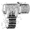
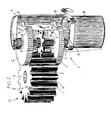
- Figs. 1 and 2 show a lubricated spur gear Z of an open gear transmission G and the gear Z operatively associated lubricant collector F.
- the lubricant collector F which is a stand-alone unit, becomes described below in connection with the gear Z.
- the spur gear Z has teeth and tooth gaps 1, 2, on side surfaces 3, 4 end up. Since the spur gear Z is lubricated (with grease, oil or another Lubricant) gradually moves lubricant S to the side surfaces 3, 4, where it is deposits.
- the operatively associated with the spur gear Z lubricant collector F has in the embodiment shown, two disc-shaped lubricant decrease elements C, which are arranged approximately parallel to the side surfaces 3, 4 and are spaced approximately with the gear width.
- Each acceptance element C is for example a round brush, a felt disc or a foam disc or Like., That is, a structure, the absorbent and elastically deformable at least in the outer region is.
- the decrease element C could also be made of a variety consist of individual scrapers or brushes, the finger-like strive to the outside.
- the lubricant collector F has an approximately tubular, closed at both ends Housing A, which consists of an upper decrease section O and a lower collection section U exists.
- the collecting section U can be designed as a removable container B. be.
- Above the collecting section U is at least one fastener 5, e.g. a flange provided with which the lubricant collector F in its operating position is mounted in association with the spur gear Z.
- the two decrease elements C are in the interior of the upper decrease section O order a common axis X rotatably mounted and engage through wall slots 6 Outside. They stand with the side surfaces 3, 4 in permanent stripping contact and engage from outside to beyond the tooth gap 2 reasons on the side surfaces 3, 4th
- a storage 7 On top of a lid of the upper receiving section O a storage 7 is indicated. Further, a drive D in the lubricant collector F is included, with each Pickup element C can be driven to a rotating conveying movement. Im shown Embodiment, the drive D, a pinion R, which with the spur gear Z meshes, the rotational movement picks up, and the decrease elements C in opposite directions to the spur gear Z drives.
- a separate drive D for or the decrease elements C may be provided, e.g. a separate electric motor or the like.
- the lubricant collector F in FIGS. 1 and 2 is provided with two removal elements C shown, the two side surfaces 3, 4 of the spur gear Z act stripping. However, it would be sufficient, if necessary, only in Figs. 1 and 2 below provided decrease element C and to clean only the lower side surface 4.
- both decrease elements C are rotationally fixed on a common shaft 8 or arranged largely rotationally fixed, which is mounted in the bearings 7.
- the pinion R sits between the two decrease elements C on the shaft 8 and meshes with the teeth 1 of the spur gear Z.
- a collection chamber K defines.
- a lubricant guide path 9 leads from the upper Recording section O.
- Each acceptance element C is a lubricant discharge device V operatively assigned.
- this consists of a wall 10, e.g. a flat or curved plate standing, i. approximately parallel to the axis the shaft 8 is mounted in the upper receiving section O (e.g., welded), and is within the outer diameter of the decrease elements C.
- the outer peripheries of the decrease elements C are each to a Middle web 13 converging slots with Abstreif- and crushing edges 12 in the Molded plate.
- a slot 11 for reaching through the pinion R provided.
- the lubricant collector F is mounted so that the two decrease elements C the side surfaces 3, 4 of the spur gear Z contact with predetermined contact pressure. As soon as the spur gear Z rotates, the two decrease elements also rotate C, and becomes any lubricant collecting on the side surfaces 3, 4 S stripped from the decrease elements C and the discharge device V in the interior promoted the fatty substance collector F.
- the diverter V takes the brought Lubricant for the most part from each decrease element C from. This lubricant then runs along the guide path 9 down into the collection chamber K. As soon as the collection chamber K is full, it is removed and emptied.
- a level indicator is provided, which is an optical or acoustic Signal offers as soon as the collection chamber K threatens to become full.
- the lubricant collector F works independently of the direction of rotation of the spur gear Z.
- the decrease elements or the decrease element designed and arranged to accumulate lubricant lose weight where it deposits with this other gear type. Should that be too cleaning gear take an oblique position in space, then the housing could A be designed so that the lower collecting section U opposite the upper Shooting section O kinks and is positioned substantially vertically.
- the components, which consists of the lubricant collector F, can predominantly Be formed plastic that is resistant to the respective lubricant type. This results in a low weight of the lubricant collector.
- the pinion R can in its diameter together with the diameters of the decrease elements so be matched to the diameter of the gear or its number of teeth that a translation into the faster or the slower results.
- the lubricant collector F this could be designed so that optionally the one or more decrease elements in the same direction with the gear rotate, and possibly much slower or faster than this.
Landscapes
- Engineering & Computer Science (AREA)
- General Engineering & Computer Science (AREA)
- Mechanical Engineering (AREA)
- General Details Of Gearings (AREA)
Abstract
Description
- Fig. 1
- eine schematische Seitenansicht eines Teils eines offenen Zahnradgetriebes mit einem zugeordneten Schmierstoff-Sammler, und
- Fig. 2
- eine Ansicht ähnlich der von Fig. 1, wobei Teile des SchmierstoffSammlers weggebrochen sind.
Claims (19)
- Offenes Zahnradgetriebe (G), mit wenigstens einem drehangetriebenen, geschmierten Zahnrad (Z), das zumindest zum Teil freiliegend angeordnet ist, dadurch gekennzeichnet, dass dem Zahnrad (Z) ein Schmierstoffsammler (F) zugeordnet ist, der wenigstens ein das Zahnrad (Z) kontaktierendes Schmierstoff-Abnahmeelement (C), eine das Schmierstoff-Abnahmeelement (C) beaufschlagende Schmierstoff-Ableitvorrichtung (V), wenigstens eine Sammelkammer (K), und einen Antrieb (D) aufweist, mit dem das Schmierstoff-Abnahmeelement (C) zu einer vom Zahnrad (Z) zur Schmierstoff-Ableitvorrichtung (V) gerichteten Förderbewegung antreibbar ist.
- Offenes Zahnradgetriebe nach Anspruch 1, dadurch gekennzeichnet, dass der Antrieb (D) ein mit dem Schmierstoff-Abnahmeelement (C) gekoppeltes Ritzel (R) aufweist, das von dem Zahnradgetriebe (G) angetrieben wird, vorzugsweise mit dem vom Schmierstoff-Abnahmeelement (C) kontaktierten oder einem anderen Zahnrad des Zahnradgetriebes kämmt.
- Offenes Zahnradgetriebe nach Anspruch 1, dadurch gekennzeichnet, dass der Schmierstoff-Sammler (F) einen eigenen Antrieb für das Schmierstoff-Abnahmeelement (C) aufweist.
- Offenes Zahnradgetriebe nach Anspruch 1, dadurch gekennzeichnet, dass das Schmierstoff-Abnahmeelement (C) scheibenförmig oder rundbürstenförmig ausgebildet und drehbar angeordnet ist, und einen nachgiebigen Kontaktbereich aufweist.
- Offenes Zahnradgetriebe nach Anspruch 1, dadurch gekennzeichnet, dass das Schmierstoff-Abnahmeelement (C) mehrere um eine Antriebsachse (X) drehbar angeordnete Einzelbürsten oder Einzelabstreifer aufweist.
- Offenes Zahnradgetriebe nach Anspruch 1, dadurch gekennzeichnet, dass das Schmierstoff-Abnahmeelement (C) saugfähig, und vorzugsweise im Außenbereich nachgiebig verformbar, ausgebildet ist.
- Offenes Zahnradgetriebe nach Anspruch 1, dadurch gekennzeichnet, dass die Schmierstoffableitvorrichtung (V) wenigstens einen relativ zum Schmierstoff-Abnahmeelement (C) angreifenden Abstreifer aufweist, und dass die Sammelkammer (K) unterhalb der Schmierstoff-Ableitvorrichtung (V) angeordnet ist.
- Offenes Zahnradgetriebe nach wenigstens einem der vorhergehenden Ansprüche, dadurch gekennzeichnet, dass das Zahnrad (Z) ein Stirnrad mit im Wesentlichen ebenen Seitenflächen (3, 4) ist, und dass der Schmierstoff-Sammler (F) so angeordnet ist, dass das Schmierstoff-Abnahmeelement (C) die nach unten weisende Seitenfläche (4) von außen her unten kontaktiert und bis über die Zahnlückengründe (2) nach innen greift.
- Offenes Zahnradgetriebe nach wenigstens einem der Ansprüche 1 bis 7, dadurch gekennzeichnet, dass das Zahnrad (Z) ein Stirnrad mit im Wesentlichen ebenen Seitenflächen (3, 4) ist, dass der Schmierstoff-Sammler (F) zwei mit der Zahnradbreite beabstandete Schmierstoff-Abnahmeelemente (C) aufweist, und dass der Schmierstoff-Sammler (F) so angeordnet ist, dass jedes Schmierstoff-Abnahmeelement eine Seitenfläche (3, 4) von außen her kontaktiert und bis über die Zahnlückengründe (2) nach innen greift.
- Offenes Zahnradgetriebe nach wenigstens einem der vorhergehenden Ansprüche, dadurch gekennzeichnet, dass das eine oder beide Schmierstoff-Abnahmeelement (C) auf einer Welle (8) angeordnet sind, mit der der Antrieb (D) verbunden ist.
- Offenes Zahnradgetriebe nach Anspruch 2, dadurch gekennzeichnet, dass das Ritzel (R) auf der Welle (8) sitzt und einen kleineren Außendurchmesser hat als das oder die Schmierstoff-Abnahmeelemente (C).
- Offenes Zahnradgetriebe nach wenigstens einem der vorhergehenden Ansprüche, dadurch gekennzeichnet, dass das Ritzel (R) zwischen den beiden Schmierstoff-Abnahmeelementen (C) auf der Welle (8) angeordnet ist.
- Offenes Zahnradgetriebe nach Anspruch 1, dadurch gekennzeichnet, dass die Schmierstoff-Ableitvorrichtung (V) auf der dem Zahnrad (Z) abgewandten Seite im Schmierstoff-Sammler (F) angeordnet ist.
- Offenes Zahnradgetriebe nach wenigstens einem der vorhergehenden Ansprüche, dadurch gekennzeichnet, dass der Schmierstoffsammler (F) ein rohrartiges Gehäuse (A) mit wenigstens einem Befestigungselement (5) aufweist, dass das Gehäuse (A) eine obere Aufnahmesektion (O) und eine untere Sammelsektion (U) aufweist, dass das wenigstens eine Schmierstoff-Abnahmeelement (C), der Antrieb (D) und die Ableitvorrichtung (V) in der oberen Aufnahmesektion (O) angeordnet sind, dass die Sammelkammer (K) in der unteren Sammelsektion (U) vorgesehen ist, und dass von der oberen Aufnahmesektion (O) wenigstens ein Schmierstoff-Ableitpfad (9) nach unten in die Sammelkammer (K) führt.
- Offenes Zahnradgetriebe nach wenigstens einem der vorhergehenden Ansprüche, dadurch gekennzeichnet, dass das wenigstens eine Schmierstoff-Abnahmeelement (C) mit der Welle (8) im Inneren der oberen Aufnahmesektion (O) gelagert ist, und dass das Schmierstoff-Abnahmeelement (C) durch einen Wandschlitz (6) aus der oberen Aufnahmesektion (O) nach außen zum Zahnrad (Z) vorsteht.
- Offenes Zahnradgetriebe nach Anspruch 14, dadurch gekennzeichnet, dass die untere Sammelsektion (U) ein abnehmbarer Behälter (B) ist.
- Offenes Zahnradgetriebe nach Anspruch 1, dadurch gekennzeichnet, dass die Schmierstoff-Ableitvorrichtung (V) eine, vorzugsweise parallel zur Drehachse des Schmierstoff-Abnahmeelements (C), innerhalb des Außendurchmessers des Schmierstoff-Abnahmeelements (C) stehend montierte Wand (10) mit eingeformten, am Schmierstoff-Abnahmeelement (C) angreifenden Abstreif- und Quetschrändern (12) aufweist.
- Offenes Zahnradgetriebe nach Anspruch 17, dadurch gekennzeichnet, dass die Wand (10) eine ebene oder gebogene Platte mit zwei von gegenüberliegenden Plattenrändern ausgehenden, bis zu einem Mittelsteg (13) verlaufenden Schlitzen ist, deren jeder in Richtung zum Mittelsteg (13) konvergierend ausgebildet ist.
- Schmierstoff-Sammler (F) für ein offenes Zahnradgetriebe (G), von dem wenigstens ein geschmiertes Zahnrad zumindest zum Teil freiliegend angeordnet ist, dadurch gekennzeichnet, dass der Schmierstoff-Sammler (F) wenigstens ein zu einer Förderbewegung antreibbares Schmierstoff-Aufnahmeelement (C), eine Schmierstoff-Ableitvorrichtung (V) und wenigstens eine Sammelkammer (K) für vom Schmierstoff-Aufnahmeelement (C) zur Schmierstoff-Ableitvorrichtung (V) geförderten und dort abgenommenen Schmierstoff (S) aufweist.
Applications Claiming Priority (2)
| Application Number | Priority Date | Filing Date | Title |
|---|---|---|---|
| DE20202245U | 2002-02-14 | ||
| DE20202245U DE20202245U1 (de) | 2002-02-14 | 2002-02-14 | Offenes Zahnradgetriebe und Schmierstoff-Sammler |
Publications (2)
| Publication Number | Publication Date |
|---|---|
| EP1336793A1 true EP1336793A1 (de) | 2003-08-20 |
| EP1336793B1 EP1336793B1 (de) | 2008-02-13 |
Family
ID=7967753
Family Applications (1)
| Application Number | Title | Priority Date | Filing Date |
|---|---|---|---|
| EP02026954A Expired - Lifetime EP1336793B1 (de) | 2002-02-14 | 2002-12-04 | Offenes Zahnradgetriebe und Schmierstoff-Sammler |
Country Status (4)
| Country | Link |
|---|---|
| EP (1) | EP1336793B1 (de) |
| DE (2) | DE20202245U1 (de) |
| DK (1) | DK1336793T3 (de) |
| ES (1) | ES2299548T3 (de) |
Families Citing this family (1)
| Publication number | Priority date | Publication date | Assignee | Title |
|---|---|---|---|---|
| DE212010000209U1 (de) | 2010-03-19 | 2012-12-13 | Baier & Köppel GmbH & Co. | Schmierstoffabnahmeeinheit sowie Abnahmeeinrichtung für ein zu schmierendes oder mit Schmierstoff versehenes Zahnrad |
Citations (4)
| Publication number | Priority date | Publication date | Assignee | Title |
|---|---|---|---|---|
| US1699920A (en) * | 1927-09-01 | 1929-01-22 | Joseph Reid Gas Engine Company | Grease-recovering device |
| US3854553A (en) * | 1973-11-01 | 1974-12-17 | Caterpillar Tractor Co | Lubrication system for swing gear drive |
| US3990539A (en) * | 1970-08-05 | 1976-11-09 | Caterpillar Tractor Co. | Lubrication means for swing gear drive |
| US4057126A (en) * | 1976-03-25 | 1977-11-08 | The Falk Corporation | Lubricant wiper |
Family Cites Families (2)
| Publication number | Priority date | Publication date | Assignee | Title |
|---|---|---|---|---|
| JPS5874831A (ja) * | 1981-10-28 | 1983-05-06 | Honda Motor Co Ltd | 過給機付内燃エンジン |
| JPH03107516A (ja) * | 1989-09-20 | 1991-05-07 | Nissan Motor Co Ltd | オイルポンプ |
-
2002
- 2002-02-14 DE DE20202245U patent/DE20202245U1/de not_active Expired - Lifetime
- 2002-12-04 DK DK02026954T patent/DK1336793T3/da active
- 2002-12-04 EP EP02026954A patent/EP1336793B1/de not_active Expired - Lifetime
- 2002-12-04 DE DE50211668T patent/DE50211668D1/de not_active Expired - Lifetime
- 2002-12-04 ES ES02026954T patent/ES2299548T3/es not_active Expired - Lifetime
Patent Citations (4)
| Publication number | Priority date | Publication date | Assignee | Title |
|---|---|---|---|---|
| US1699920A (en) * | 1927-09-01 | 1929-01-22 | Joseph Reid Gas Engine Company | Grease-recovering device |
| US3990539A (en) * | 1970-08-05 | 1976-11-09 | Caterpillar Tractor Co. | Lubrication means for swing gear drive |
| US3854553A (en) * | 1973-11-01 | 1974-12-17 | Caterpillar Tractor Co | Lubrication system for swing gear drive |
| US4057126A (en) * | 1976-03-25 | 1977-11-08 | The Falk Corporation | Lubricant wiper |
Also Published As
| Publication number | Publication date |
|---|---|
| ES2299548T3 (es) | 2008-06-01 |
| DK1336793T3 (da) | 2008-06-02 |
| DE20202245U1 (de) | 2003-06-18 |
| DE50211668D1 (de) | 2008-03-27 |
| EP1336793B1 (de) | 2008-02-13 |
Similar Documents
| Publication | Publication Date | Title |
|---|---|---|
| DE60122291T2 (de) | Förderersystem zum Entfernern von Spänen | |
| DE3322361C2 (de) | ||
| DE10161646A1 (de) | Katzentoilette | |
| DE2604382A1 (de) | Vorrichtung zum reinigen von foerderbaendern | |
| EP2038488A1 (de) | Siebrechen an einer überlaufschwelle einer regenentlastungsanlage | |
| DE2709714A1 (de) | Abstreifvorrichtung fuer reversierbare gurtbaender | |
| DE102004044399A1 (de) | Schmiermittelsäuberungsvorrichtung fürs Trockendrahtziehen | |
| DE1684272B1 (de) | Selbsttaetig arbeitende Reinigungsvorrichtung fuer Gebaeudefassaden und Aussenflaechen von feststehenden Fenstern | |
| DE102004062316A1 (de) | Vorrichtung zum Abscheiden und Abtransport von Abscheidegut | |
| EP1336793B1 (de) | Offenes Zahnradgetriebe und Schmierstoff-Sammler | |
| CH637343A5 (de) | Vorrichtung zum sterilisieren einer bahn aus verpackungsmaterial. | |
| DE69911890T2 (de) | Säuberungsvorrichtung zur ölbeseitigung | |
| DE69115499T2 (de) | Federnde borsten-kassette für den rotor z.b. einer fegmaschine | |
| DE10146180B4 (de) | Vorrichtung zur mechanischen Reinigung eines Förderbandes | |
| DE2949679C2 (de) | Vorrichtung zur Beseitigung von ölartigen Verunreinigungen auf einer Wasseroberfläche | |
| DE1264398B (de) | Verfahren und Vorrichtung zum Auslaugen von zerkleinertem Material | |
| DE4113593C2 (de) | Ölskimmer mit gliederförmigem Förderelement | |
| DE2035548C3 (de) | Vorrichtung zum Reinigen von Förderbändern | |
| EP0108717A2 (de) | Vorrichtung zur Reinigung von Abwasser | |
| DE19853519B4 (de) | Vorrichtung zum Abstreifen von Transportgut | |
| DE4205810C1 (en) | Appts. for floating sludge removal from cleaning basin - has brush bar moved by crank rods over surface towards catch trough back above surface | |
| DE10240459A1 (de) | Abscheidevorrichtung zum Entfernen von aufschwemmenden Ölen | |
| DE2113271A1 (de) | Vorrichtung zur Aufnahme von Verunreinigungen | |
| DE379873C (de) | Vorrichtung zur Ausscheidung schwebender fester Teilchen aus Fluessigkeiten, z. B. Kloakenabwaessern | |
| DE2830843C2 (de) | Elektrostatischer Staubabscheider |
Legal Events
| Date | Code | Title | Description |
|---|---|---|---|
| PUAI | Public reference made under article 153(3) epc to a published international application that has entered the european phase |
Free format text: ORIGINAL CODE: 0009012 |
|
| AK | Designated contracting states |
Designated state(s): AT BE BG CH CY CZ DE DK EE ES FI FR GB GR IE IT LI LU MC NL PT SE SI SK TR |
|
| AX | Request for extension of the european patent |
Extension state: AL LT LV MK RO |
|
| 17P | Request for examination filed |
Effective date: 20040218 |
|
| AKX | Designation fees paid |
Designated state(s): DE DK ES IT |
|
| RAP1 | Party data changed (applicant data changed or rights of an application transferred) |
Owner name: WILLY VOGEL AKTIENGESELLSCHAFT |
|
| 17Q | First examination report despatched |
Effective date: 20070111 |
|
| GRAP | Despatch of communication of intention to grant a patent |
Free format text: ORIGINAL CODE: EPIDOSNIGR1 |
|
| GRAS | Grant fee paid |
Free format text: ORIGINAL CODE: EPIDOSNIGR3 |
|
| GRAA | (expected) grant |
Free format text: ORIGINAL CODE: 0009210 |
|
| AK | Designated contracting states |
Kind code of ref document: B1 Designated state(s): DE DK ES IT |
|
| REF | Corresponds to: |
Ref document number: 50211668 Country of ref document: DE Date of ref document: 20080327 Kind code of ref document: P |
|
| REG | Reference to a national code |
Ref country code: ES Ref legal event code: FG2A Ref document number: 2299548 Country of ref document: ES Kind code of ref document: T3 |
|
| REG | Reference to a national code |
Ref country code: DK Ref legal event code: T3 |
|
| PLBE | No opposition filed within time limit |
Free format text: ORIGINAL CODE: 0009261 |
|
| STAA | Information on the status of an ep patent application or granted ep patent |
Free format text: STATUS: NO OPPOSITION FILED WITHIN TIME LIMIT |
|
| 26N | No opposition filed |
Effective date: 20081114 |
|
| PGFP | Annual fee paid to national office [announced via postgrant information from national office to epo] |
Ref country code: DK Payment date: 20151228 Year of fee payment: 14 |
|
| PGFP | Annual fee paid to national office [announced via postgrant information from national office to epo] |
Ref country code: IT Payment date: 20151221 Year of fee payment: 14 Ref country code: ES Payment date: 20160121 Year of fee payment: 14 |
|
| REG | Reference to a national code |
Ref country code: DK Ref legal event code: EBP Effective date: 20161231 |
|
| PG25 | Lapsed in a contracting state [announced via postgrant information from national office to epo] |
Ref country code: IT Free format text: LAPSE BECAUSE OF NON-PAYMENT OF DUE FEES Effective date: 20161204 |
|
| PG25 | Lapsed in a contracting state [announced via postgrant information from national office to epo] |
Ref country code: DK Free format text: LAPSE BECAUSE OF NON-PAYMENT OF DUE FEES Effective date: 20161231 |
|
| PGFP | Annual fee paid to national office [announced via postgrant information from national office to epo] |
Ref country code: DE Payment date: 20180228 Year of fee payment: 16 |
|
| PG25 | Lapsed in a contracting state [announced via postgrant information from national office to epo] |
Ref country code: ES Free format text: LAPSE BECAUSE OF NON-PAYMENT OF DUE FEES Effective date: 20161205 |
|
| REG | Reference to a national code |
Ref country code: ES Ref legal event code: FD2A Effective date: 20181116 |
|
| REG | Reference to a national code |
Ref country code: DE Ref legal event code: R119 Ref document number: 50211668 Country of ref document: DE |
|
| PG25 | Lapsed in a contracting state [announced via postgrant information from national office to epo] |
Ref country code: DE Free format text: LAPSE BECAUSE OF NON-PAYMENT OF DUE FEES Effective date: 20190702 |